Assignment 2
Creating 1D, 2D and 3D mesh of the component and finally showing the travel of shock wave though the rail by calculating the speed of sound in corresponding rail.
Introduction:
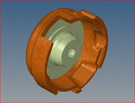
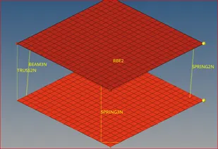
This small project deal with meshing 1D, 2D and 3D elements. In 3D meshing we will be seeing how the 3D Hexa meshing is done and different available option that Hypermesh provide. For 1D mesh, we will only cover SPRING2N, RBE2, TRUSS AND BEAM because these elements are most widely used in CRASHWORHTINESS simulations.
Then after we will perform simple simulation of rail crush under force. In order to determine how the stress wave is flowing through the rail. We will calculate the approximate time required for wave to travel through the whole body.
Now, let's start our discussion from element creation and their significance.
- 1D elements:
Spring2n:
This is the most widely used spring. You can change property of this spring to get the desired type of behavior. To create spring2n go to 1D>springs>spring2 and select 2 nodes.

Spring3n:
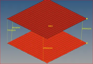
This is rarely used spring but have special role in case of seat belt. It acts like Pulley. In order to create spring3n go to 1D> springs> spring3 and select two node for spring. It also need a plane for orientation so you are going to select three node for plane.

Truss2n:
Truss is also a 1D element which can only go under tension and compression and no bending or torsion. In order to create a truss element go to 1D> rods> element types> TRUSS2N and select 2 nodes.

Beam3n:
Beam is a 1D element which can go under all types of load including bending and torsion. In order to create a beam element go to 1D> bars>element types> Beam3n and select 2 nodes. After that you have to define a plane for orientation. So, select three node to define orientation.

RBE3:
This is most commonly used 1D element for connection between two components so that undistributed force (same force) will transmit. While modeling car system for car crash this is most widely used. To create rbe3 go to 1D> rigids> create>multiple nodes> calculated nodes> select nodes. There is other option too for different form of rbe2.



2D and 3D elements:
2D elements is 3 type's trias, quad and mixed type. Other are also there but only use for surface meshing prior to 3D meshing to get controlled 3D mesh. One things to note over here is that every 2D element node have six (6) DOF. It is because without 6 DOF equilibrium cannot be attained. 2D element is generated only for component with thickness less than 6 mm or the component having varying thickness with complexity.
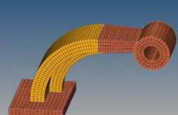
But in our case we are going to create 2D mesh as a surface meshing for 3D mesh. First, we will create 3D Hexa mesh over an arm bracket. So, let's see the process of creating the Hexa mesh.
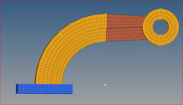
Fig. 2: Final model of Hexa mesh over arm bracket
Step 1:
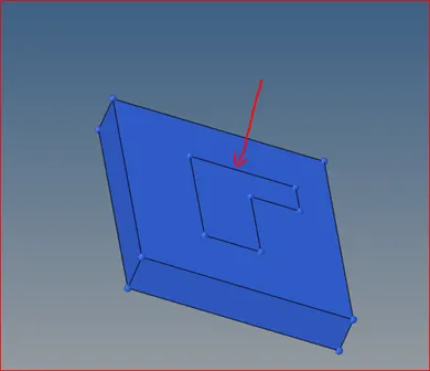
Mask all the surface except base. After masking you'll see the feature line of connected body. So your priority is always to mesh from this side. Because we are going to extend the mesh inside that feature (Pointed by red line).

Step 2:
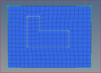
Create a mesh of 5mm size (it depends on your size) with quads only. Remove if there is any trias and smoothen the flow lines.
Step 3:
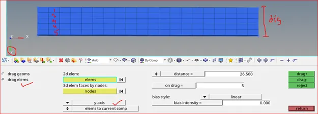
Drag the 2D quad elements created in step 2 for a measured distance and give the value of on drag (5) to create the number of rows during drag. Take care of direction of drag (y-axis) which is very important.
Step 4:
Select the 2D element over the connected area (inside the feature line) when you are in spin elems.
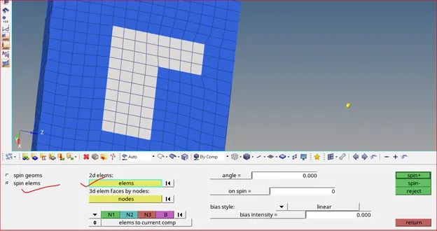
Then, give the define angle of rotation and number of rows of elements required (on spin) and also choose appropriate axis of rotation.
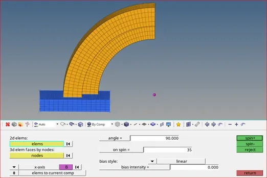
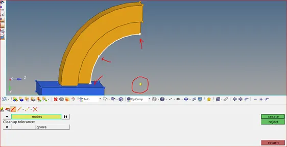
Now, in order to create a center of rotation. Go to Geom> nodes> select arc center and follow the step given below:
Hover the cursor around the line and then line turns into white.
After that tap at three point to create temporary nodes and then press create to create arc center.
Step 5:
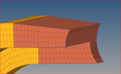
Now, the complexity is here but simple. In this case the simple drag option will not work as intended because of tapered shape. So, what? You have to create an element in such a way that number of element at the destination face match exactly with source element. The orientation and pattern must be in consonance too but element size can be varying.
Now, in order to drag element from source. You need 2D element because 3D elements can't be used as reference for drag. So select the first row of element to turn into 2D element.
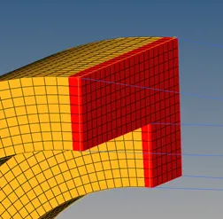
Now, go to 3D> line drag> and select the elements on the front face only (not side or other side face). Then, select the line to give a direction and then drag it.
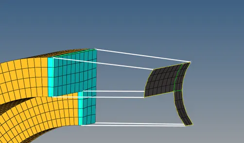

Step 6:
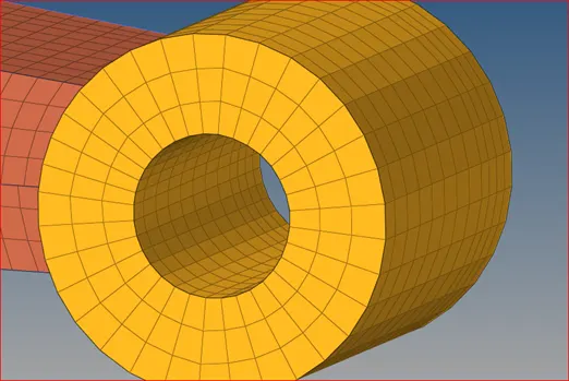
This is a bit eccentric type of meshing because we are not going to drag the element from the previous element. The only way is to mesh the one side of the boss and drag it in controlled manner. In below picture, three black arrows are shown where the surface is crated to match the number of elements with the previous elements. And, the arrow pointing downward which is blue in color is showing a number of nodes, to match the number of elements while dragging with the previous one.
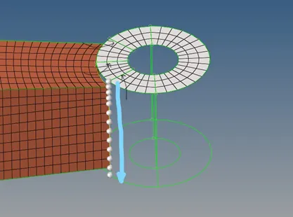
To perform this operation, go to 3D>Solid map> line drag then select elements and drag along nodes as shown below:

Enumerating the stress wave transmission on rail:
Before talking about stress wave transmission on rail. Let's talk about stress calculating method in one and consecutive elements. So, when the external load is applied on the element it calculate the displacement induced on each node after that it calculate the stress corresponding to the displacement induced. Now, before displacing the node the displacement on the consecutive element is calculated and then stress and so on. That's why time step control is very important factor which depend on length of the element, density and material stiffness.
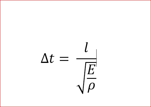
So, using above formula we find the stress passing through the element. Now, using this formula we can find the stress passing along the rail taking average length of the rail (considering rail as single element with equal stiffness and density).
Physical property of element:
E = 210000 N/mm2
G/cm3
l = 1000 mm
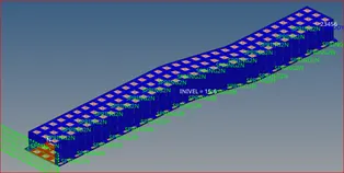
After doing analytical calculation, you will find = 0.193 ms which is a time to travel the stress wave. So let's see this in picture to better understand.
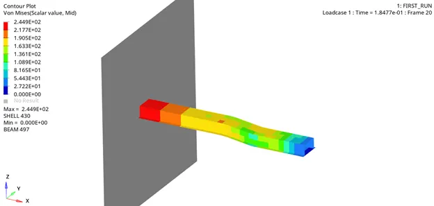
In this case, there is no deformation because we have simulated only for 0.193 ms. If we go furthur by increasing time then for sure we will get deformation value. Check th below animation to distinguish the previous one.
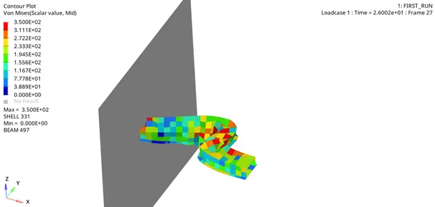
How to achieve this? What do we really need to change to get these difference?
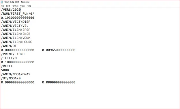
The answer is inside the engine file (_0001.rad) which contains all the engine setup like run time animation frequency, animation request, time history, restart file, time step and other information.
How it look like?
Let's look at each card
/RUN/FIRST_RUN/0/ decoded as /RUN/ENGINE_FILE_NAME/RESTART_FILE_NUMBER/
But in our case there is no restart so 0 in place of restart file number.
0.193 is a run time.
/ANIM/VEC/…. & /ANIM/ELEM/…. is an animation request.
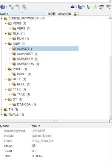
/ANIM/DT have two number. First is a time to start the animation. For example, you want the animation to be recorded only after certain time then you will use this. Second is the frequency of generating the animation. For example: In this case the run time is 0.193 and we want to generate only 20 animation from t=0 (initial time) then in that case we just divide the run time by 20. So, the resulting value 0.00965 MS (frequency = time interval) will give 20 animation file.
/PRINT/-10/0 dictate that print calculated value on each 10 cycle and 0 is a default value for printing variable name (Header like K. energy, Error etc.)
/RFILE/5000 mean write restart file on every 5000 cycles
/DT/NODA/0 is a default 0 and first value represent scaling factor (to scale time step in case of anomalous) while second value represent minimum time step (if time step fall below this then scale factor will be activated which in this case is zero).
You can also tweak the value from Hypermesh window:
Learning Outcomes:
- Role of engine cards in simulation
- Importance of time in the explicit simulation
- To determine time step and predicting the time acquired for simulation
Conclusion:
Stiffening the base of simulation software is the best way to start the project work. It helps one to gain better control and save time and enhance the simulation performance.