Week 3
Aim: To mesh all the parts of the Hood and give a detailed description of meshing and subject thickness to the mid-surface and eventually make the FEA, Draw as a shell.
Input Parameter:
Target Length: 5, Min. Length: 2, Max. Length: 7, Aspect ratio: 3, Warpage: 15, Skewness: 45, Jacobian: 0.7, Min. Quad angle: 45, Max. Quad angle: 135, Min. Tri angle: 30, Max. Tri angle: 120, Tri perc. : 15%
Details:
These sole components have 4 parts in total. So the middle surface is generated exclusively for each part using the offset manual mid surfacing method. The offset distance is taken half the width of each part. Here, it is depicted below:
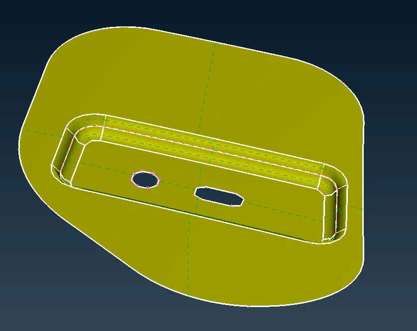
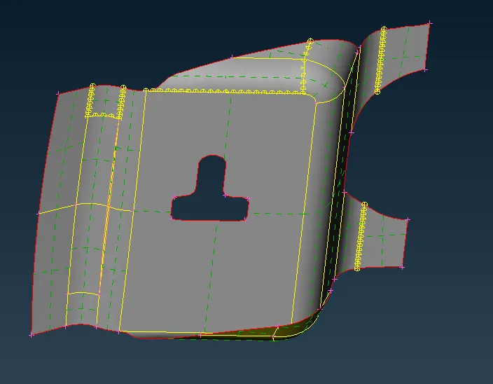
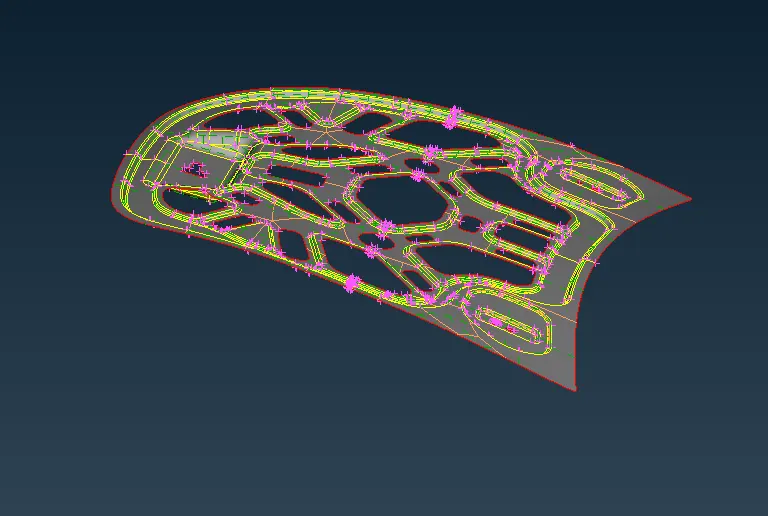
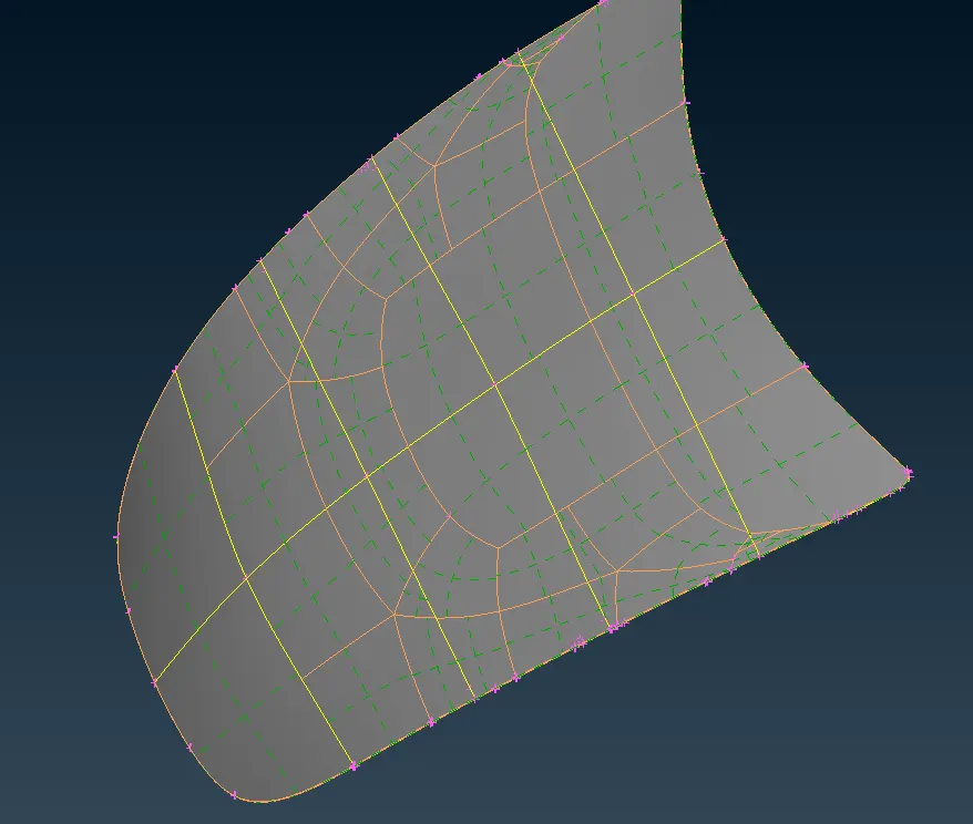
Figure [1]: 4 Parts Middle surface (Manually created by OFFSET)
Pre-Meshing:
The quality parameter is set as given. Similarly, the mesh parameter is also set.
Geometry Clean-up & Meshing:
- Lock_part (First two depicted figure): In this two-part much geometry clean-up was not required. Only in the slope region, two lines were running so close which was failing the minimum length criteria so I took the middle curve ( topo> curves>Middle). Then after, the generated middle curve is projected on the surface to make cons (topo> cons> project). Holes nodes are checked and refined to the even number of nodes.
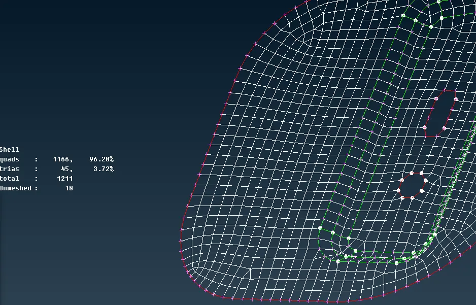
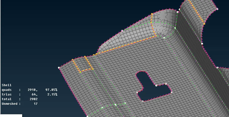
Figure [2]: Small Lock parts meshed
From the above-shown figure, the Percentage of trias is lower than 4%. On the left side, UNMESHED is also delineated in the picture that is because the FEM model was isolated from the middle surface. So now FEA is no more dependent on the middle surface and thus the middle surface is captured as an unmeshed part.
- Upper_Part ( Last figure of Figure [1]): Every surface on this was plain except at the corner with multiple lines failing to meet the minimum length criteria so the middle curve is generated and projected on the surface and others are joined. The upper face was also disintegrated in too many parts so that is joined and a new straight line is scribed from one end to the other abreast breath.
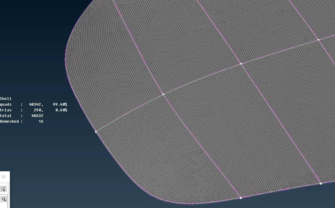
Figure [3]: Upper Meshed Parts
Figure [3] clearly imparts that the number of trias is very small in number (0.68%). The number of trias touching the edge was also eliminated. UNMESHED shown here is due to the isolation of the middle surface from mesh (FEA).
- Lower_Part (Third figure in FIGURE [1]): This is the most intricate part as it has lots of bending and uneven surfaces. It has lots of CRACKS and small faces which prompted lots of deviation from quality criteria. Some of the faces is tackled and solved and others were arduous for me to replace with new desired faces.
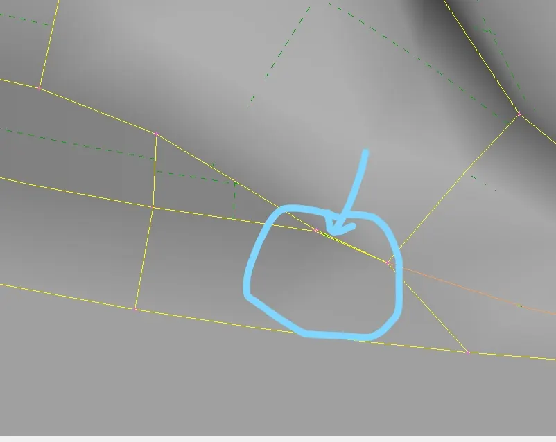
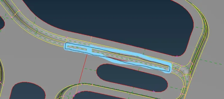
[a]: Small faces (but didn't create an issue during mesh) [b] Two joined surface was uneven so both surfaces were deleted and new was created (topo>faces>new>coons)
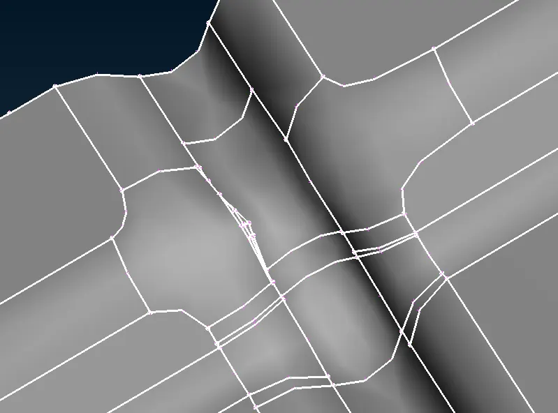
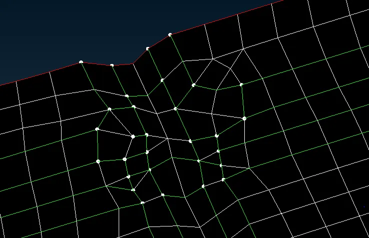
[c] Bent part actual figure failing aspect ration criteria and others [d] Geometry clean-up is done and meshed
Figure [6]
Eventually, this part was removed from the OFF element and meshed with little deviation from an actual CAD design.
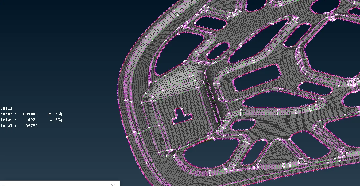
Figure [7]: Lower part of Hood meshed with minimum trias (less than 5%)
Learning Outcomes:
- How to disengage the cons and hot-points and manage cracks. It is the main point.
- Familiarity with selection tools
- Remembered a lot of commands. Due to repetition and solving the challenges for getting good mesh.
Conclusions:
Due to quality constraints, I had to go in a disciplined way which is what allowed me to learn more from this challenge. "How to resolve the slope part and bent part and mesh it well" is the best part of this challenge.