Assignment 1
Aim: Perform a geometry clean-up before and after the mid-surface extraction and ignore the holes with a diameter less than 5mm and hence assign the proper thickness after meshing the component.
Criteria:
Target length: 5mm
Minimum length: 3.5 mm
Maximum length: 7 mm
Components:
- practice 2) Clip repair 3)Mounting Bracket
Introduction:
In this section, we have used a simple part. There is 3 small part to generate the FEA model. So detailed description of the process is delineated from beginning to the end with the different key used for the process. Below is the component is shown on which we are going to work:
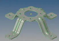
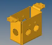
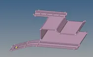
So, let's look at each component step by step:
Geometry Cleanup:
Initially, when we import the CAD geometry we have to check the topology of the surface. This is necessary because while extracting the mid-surface one can expect good outcomes. On the other hand, when you create a 3D mesh you need an enclosed volume so geometry checkup and cleanup is the complementary process.
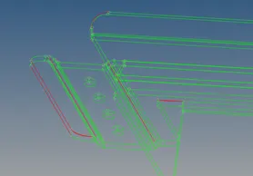
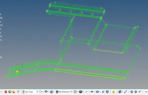
Fig.1: (Left) topo issue which is corrected (Geometry>toggle) and (Right) proper topology
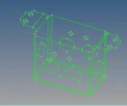
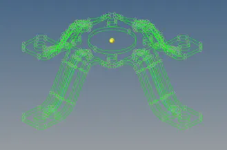
Fig.2: Proper topology of the model without any red line
Mid-surface extraction:
Here, you have to decide on whether to extract a mid-surface or not based on the thickness of the component. If the component thickness is lower than 5mm then extract the mid-surface otherwise solid meshing will be the best practice method. In our case, all component thickness is lower than 5mm so mid-surface is extracted using Geometry> mid-surface> skin offset method.
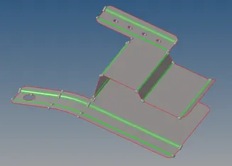
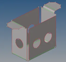
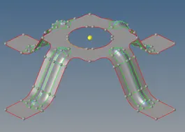
Fig.3: Showing the mid-surface without cleanup
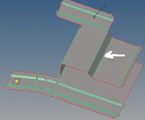
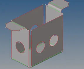
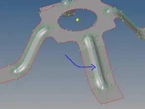
Fig.4: Mid-surface cleanup is done (diameter <5mm is ignored & feature line failing to meet minimum length is suppressed (Geometry> quick edit> toggle))
Mid surface cleanup is done to avoid unnecessary failure of the element. This is a very important point that needs to be considered as the element fails mostly due to minimum criteria can lead to cost the simulation time. Another failure can generate unnecessary stress and give a crap result. So, these points are crucial while modeling the component.
Meshing:
Mesh is the FEA approximate estimation of the real CAD model. Finer the mesh more accurate the representation of the CAD model. Here, in this case, the mesh is a bit coarse with a big element size. Hence, the feature is captured more approximately.
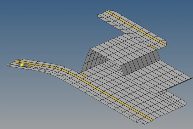
Fig.5: Mesh of the part 1 component
There is a total of 66 failure elements in the fillet region. Here, I conceded the failure elements just to preserve the feature of the component. Otherwise, you can see below the feature seems to be removed and all surfaces aligned at the same plane.
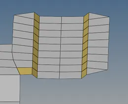
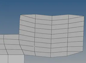
Fig.6: Depicting the difference of removing the feature at fillet area
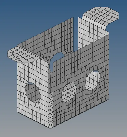
Fig. 6: Part 2 mesh of bracket.
This part is almost rectangular. Thus, it can mesh with quad only but due to the presence of holes, some of the trias are prompted to avoid the formation of rotating quads.
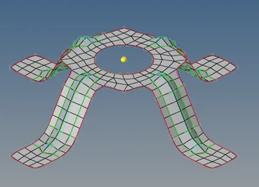
Fig. 7: Part 3 mesh
This component has symmetricity. So the symmetry of the component is taken to reduce the time and work. Below you can the crude mesh rotated through 90 degrees 4 times.
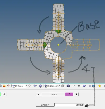
Fig. 8: Rotating the symmetric part of the mesh using (Tools> rotate> elements)
The base of the rotation is created using the Geometry> node> arc center and selecting three nodes. By opting for this option, in this case, some gap is created in between the mesh due to non-uniformity in the mesh. So, some additional work has to be done to get a better mesh and removing the gap.
Assigning thickness:
Assigning the actual thickness of the FEA is of utmost importance. As it plays a vital role during the crash simulation to perform contact simulation. Assigning the actual dimensions of the component helps in calculating the minimum gap between the contacting surface thus actual behavior will be simulated and reliable results will be obtained.
Learning Outcomes:
- Method of meshing and best practices of meshing
- The benefit of assigning the proper thickness of the component
Conclusion:
It is always good to follow the best practices during modeling to get a better result during the simulation.