Week 6
Aim: Implement the FE representation of the connection part on the rear door FE model with the appropriate reasons for assigning.
Introduction:
A system in itself has a lot of sub-systems connected by means to perform tasks sequentially and synergistically. To simulate this connection one needs the FEA representation. The FEA representation helps us to substitute the physical world connection. That might be a welded component for rigid connection, bolted components for rigid or flexible connections, and some for the kinetic representation of the parts.
Procedures:
The following step is followed to employ connections in various parts:
- Where (Selecting an appropriate place to employ)
- What (Types of connection i.e. spot weld, bolt, seam weld, etc.)
- How (Like converting 3D points into spot welds, Type of FEA representation)
The most commonly used connection points in ANSA is as follow:
- Spot weld points and lines
- Gumdrops
- Bolts
- Robscans
- Adhesive lines and faces
- Hemmings
- Weld spots and connecting spots
From there, we will only discuss a few of them which is employed in this project during connection. This project includes the simple model of the rear door which mostly has a connection like bolts, spot welds, and bush.
The FEA model of the rear door is as shown below with no connection done. This FEA model is released from the body so that connection can be done without any hindrance (like creating 3D points in the COG of mesh element).
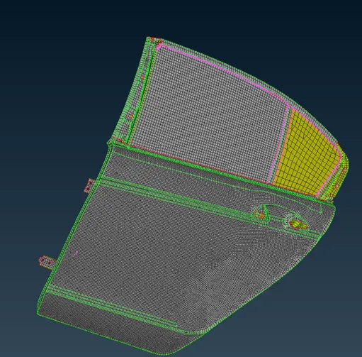
This was a ready-made model so need to perform any topological check-up and mid-surfacing and meshing. Now, we move towards the discussion of the assignment of the connection part separately:
- RBE2 (Rigid Body Elements):
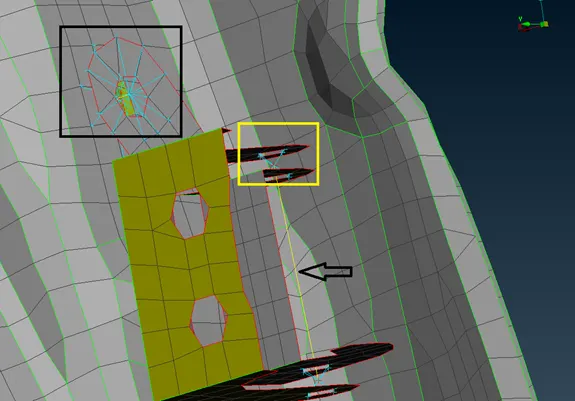
This function is used to create a rigid connection and with the required degree of freedom. This connection can be completely fixed by constraining all degrees of freedom or can be made to translate and rotate in the required direction by releasing some constraints. The picture below is depicting the RBE2 connection. In this picture, two different types of RBE2 have been used i.e. many nodes and two nodes. Many nodes RBE2 is shown by a square bracket in this picture whereas two nodes RBE2 is shown by an arrow pointing toward the yellow line. Many nodes RBE2 is again represented in two forms i.e. cluster form (yellow square bracket) and simple (black square bracket). One can take single or two rows of nodes to form an RBE2 connection so that real-world load distribution will be represented and optionally for this purpose zone cut (not shown here) is also made.
- Spot Welds ( RBE3-HEXA-RBE3):
It is used to represent weld points. There are different types of spot weld used however in this case we used only RBE3-HEXA-RBE3. This spot weld is implemented over the FEA model (meshed component). While implementing this spot weld model do not tweak or reconstruct the mesh so-called mesh-independent spot weld.
This is used where two parallel plates need to be connected with spot type weld. This weld is well depicted in the picture below:
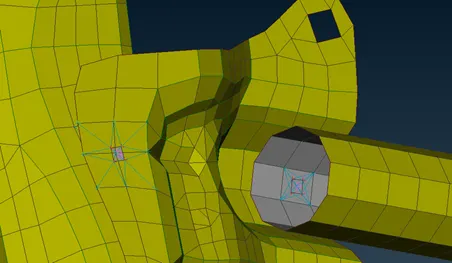
The area covered by this type of weld depends on how one has taken the COG points. This FE representation of spot weld creates Hexa elements and connects the two sheets taken into considerations.
- CONMi (Concentrated mass):
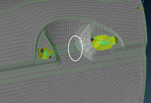
This function is used to create a concentrated mass where required. There are two types of CONMi i.e. general mass and rigid body mass. In this case, we used CONM1 which is generally concentrated mass to create FE representation of Handle mass. The picture below shows the green sphere surrounded by an elliptical line (for clarity) is a concentrated mass.
- Spring and Damper (Weather Strip):
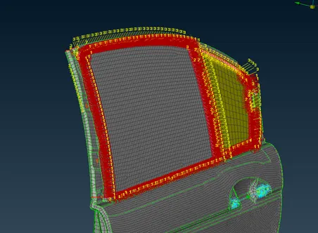
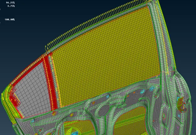
The weatherstrip of the door is represented by using CBUSH elements. In this case, RBE3-CBUSH-RBE3 is generated using a spot line around the glass of the door. It can be represented on geometry and solid and require mesh. The CBUSH is used because it possesses damping co-efficient in all three directions. After the application of CBUSH elements, the glass is subjected to damping element with considered parts. It is represented by red lines which are shown in the figure above. Every generated bush element has its local coordinate oriented randomly and needs to be oriented with the global coordinate system.
Fully Assembled model:
Learning Outcomes:
- The difference between mesh-dependent and independent connections
- Assigning different PIDs to different parts will ease the connection
- Employing appropriate FE representation of connection parts
Conclusion:
Modeling of the connection parts with proper FE representation is inevitably required so one has to know which FE model gives the real and correct representation.