Week 8-Challenge
Aim: Generate 3D mesh of the component by performing topo cleanup.
Introduction:
3D mesh provides us actual FEA model of the component. Thus the accuracy of this mesh is good. But only cons is that it possesses a large number of nodes. Due to this computing time and memory requirement increase. Anyway, in order to simulate the most critical region and a thickness greater than 6 mm demand 3D mesh, according to the thumb rule. So, below we can see the 3D mesh generated in various components using volumetric meshing, manual, and utility.
Geometry Cleanup:
The closed volume body used in this project work is the spare part of the rear-wheel suspension system and housing parts of the machine. These parts are shown below:
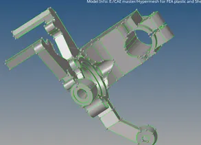
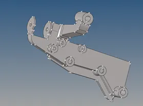
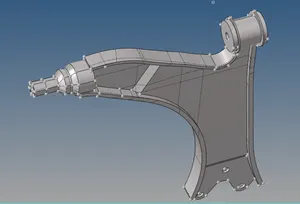
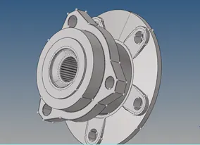
Fig. 1: showing the parent body cleaned with auto clean and manually (Model 1)
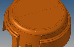

Fig. 2: Housing body is cleaned using auto cleanup and manually (Model 2)
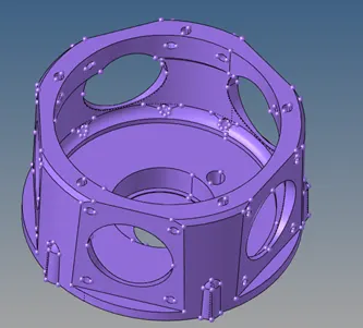
Fig. 3: Crank housing body cleaned using auto cleanup and manual method (Model 3)
Topology Checkup:
Topology checkup is the most important things. As we go through this we can see that some of the feature lines are not connected and appear as single red lines. These lines indicate that the body is not close which creates a problem during 3D meshing.
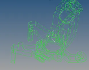
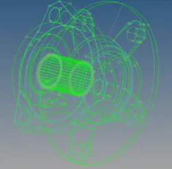
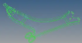
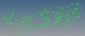
Fig. 4: showing the topology of the model without any errors (Model 1)
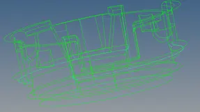
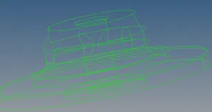
Fig. 5: showing the topology of the model without any errors (Model 2)
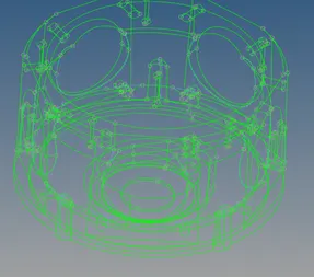
Fig. 6: showing the topology of the model without any error of crank housing (Model 3)
2D & 3D meshing:
In this project each component that you have seen are thicker (>6 mm) so by the rule of thumb it is necessary to mesh those components with 3D mesh. Now, in order to generate good quality 3D mesh, you have to create a controlled 2D good quality mesh. So, in this case, the 2D mesh is created for every component followed by 3D mesh. Except crank housing where the volumetric mesh is applied.
Model 1:
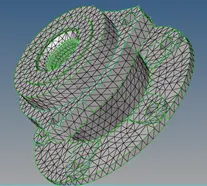
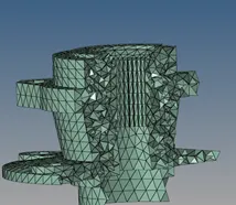
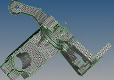
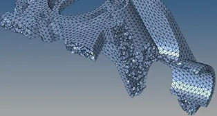
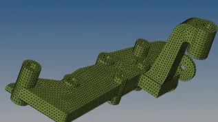
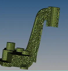
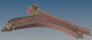
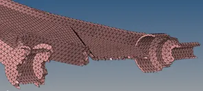
Fig. 7: 2D mesh and 3D mesh of the component with no tet collapse (<0.15)
Minimum length quality criteria are checked for the 2D mesh. At some critical region, minimum length quality failure is compromised. The only quality check for 3D mesh done is Tet-collapse. At curved or bent regions we have used right angled trias whereas on straight surfaces we have used equilateral triangle trias.
Model 2:
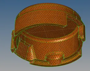
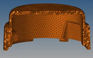
Fig. 8: Housing part 2D and 3D mesh with no Tet-collapse.
Tet-collapse element:
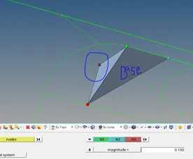
Fig. 9: showing the tet-collapse error (solving method)
Tet collapse appeared at the outer surface. So, this Tet collapse is solved using the translate method. During translation, one node is selected which height is so small, and then pulled away from the base surface. In this way, the height of the tetra element is increased. As you can see in the picture.
Model 3:
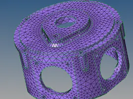
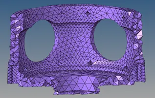
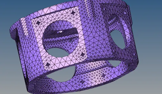
Fig. 10: Volumetric mesh generated in crank housing (with proximity ticked)
Volumetric meshing does not require 2D meshing of the component. The only input we have to give is the criteria for the mesh. Other options can also be used like "Use proximity or on curvature" according to requirement. The implication here is that use of proximity help to capture the feature in a good way by refining the mesh at such region.
Final model:
Model 1:
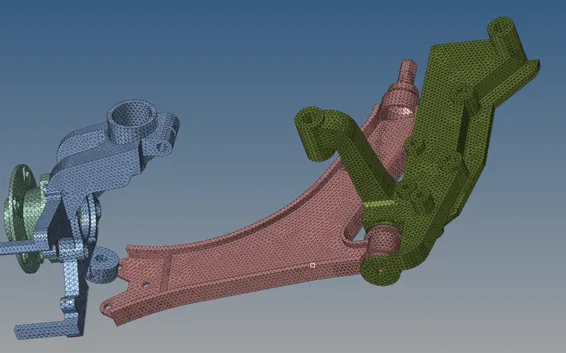
Model 2:
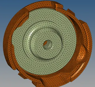
Model 3:
Learning outcomes:
- How to generate 3D mesh using surface meshing, utility, volumetric option
- How to deal with Tet-collapse method with a different approach
- The advantage and disadvantage of different mesh method
- Problem handling method during mesh
Conclusion:
The 3D mesh can be generated using the different methods but the best and more controlled method is indirect meshing using 2D mesh. Free edges must be checked and connectivity of the mesh must be proper otherwise 3D mesh won't be generated.