Project 2
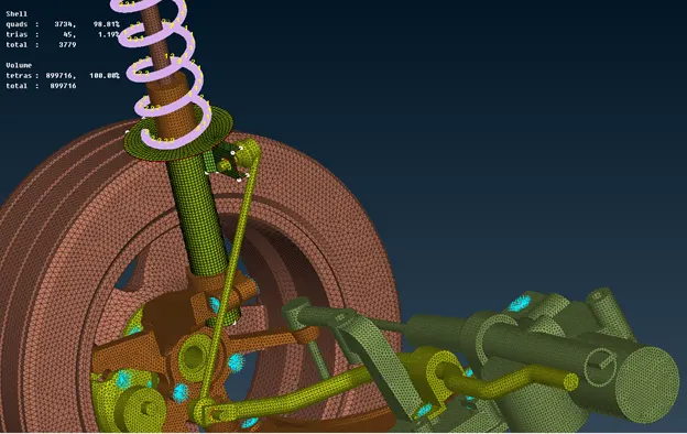
Aim: Mesh the rear wheel assembly of the car using appropriate mesh element 1D, 2D, and 3D with a suitable connection at the required place using the generated FEA model.
For Tyre and Rim:
|
1 |
Target Length 6.5 |
|
|
2 |
Minimum Length |
5 |
|
3 |
Maximum Length |
10 |
|
4 |
Skewness |
45 |
For Mixed element (Mid-surface only):
|
1 |
Target/Average length |
4 |
|
2 |
Minimum Length |
2 |
|
3 |
Maximum Length |
6 |
|
4 |
Aspect |
3 |
|
5 |
Warpage |
15 |
|
6 |
Skewness |
45 |
|
7 |
Jacobian |
0.7 |
|
8 |
Minimum Quad Angle |
45 |
|
9 |
Maximum Quad Angle |
135 |
|
10 |
Minimum Tria Angle |
30 |
|
11 |
Maximum Tria Angle |
120 |
For Trias element (other components):
|
1 |
Target/Average length |
4 |
|
2 |
Minimum Length |
2 |
|
3 |
Maximum Length |
6 |
|
4 |
Skewness |
45 |
For the 3D element:
Tet-collapse 0.2
Introduction:
3D meshing captured the real-world design shape and feature with no assumption which gives more accurate results. 3D meshing is done when the thickness of the body is more than 5mm or when the body thickness is higher. There are two types of elements for solid meshing i.e. tetra and brick meshing. Tetra meshing is done either by the direct method (without surface meshing) and indirect method (First surface meshing then solid meshing). The indirect method of Tetra meshing provides us with better mesh flow and quality issues. Brick meshing is done for critical areas and accuracy. Brick meshing required more time, attention, and patience whereas solution time decreases because the number of nodes compared to tetra mesh is lower with better mesh flow. So, crash and non-linear analysis give preference to brick mesh.
The difference between solid meshing and shell meshing is that solid meshing has only three translational degrees of freedom where shell mesh has six translational and rotational degrees of freedom.
Here, in this report, both solid mesh and shell mesh is used as per aptness. As you can see the element quality criteria are different for a different part for shell meshing but solid meshing, only a quality check is done for Tet-collapse. Though quality checks for solid meshing are done for jacobian, distortion, stretch, and volumetric skew which is not preferred in this case.
Procedure:
- Setting PID (for easiness)
- Geometry cleanup
- Design study
- Choosing types of elements for each part
- Mid-surface extraction (when required) & shell meshing
- Solid meshing
- Quality check-up
- 1D element creation & Connection
- Applying connection
Geometry Cleanup:
As we are going to perform solid meshing in most of the part. It is necessary to check the part are closed volumes with no single cons. Other important aspects to check are crack and triple cons. After executing geometry check some needle face error is faced which is fixed automatically.
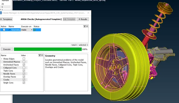
Fig. 1: Showing zero undesired error (At PID MODE VIEW)
Design Study:
The design of the model is studied extensively. Before proceeding to generate the mesh. The feature line and parts are disfeatured at the corner considering minimum length criteria to avoid any such failure. Meanwhile, an important feature is not disfeatured and minimum length failure is accepted at such area. Here, some of the disfeatured areas are shown:
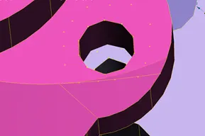
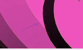
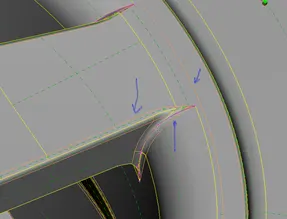
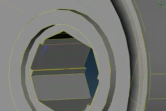

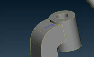
Fig. 2: Depicting the disfeaturing of the body (To element failure at the corner & fillet region)
Another study done over here is the use of a type of element for meshing that particular part. It is we who decide what sort of meshing will be better for those parts. Typically, we use to extract mid surface for a body with uniform shape and thin body. Otherwise, we use solid mesh for better results and feature capturing. So, here is the figure which is mid-surfaced because of minimum thickness and uniformity:
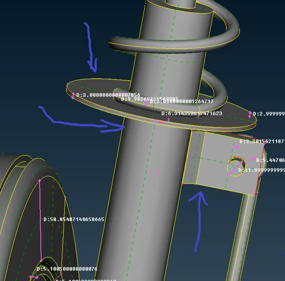
Fig. 3: Parts which are mid-surfaced for shell meshing purpose
After studying the CAD model. The types of elements required for different parts is decided. Now, each part is meshed using the corresponding mesh parameter.
Shell Mesh:
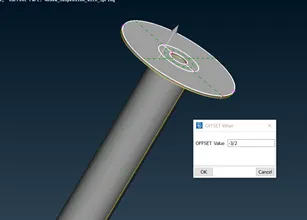
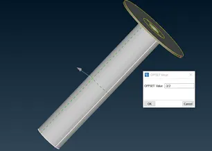
Fig. 4: a) offsetting upper plate by 1.5mm Fig. 4: b) offsetting Damper rod by 1.5mm
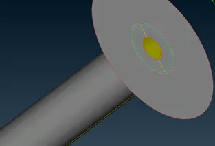
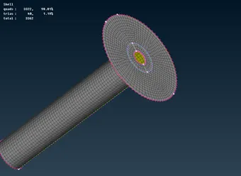
Fig 4: c) Extracted Mid-surface Fig.4: d) Shell meshed
In Fig. 4 (a) the mid-surface is extracted using the offset command (Topo>faces> offset). Similarly, the mid-surface is also extracted for the damper rod (b). Overall mid-surface of this part is shown in figure 4 (c). The cylindrical part is disconnected when mid-surface so the cylindrical part is extended up to the upper plate which forms triple cons.
In fig 4 (d), shell quad mesh is generated as shown for the damper rod and a mixed type of mesh is generated for a circular plate. This mixed type of mesh gives smooth flow without rotating quads.
Number of quads: 3322
Number of Trias: 40
Algorithm: Spot mesh
Similarly, shell mesh is also generated for the bracket.
Solid Meshing:
- Rim:
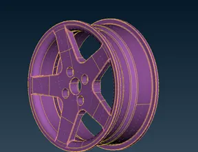
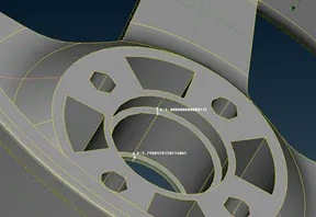
Fig. 5 (a): Rim (MID VIEW MODE) Fig. 5 (b): Feature failing minimum length criteria (not disfeatured)
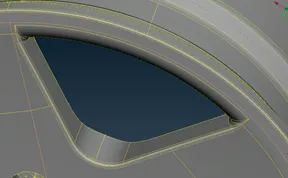
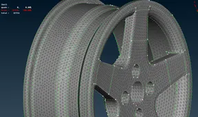
Fig.5 (c): Feature optimization using a middle line at fillet region Fig. 5 (d): The surface meshing of the rim
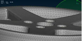
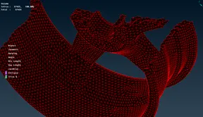
Fig. 5 (e): Checked the Kinks and raised faces on the surface and removed Fig. 6: Solid mesh with no Tet-collapse (Bound View mode)
In this component, as shown in figure 5 (b), the stepped part is failing the minimum length criteria but disfeaturing that reason completely change the design thus it is not disfeatured rather trade-off is done with the OFF elements.
Ortho trias is used for curved region whereas normal trias is used for the plain region. Sometimes, normal trias is used at curved region only if ortho trias filed to captured the region very well.
- Tyre:
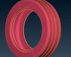
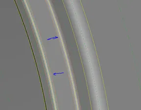
Fig. 6 (a): Tyre Fig. 6 (b): Disfeaturing small fillet (as depicted)
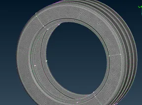
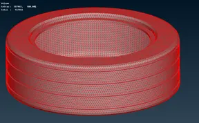
Fig. 6 (c): Created surface mesh (Tetra mesh) Fig. 6 (d) Generated Advanced tetra mesh (Tetra FEM method)
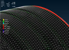
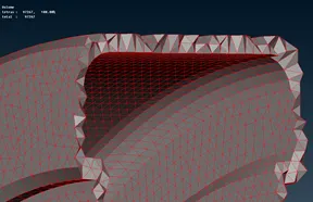
Fig. 6 (e): Failed element at stepped region (not disfeatured) Fig. 7 (f): Inner view of the tetra solid mesh
Tetra-FEM method is used to generate tetra solid mesh. No Tet-collapse has appeared. Some important features are not disfeatured even though the element was failing.
- Other components:
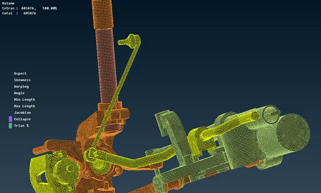
Fig. 7: All other components solid mesh with no Tet-collapse (PID VIEW)
The expanding/ growth rate in the TetraFEM algorithm is low so more often this algorithm is used for structural components with less thickness. That's why this method is opted for creating tetra-mesh for all components.
1D Element:
This is a one-dimensional representation of the joint or other component simulating the behavior of the actual component. All these 1D elements are in-made provided by the software with the flexibility to change as per requirement. Some of these elements are spring, rbe3, rbe3, bolt, cbeam, cbar, crod, and many more. In this project we have used some of these element FE representations as shown below:
- Spring:
The spring is represented in the FE model using the CBAR option (NASTRAN> ELEMENTs>CBAR). By creating COG of the spring middle line, the direction of orientation is marked so it is important to create as shown
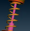

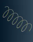
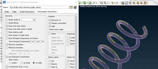
Fig. 8: FEA representation of the spring using the CBAR method
- RBE2:
RBE2 is one of the very rigid representations of the connection. It transfers the same amount of force regardless of the length of the RBE2 from the point of onset to the endpoint. But this is different for RBE3 which transmits force proportionally. Some of the RBE2 connection implemented in this model is shown below:
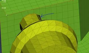
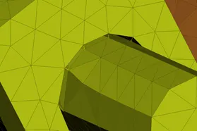
Fig. 9: RBE2 rigid connection
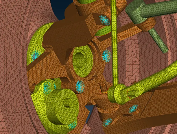
Fig. 10: RBE2 many node representations (blue color web-like structure)
- Seam weld:
Seam weld is the most common to weld two-component mostly in the automotive field because of its proficiency. Seam weld overlap shell is used for connecting two of the parallel component. So in this case double row overlap shell is used.
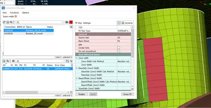
Fig. 11: showing the FE representation of the seam weld
Final Model:
Learning Outcomes:
- To create the solid mesh and avoid feature which might give element failure without losing important feature
- Reason for pyramid element generation
- FE representation of the weld can't be done in between solid and shell mesh
- Proper surface mesh prevent possible failure during 3D mesh
Conclusions:
The solid mesh is dependent on the surface mesh and geometry cleanup and one will get the corresponding result. So, it is good to achieve good surface mesh with no jacobian, warpage and distortion failure, and kink and raised face. The proper study of the CAD is necessary to choose the type of element for simulation.