Week 4
Week 4 Challenge: Bottle Cap
Aim: To perform geometry cleanup and generate mid-surface and create meshing on that respective mid-surface. Also, connote the thickness of each element and draw the FE model as solid.
Procedure:
Generally, after importing the file in ANSA we proceed with the following steps:
- Perform topo on the whole body
- Execute Geometry Check-up
- Geometry Clean-up (if required)
- Generating Mid-Surface and Assigning thickness
- Generating Mesh
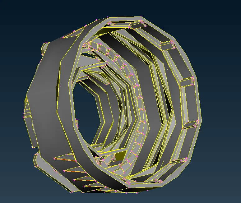
As shown in Figure 1, this component seems to be more complex to understand very well readily. It has a varying thickness in different places and lots of features too. In order to understand and probe the component, the Cutting plane is activated on both top and bottom of the cap. Figure 2 clearly depicts the usefulness of the cutting plane.
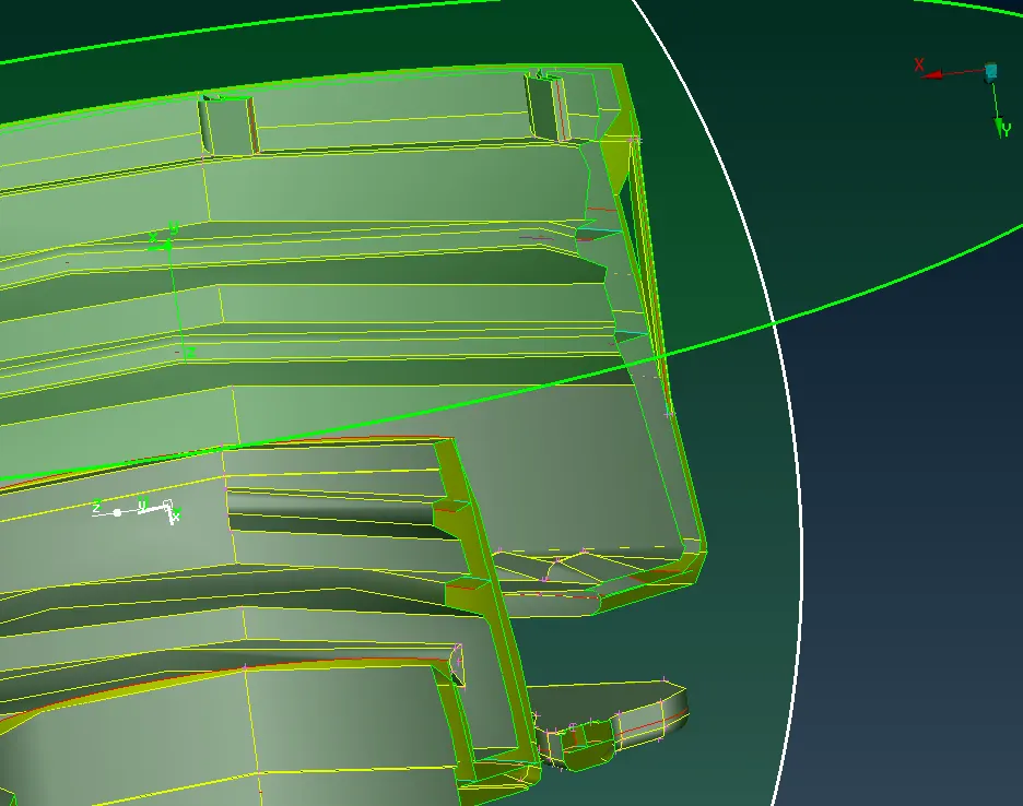
Figure 2 Cutting Plane for decoding
After understanding the complexity and non-uniformity of the body thickness of the body was measured and using WELD POINTS. After taking thickness measurement, the whole body is compartmentalized into 14 parts and a new PID is defined for every 14 parts according to the thickness.
Now is the time for generating mid-surface for each part. Preferably mid-surface was generated from the bottom surface to top. Here it is described below:-
- Lower Base (with and without FE):
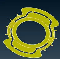
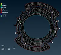
The percentage of trias is taken care of here and reduced to 6 %. Opposite trias is also eliminated. Rotating quad is reduced down to a minimum but a little concession. OFF element is totally eradicated. Unnecessary hot-points were also removed so that unusual mesh elements will not be generated.
Mid-Surface: Generated using an offset of 1.62/2 from the selecting bottommost part.
- Auxiliary base:
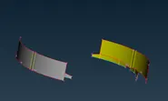
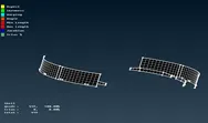
It is a perfect shape. It does not have any circular or sharp bend so trias formation is 0% without any OFF element.
Mid-surface: Generated using face> middle (single).
- Upper Base and Triangular feature:
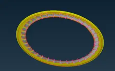
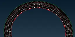
The percentage of trias in this part is 3.54% which is due to a circular shape with OFF element 2.56%. OFF element is prompted due to the existence of triple formed by feature as the relation between the two body parts. Indeed, the distance between the inner circular edge and hot-points of triple cons becomes less than minimum length criteria leading to quality failure. However, it is acceptable where such a condition arises but only minimum length failure is acceptable in some cases.
Middle-surface: Generated using topo> offset> 1.02/2 from topmost part for base. For feature followed https://skill-lync.com/knowledgebase/how-to-extract-mid-surface-in-complicated-area.
- Spiral Patterns ( on inner and outer circumference):

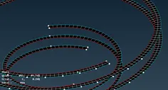
This spiral is rectangular in shape so the mesh formed is almost quad in shape however 0.24% of trias is stimulated due to spiraling nature. OFF element is zero.
Mid-Surface of this one is generated using top> curve> middle and then that middle curve is projected on the middle surface of the outer circumference. Then face> new and the new surface is generated between the middle curve and projected curve.
- Circumferential Part:
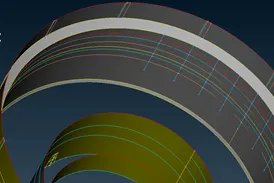
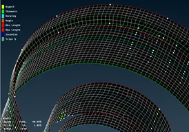
The percentage of trias in this part is 1.01 % where opposite trias is eliminated and the rotating quad is removed. due to multiple triple bounds over the outer circumference, it was a bit difficult to gain the desired quality but with careful geometry cleanup and meshing gave better results. OFF elements are nullified.
Mid-surface: Generated using an offset of 1.22/2 for the upper part of the outer circumference and 1.02/2 for the lower part of the outer circumference. Similarly for another circumference with corresponding thickness.
- Inner Ribs:
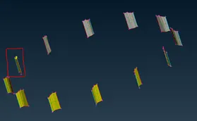
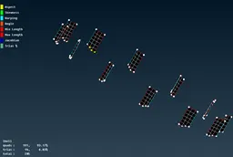
The percentage of trias is 6.83 % due to slant surface and no rotating quad is present and the OFF element is zero.
Mid-surface: Generated using topo> faces> middle>multi. Then it is rotated using transform> copy> rotate at an angle of 360/ 11. The parent surface is depicted in the picture shown above.
Meshing:
In this case, spot meshing is used. Though spot meshing is used for WELD and Connecting part for better results and more elements, spot meshing is done because it possesses lots of macro areas. Indeed, it is suitable.
Problems arises and their Solutions:
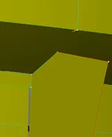
Here you can see a cut on the surface is made. That cut is made because there was a very small surface congested between thus creating single bounds and triple bounds with lots of hot-points. Due to this reason mesh concentration was too high in those regions with lots of quality failure.
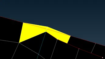
Here is the ASPECT RATIO problem along with minimum length quality failure. This is occurred due to the minimum length between the triple bounds hot points and edge of the circumference. This problem was solved by creating a new surface which eventually imprinted triple bounds on the circumference and filled the gap as shown below:
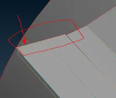
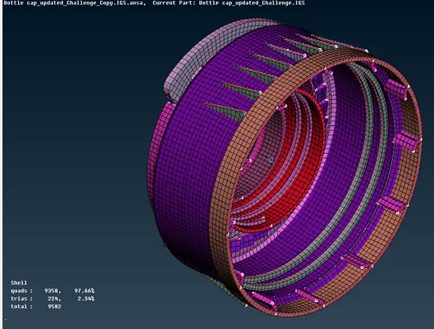
Final results have shown:
Figure 3 Draw shell as solid mode representation
Learning Outcomes:
- How to copy the body in a circular pattern
- To use Cutting Plane for a proper understanding of the component complexity
- Selecting Proper Side for offset during mid-surface creation
- To deal with collapsed cons and unnecessary triple cons and hot-points
Conclusions:
Complex part need to be disseminated into a smaller part for a proper understanding of the design and minimum length failure criteria is acceptable at the narrow place and some tweak in the feature can be done to eliminate the quality failure.
References
- https://skill-lync.com/knowledgebase/how-to-extract-mid-surface-in-complicated-area.
- ANSA_User_Guide.pdf