Project 1
Aim: Perform the geometrical checkup of Ip Substrate, create a mid-surface using the best method, and reason it then meshes and checks the quality of element with the given quality parameter.
Quality Criteria:
|
1 |
Target/Average length |
4 |
|
2 |
Minimum Length |
2 |
|
3 |
Maximum Length |
6 |
|
4 |
Aspect |
3 |
|
5 |
Warpage |
15 |
|
6 |
Skewness |
45 |
|
7 |
Jacobian |
0.7 |
|
8 |
Minimum Quad Angle |
45 |
|
9 |
Maximum Quad Angle |
135 |
|
10 |
Minimum Trias Angle |
30 |
|
11 |
Maximum Trias Angle |
120 |
|
10 |
Trias Percentage |
15 |
Introduction:

Figure 1 Ip substrate
Numerical analysis of the component and complex parts is increasing the durability, reliability, safety, and decreasing the cost. Due to this method, there is a tremendous decrease in time. Thus, making the production more and more gainful.
Figure 1 showing the front part of the car from inside. In this project, the simple design of this part is used for meshing. This part has lots of small features and bending which impose a challenge in creating mesh perfectly and smoothly as desired. That's why some trade-off is maintained between quality failure and the feature of the component. Another challenging thing is trias which is large in number due to multiple converging micro areas. Smooth flow of mesh in converging micro area is only feasible due to trias mixed with the quad. Hence, trias is not only disadvantageous due to stiffer but also advantageous.
Methodology:
- Geometry clean-up
- Mid-surface extraction (comparison)
- Measurement (between feature line)
- Disfeaturing
- Meshing
- Quality check-up and correction
Geometry Clean-up:
It is the prime importance for any model or any numerical simulation. After importing the CAD files mostly in.IGES format. There is a lot of typos and extra faces, needle faces, and cons. These are a CAD design flaw. Most CAD software does not have features to clean-up these typos. However, FEA software has embedded a wide variety of tools to deal with these problems. Some of the typos are shown below:
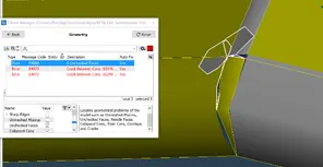
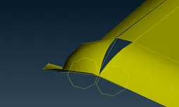
Fig. 2: Extra-faces on the surface
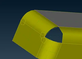

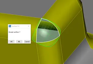
Fig. 3: Deleting additional surfaces and creating new surfaces
Mid-surface Extraction:
This is a single component with the same thickness all over the part. On the front side of this component does not have any features and ribs but on the backside lots of features and rib is made to make the design more strong structurally.
Initially, the mid-surface extraction is done using the casting method (Topo>Faces>Mid. Surface> Casting). As it is known that the casting method cannot capture all features properly and some of them are completely ignored and so is true in this case too.
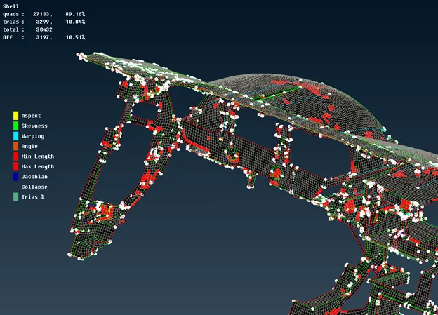
Fig. 4: Mid-surface extraction using the casting method (Exceedingly quality failure & disfeaturing)
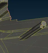

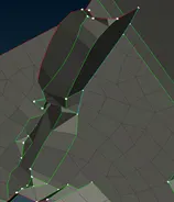
Fig. 5: Failure to capture feature using casting
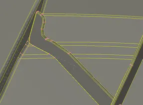
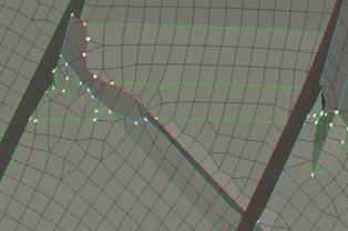
Fig. 5 depicting an improper way of capturing ribs (casting deficiency)
All these deficiencies are overcome by using the manual mid-surfacing method. It consumes more than casting. It also requires some finishing like extending and projecting and checking properness but the desired mid-plane can be created and modified. This method is more flexible.
First: Mid-surface of the main body of the component is taken by offsetting it by half the thickness of the component from outside as there is a lot of feature inside (create lots of holes and cut face).
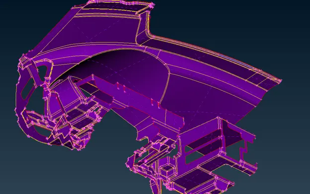
Fig. 6: Extracted mid-surface of the main body without feature
This method seems a lot easier. Now the only thing left is to disfeature some fillet area and extract mid-surface for each feature. This is the most time consuming where one needs to draw attention because this step decides what sort of mesh and failure you will obtain after meshing.
Second step:
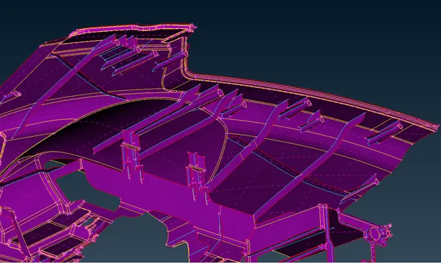
Fig. 7: Mid-surface of feature and body
Mid-surface is extracted using the middle option (Topo>Faces>middle) and sometimes using offset (Topo>Faces>offset). Precaution must be taken during this step. While creating a middle surface and then extending over other surfaces some extra hot points form or incomplete extension occur or disappear from the surface (some cutting bring the surface back).
Here is the one problem that I face after deleting the extended mid-surface. Some part of the cons were left over there as single cons as shown:

Fig. 8 a) single cons with single hot points b) Inserted points on other end c) Gave topo and cut the double cons
failure occurs. At such conditions, the fillet is suppressed taking mid-line and making a sharp edge. Otherwise, one has to decrease the element length a little more at the cost of solving time.
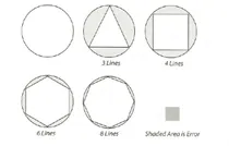
Fig. 10 showing the effect of decreasing element length (courtesy: Practical finite element analysis (Book))
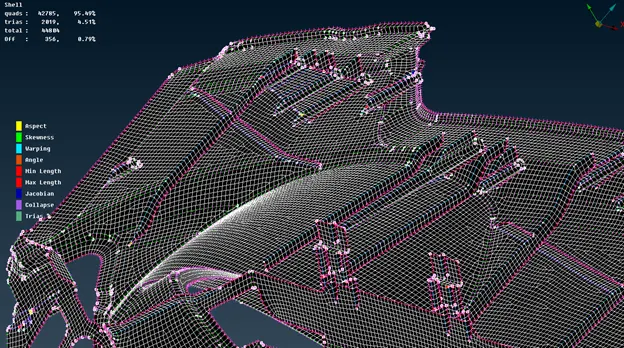
Fig. 11. The optimum mesh is generated manually using spot weld (mixed type)
Initially, all features were selected to mesh each by each. Then the main body part has meshed. This way it is easier to sort out the problem in the feature during mesh. So that whenever modification or alteration is required will be done without erasing the mesh of the main body.
From the above figure, you can see the number of trias is huge in number (2114 trias) which is due to lots more converging section. Triple bounds are another reason for decreasing the option to decrease the number of trias. Triple bounds is also a major factor for the generation of failure elements. Other reasons for failure elements are the feature which must not be disfeatured.
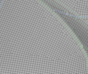
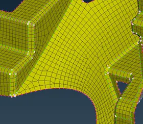
Fig. 12: Converging micro area prompted trias element (for smooth flow of mesh)
All trias are aligned in one direction and opposite trias are resolved and trias perpendicular to each other are resolved somewhat and some of them were not resolvable because it was forming rotating quads. Rotating quad is not preferred for crashworthiness analysis whereas it is acceptable in structural analysis.
Draw shell as Solid:
Different colors in the figure below represent different thicknesses.
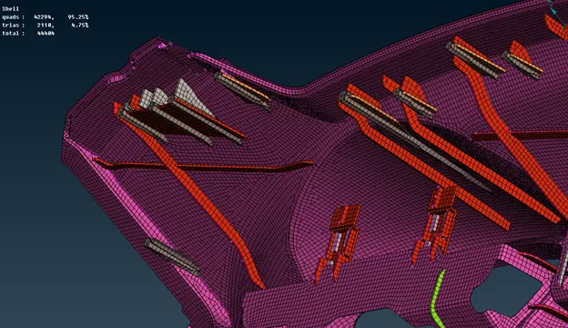
Fig. 13: Final component FEA model in solid element form
Learning Outcomes:
- Method to extract mid-surface of large complex part
- The benefit of meshing feature before the main body part
- The benefit of assigning PID & thickness of mid-surface instantly after extracting
- The casting method gives an idea to create a mid-surface of the intricate part (even if that is not perfect).
- Trias in the mesh is ineluctable in the case of converging micro-areas.
Conclusion:
The trade-off can be maintained between OFF elements and features of the component to obtain better mesh flow and quality. While generating the FEM model of the complex and large component it is good to switch between automatic and manual methods. If the automatic method provides us better results with less modification then opting manual method is not necessary otherwise.
References:
- ANSA_User_Guide
- Practical finite element analysis, Book, Nitin S Gokhale, Sanjay S Deshpande, Sanjeev V Bedakar, Anand N Thite