Week 9-Challenge
AIM: Mesh the given model with the appropriate mesh parameters and create a connector to attach various parts of the model.
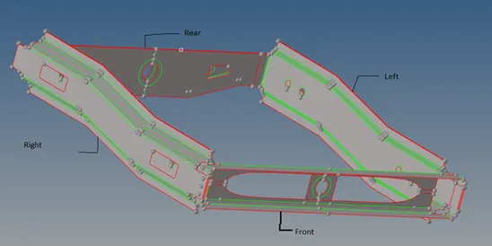
Introduction:
The connection is one of the separate parts of FEA modeling. It plays a crucial role to represent the real-world connection. There is lots of option available to simulate the real-world system. Where in this particular report we are going to use some of the most widely used connections in the automotive field. The most cautious thing here is that modeler needs to give actual input for the connection otherwise simulation might not be right and give a crap result.
- Right rail 2 and Front truss 1:
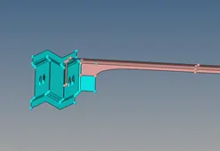
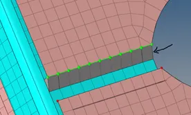
Fig. 1: Seam-Quad (angled + capped + L) implemented (Right side)
Seam weld is most widely used in the automotive industry due to its reliability and strength. It is a continuous weld used to connect two parallel and orthogonal surfaces. Here, we have used a parallel quad seam weld. The representation of the quad seam weld is shown below:
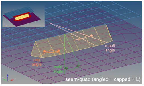
Fig. 2: Details of seam quad (courtesy: Altair Hypermesh)
2. Left Rail 2 & Front truss 1:
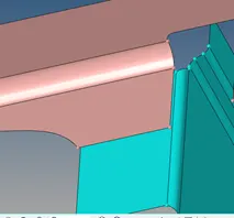
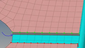
Fig. 3: Seam quad
This weld is performed between the two surfaces.

3. Front truss 2, Front truss 1 & Right Rail 1:
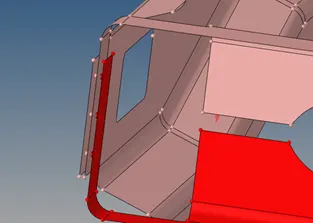
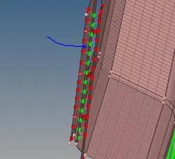
Fig. 4: Spot weld with 3 Layers and 5 mm in Diameter

Fig. 5: Panel to create a spot weld
4. Front truss 2, Front truss 1 & Left Rail 1:
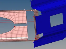
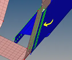
Fig. 6: Hexa (Adhesive)
To represent adhesive. Seam weld of Hexa type is used. In there you have to define parameters like spacing, tolerance, strips, coats, and width.

Fig. 7: Seam, Hexa (Adhesive) subpanel
5. Rear truss 2 & Right Rail 2:
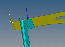
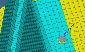
Fig. 8: Bolt Connector
Bolt connection is also the most widely used connection in the real world. That's why there is an option particularly available for different types of bolts (connectors> bolt). In this case, you have seen that the actual model does not have a hole for bolt connection. So, in such a case, one must switch to "create a hole if none". This generates hole and bolts connection at a given place on the FEM model only.

Fig. 9: Bolt (Create hole if none) subpanel
Similarly, the bolt connection is made between the Rear truss 2 and Left rail 2.
6. Right Rail 1 and Right Rail 2:
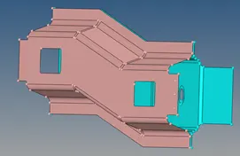
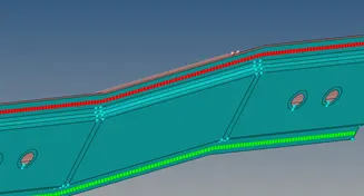
Fig. 10: Spot weld with rigid links
Spot weld with the rigid link is created in the above sheet metal part using CONNECTOR>> SPOT>RIGIDLNK option.

Fig.11: Spot weld with rigid link subpanel
7. Left Rail 1 and Left Rail 2:
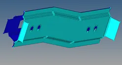
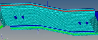
Fig. 12: Spot weld with spring type

Fig. 13: Spot weld with spring-type subpanel
Learning Outcomes:
- How to implement different connectors and debug (like varying tolerances, spacing etcetera)
- The difference of different variables like width in seam Hexa (adhesive) and tolerances and so on.
Conclusions:
The connector is the important FEA model for the representation of real-world connection behavior. So, it is very important to realize the connector inappropriate manner with controlled variables to get actual results.