Week - 3 Drop test Challenge
Drop test of mobile Using LS_DYNA
Introduction:
Drop test is most widely used for fragile material. This test provides some certainty in impact strength. It gives an idea about how the sudden surge of force is transmitting through the body. You will also come to know about the critical area of stress. By testing the fragile product at different angles will also provide us knowledge of impairment at some side. Thus, this information is of utmost importance, especially in evolving mobile industry.
Therefore, we are going to check how the stress is distributed due to impact force and effective time for stress.
Model preparation:
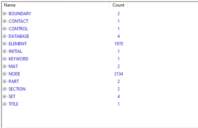
These are the keywords that is used in this model. There are two-part, one is mobile itself and the other is a rigid body. So, the mobile is supposed to fall down with an initial velocity of -10 mm/ms (-ve direction is due to the coordinate system). As the mobile proceed and hit the rigid wall, it requires contact to detect another part otherwise it passes through. So, contact is prepared using "*CONTACT_AUTOMATIC_NODE_SURFACE" card making mobile as slave part and rigid surface as master part. More often we apply boundary conditions to the body to avoid numerical instability but in this just a simplification of the model. We are applying boundary conditions on the mobile in all DOF except z-direction (direction of falling). The rigid plate (another part) is constrained in all DOF.
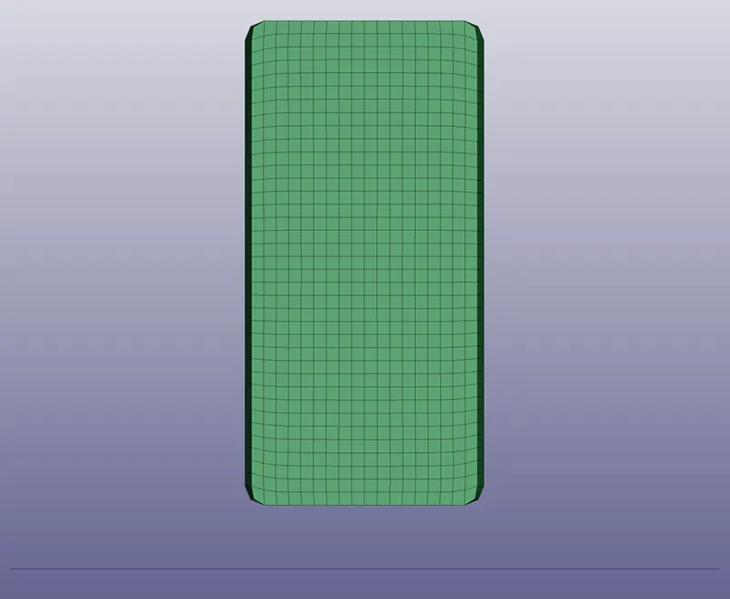
Now, if mobile hit the rigid body, we obviously want mobile to sane output. For this, material behavior is the most important thing. To define the material, you have to check the element type. In this case, mobile is assumed as whole solid and meshed with Hexa element. The element formulation used is a fully integrated solid element to avoid hourglass energy formation (section> solid). The material card used for mobile is ISOTROPIC_ELASTIC_PLASTIC with density (0.00805 g/mm3), shear modulus (8.3 e4 GPA), and bulk modulus (1.6 e5 GPA). The rigid wall is of shell-type so the element formulation used for this one is Belytschko-Tsay which is a default material. The material card used for this is "*MAT_RIGID" with properties, the density of 0.027 g/mm3, the elastic modulus of 6.9e4, and Poisson's ratio of 0.33.
As we are doing the simulation work with an algorithm, thus computer does not know when the event will end. So, it is good to terminate the simulation using control cards.
Analysis:
The setup is made as the mobile is allowed to move in only one direction so when the mobile hit the rigid wall it can translate in only one direction before and after. To check if the model is correct, we need to probe energy of the system. The energy plot is shown below.
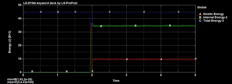
From the above plot, we see that the kinetic energy is almost constant for 1.9 ms then after the kinetic energy suddenly dropped to the lowest value which is due to the collision. Then after again mobile bounced back and restored some of the kinetic energy. If you see the corresponding internal energy value then you'll find that internal energy is quite opposite to kinetic energy. The total energy of the system provides us information on how accurate our model is. If total energy is not conserved then it means there is some error in the output due to several factors like hourglass energy, contact energy or penetrations, and so on.
From the above plot, we see that the kinetic energy is almost constant for 1.9 ms then after the kinetic energy suddenly dropped to the lowest value which is due to the collision. Then after again mobile bounced back and restored some of the kinetic energy. If you see the corresponding internal energy value then you'll find that internal energy is quite opposite to kinetic energy. The total energy of the system provides us information on how accurate our model is. If total energy is not conserved then it means there is some error in the output due to several factors like hourglass energy, contact energy or penetrations, and so on.
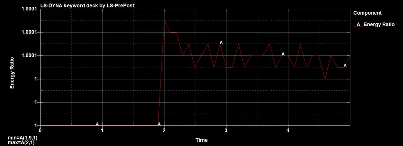
From the above plot, we can see that the energy ratio is almost equal to one and dictates that there is very little variation in energy of the system and hence energy is conserved with negligible variations. (Energy ratio is equal to total energy divided by internal energy + (kinetic energy/external work)).
Stress contour:
We will see the stress contour for 1 ms after hitting which is most critical time and mobile experience most of the stress.

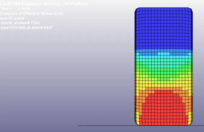
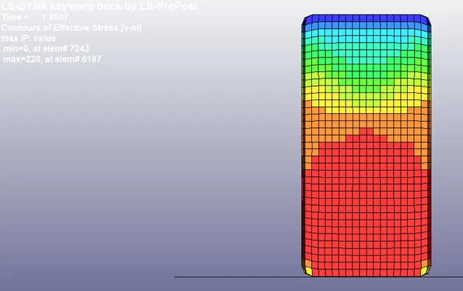
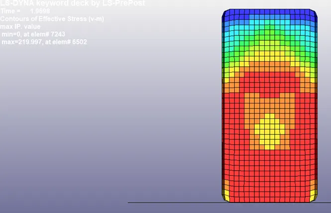
From the observation of the above contour, we can evaluate that the stress value is increasing from 170 MPa (at the time of hitting, refer to figure 1). Then, stresses rapidly moved ahead affecting more parts as the force continues to grow up to 1.95ms (maximum stress is 220 Mpa). As we know the yield strength of the steel (mobile mat) is 220 MPa which means the mobile part has gone under yield at 10 mm/ms velocity. After 1.96ms the stresses acting on the mobile started to drop and bounced back.
Learning Outcomes:
- To perform a drop test
- Understanding the importance of the unit system in Ls-Dyna
- The vulnerability of impact force
Conclusion:
The stress has increased suddenly within 0.02ms seconds with the sharp increase in stress. Thus, in order to improve the impact strength and to prevent the yield of the mobile either some damping is required or need to change the material properties.