Week 12 - Project-1
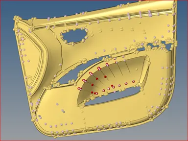
Aim: Perform the proper meshing of the component (Door panel) while fulfilling the given quality criteria and assign corresponding thickness to each part.
|
S.N |
Quality Criteria |
Value |
|
1 |
Aspect Ratio |
5 |
|
2 |
Skewness |
45 |
|
3 |
Warping |
15 |
|
4 |
Taper |
0.5 |
|
5 |
Min. Length |
2mm |
|
6 |
Max. Length |
6mm |
|
7 |
Min angle Quad |
45 |
|
8 |
Max angle Quad |
135 |
|
9 |
Min angle Tria |
20 |
|
10 |
Max angle Tria |
120 |
|
10 |
Tria % |
10 |
Introduction:
Modeling and meshing of the component is the first step toward the simulation. It is very important to get the best mesh flow and pattern to get the accurate result but again it depends upon the types of simulation and their requirements. In this case, we have a door panel meshing for a car crash. It has lots of features and ribs. So, here we are going to see how to mesh and get a proper FEA model.
Procedure:
- Geometry checkup and cleanup
- Mid-surface extraction
- Topology checkup
- Meshing
- Assigning thickness
So, let start with a detailed description of the method.
- Geometry checkup and cleanup:
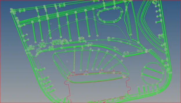
Fig. 1: Topology of the Door
From the above picture, it is clear that the topology of the door proper except at the lower part of the door. The "Red" line represents the free edge of the body which means it is not a closed volume. But we don't need to worry about this because the thickness of the whole component is less than 5mm. Hence, we need to perform a 2D mesh. It is always good to extract mid-surface from the parent body and perform geometry cleanup. However, sometimes extracting mid-surface without proper geometry cleanup of the parent body gives a distorted surface.
Now, let dive into mid-surfacing of the Door.
- Mid-surfacing:
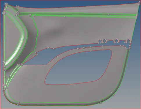
Fig.2: Mid-surface extracted for the base part (without any rib) offset by 2.8/2 mm (midsurface> skin offset)
If you can see this part is large in dimension and have a uniform thickness. All the features and ribs are made over this part. So, this part act as a base part. This mid-surface will be modified a bit to make some assumptions like removing some feature line (closest), filling the empty region at some required region.
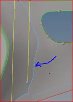
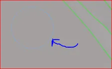
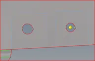
Fig.3: Disfeaturing the line feature for proper modeling as they are petty (quick edit> toggle)
The next step is to extract the mid-surface of the feature and ribs of the Door which has corresponding thickness. As the feature and rib pattern is not complex in this case. It is easily extracted and projected over the surface.
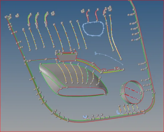
Fig.2: Feature and Ribs of the Door extracted using (surface edit> offset)

After extracting the mid-surface, ribs and features are extended to make a connection with the base part of the Door. Finally, the component is prepared for the meshing, and for that, we need to remove all the closest feature lines, excess feature line, sharp corner, and feature causing element failure (modified, if sensual).
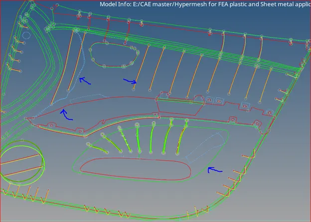
Fig.3: Topology of Door Mid-surface (Red: free edge, Green: 2 surfaces connected, yellow: 3 surface intersection, Blue: Suppressed line)
- Meshing:
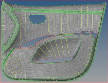
Fig. 4: Mesh of the Base part
Mesh in itself is the very challenging task of FEA WORLD. One has to gain proper control over the tool and understanding of the tool. It also requires experience to mesh quickly and properly in a complex region. Here, I will discuss some of the complexity during mesh with examples.
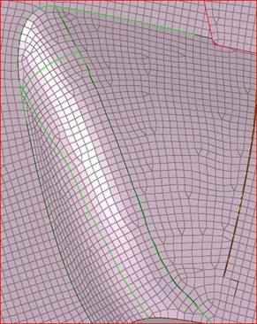
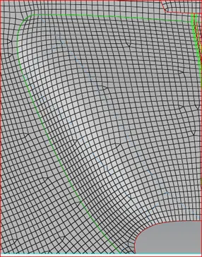
Fig. 5: Mesh before and after removing the feature line at the curved region
It is clear that the number of trias in this region was prompted due to the bend feature line but the number of trias is reduced to a minimum after removing the feature line from that region.
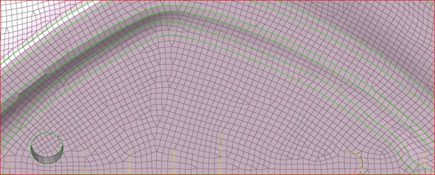
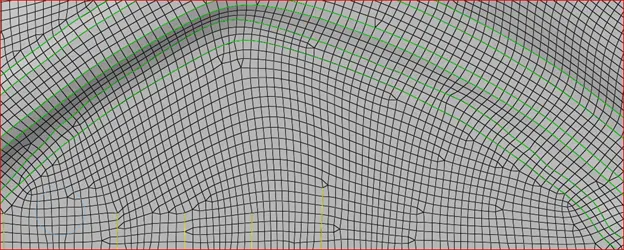
Fig.6: Performing the Hit-Trial method to get better mesh from the previous one (Before and after). Mitigating trias accumulating at the center.
In the above challenge, I often strive to get better mesh in the desired manner. In the above figure of Fig. 6, you can see, trias is segregating at the center of the mesh which is bad. So, to remove that I had to select the mesh properly and remesh it with flow alignment and size ticked during mesh.

In this panel, the flow option is really helpful to obtain the better mesh flow in the desired direction at the meantime mesh selection must be controlled.
- Assigning thickness:
The component of each part and subpart must be assigned with proper thickness. It helps compare the approximate FEA model with the original component. It is also essential during the simulation for example during contact simulation, crash simulation, and others.
Learning outcomes:
- It is good to make trade-off while meshing the component
- Mid-surface must be extracted properly and joined
- To gain good mesh flow you have to make a strategy about how to remesh
Conclusion:
After creating surface mesh one have to remesh to gain the required mesh flow and pattern and proper study of the component is good before the commencement of modeling.