Assignment 7-Side Pole Crash Simulation Challenge
A side impact of the Car with the rigid pole at an angle
Introduction:
Assume that you tried to steer your car at high speed at turning but speed was enough to outwit the Tires resisting force and you hit the rigid cylindrical object like a tree. So, in this and many other cases like a side car accident, slipping on a snowflake, etc. can cause damage to the passenger if the car is not designed with great care. This is where the side-impact standard comes into the role. The standard has been devised by the standard maker like FMVSS (214, 201), EURO NCAP, US NCAP, and IIHS. Again, in this paper, the car with the simplified model is taken for the analysis purpose. The model is prepared following the guidelines suggested by the FMVSS 214 standard. The analysis is executed to check the intrusion made inside the car, intrusion inside the fuel tank (for hybrid electric vehicles, battery-package system, which is more dangerous), and how much the B pillar is affected.
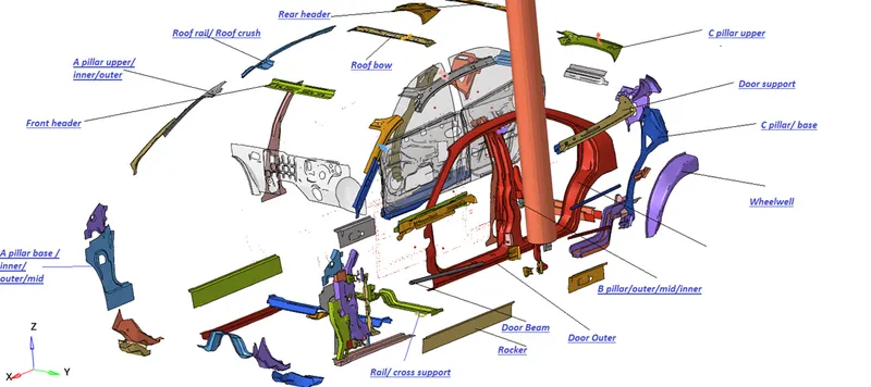
According to the standard, relative displacement (intrusion) must be small before the inflation of the airbag. Indeed, the strength of the B pillar and other surrounding structures should be high enough to bear the impact force and should not deform at least up to a small duration of time. The major component which is going to play the major role in this impact is B pillar, rocker, Door outer, Door beam, Door support, roof rail, roof bow, front header, and cross rail. So, let's our discussion starting from the preparation of the model, simulation to the analysis of the result and validation.
Modeling and setting up:
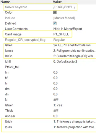
The meshing of the model is done using the Shell element and rarely brick element (lock mechanism). The connection of the spare part is created for FEA representation. The connection is made using the RBE2 (two nodes) and spring element. The shell property used is reduced integrated QEPH formulation (one integration point only) and considered full geometric nonlinearities with possible small strain formulation. The thickness changes are taken into account and calculated using the iterative projection method. The solid element property is of 8 nodded Belytschko with reduced one integration and consider full geometric nonlinearities with small strain formulation. Typically, when there is large rotation, using the co-rotational frame for the element co-ordinate system is more accurate but in this case, the solid element used is of very small part only using a non-co-rotational frame is also accurate.

The material used is of two types' i.e. elastic material (LAW1) and isotropic elastoplastic material (LAW2). Elastic material does not need lots of parameters for proper definition but elastoplastic materials do. So, elastoplastic material will consider the plastic strain effect and also consider the strain rate effect. However, in this case, the value of c is set to 0, and the strain rate effect is negated. The material elastic modulus is not specific but is used between 200 to 210 GPa.
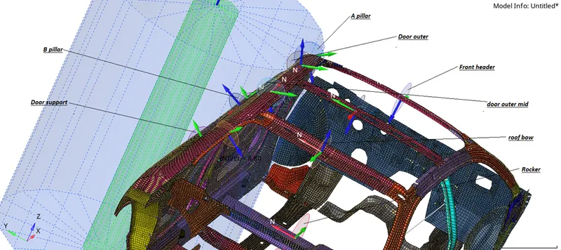
The interface is the important parameter to set to perform this explicit analysis. This help one component to interact with another component in a various way depending on the types of interfaces used. In this case, the Type 7 interface is applied over the whole body to let them know their parts interacting with each other. Another is the rigid wall (cylindrical wall) which is provided with the search distance. This search distance helps in searching the slave node entering inside that volume as shown below:
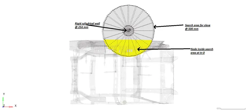
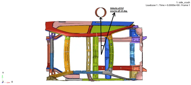
The distance between the rigid wall and car is around 150-200 mm. During the simulation, distance does not have an impact on simulation but one must keep the constant velocity while hitting the wall. It is easy to do with the in computer. The velocity of the car is given at an angle of 15 to the horizontal to hit the pole according to FMVSS 214 standard. The magnitude of inclined velocity is 8.8 mm/ms (32 mi/hrs.). The Skew is created to define the velocity at 15 degrees which are depicted below (not skew):
Since we have done all the setup for simulation. It is necessary to get the simulation result at the main location. To get that data from the various part we have to create a section. In this, the section is created at various main locations to get the force data at each time.
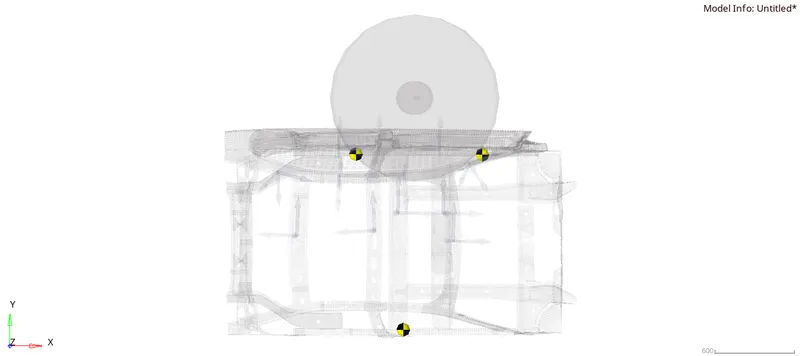
All those things we have discussed for now was for the car. To analyze the effect of car impact on the human body, we need acceleration data. Acceleration tells us how quickly the car velocity decreases and if there are any fluctuations. From this data, we can predict the inertia of the human body too and injury prompted. The accelerometer is created at three locations as shown:
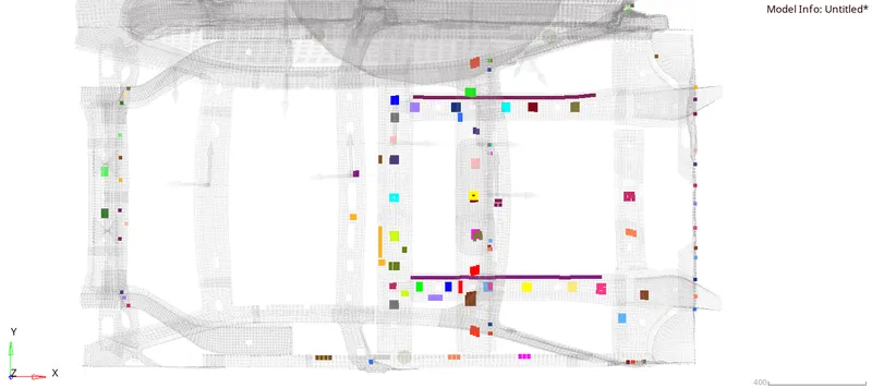
Finally, the mass of this truncated model is increase by adding lumped mass at these given locations to reach 700 kg in total. The added mass is shown below with different hard colors.
Before performing the analysis it is recommended to perform penetration and intersection check to avoid any kind of instability that occurs at the start. Despite that inacti when set to value 6 then initial penetration will be removed partially to avoid instability.
Analysis:
- Total Energy:
Let's check how accurate the simulation result is with the given input. To perform that analysis, we have to see if the total energy is constant or not. The plot given below will give you a glimpse of energy exchange at the different time frames.
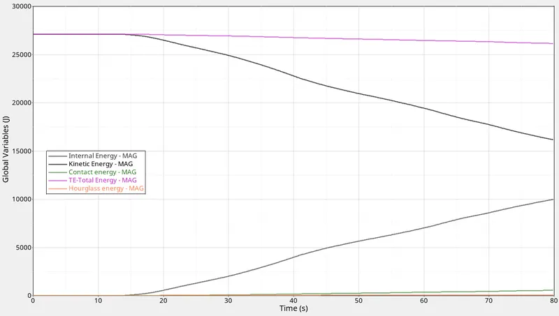
The magnitude of the internal energy of the system is increasing at the cost of dissipation of the kinetic energy. The quantity of total energy is varied in a very insignificant amount due to loss of energy in contact. Hourglass formation is almost negligible comparatively. So, we can say that the simulation result is good from the perspective of energy and input have given to the model.
- Time step:
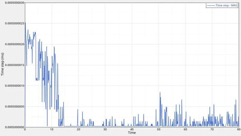
The variation of the time step is very frequent and sharp. This variation is happening at the Nanoscale level. Thus, the variation is very small and is acceptable and can be assumed constant. As there is no substantial variation in the time step, no mass scaling is done (very insignificant).
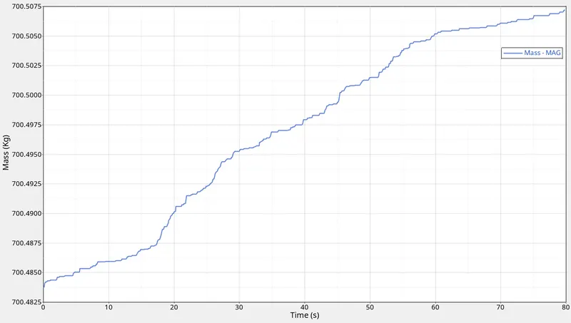
From the above plot, the mass scaling quantity is only 75 g. Thus, we can say that mass of our model is stable and not varying with time and is acceptable.
Sectional force on Cross-member:
Cross-members are very crucial in the side-impact analysis as these components prevent the body to shrink or deform inward. When the car hits the rigid body maximum amount of forces will pass through the cross member of the base and roof. This component along with door bar and support, door outer, B pillar, and rocker are also involved in the majority to prevent deforming. But the forces acting on every other component eventually pass from the cross member. So, let's see the number of forces acted on the cross member and any variations:
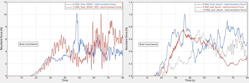
From the above plot, we can imply that the force acting on the base cross beam is higher than the force acting on the roof cross beam. Thus, the cross beam at the base is resisting more force. The highest peak of the forces on the base cross beam is between 45th and 75th second.
Peak velocity near the Door:
Studying the velocity near the door gives us an idea of "What acceleration the passenger will face?" So, to know the velocity near the car then let's point out one node with id 337773 and examine the velocity variations.
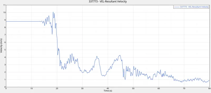
The velocity of the node is almost constant before hitting the rigid cylindrical wall (up to 12 seconds). Then, the velocity started to fluctuate after hitting the wall. After the 20th second, velocity dropped drastically as shown in the plot. This node is very close to the hitting rigid wall so the velocity of the node dropped below the 1 m/s and almost 0 m/s. From the velocity diagram, we saw that there is no jerk near the door. But let's explore a bit on the rear side of the vehicles. The acceleration of the 3 places (as shown in modeling and setup) is given, one at the front door rocker arm, one at the rear door rocker arm and another is at the rocker arm of the opposite side.
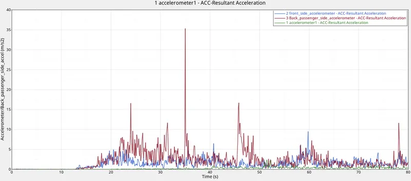
From here we can see that acceleration of the rear part of the car very high. At 35th seconds, the acceleration has increased suddenly like a jerk which is almost 35m/s2. This is high enough to injure anyone sitting on the back side of the car.
Intrusion inside the car at B pillar, hinge pillar, and fuel tank:
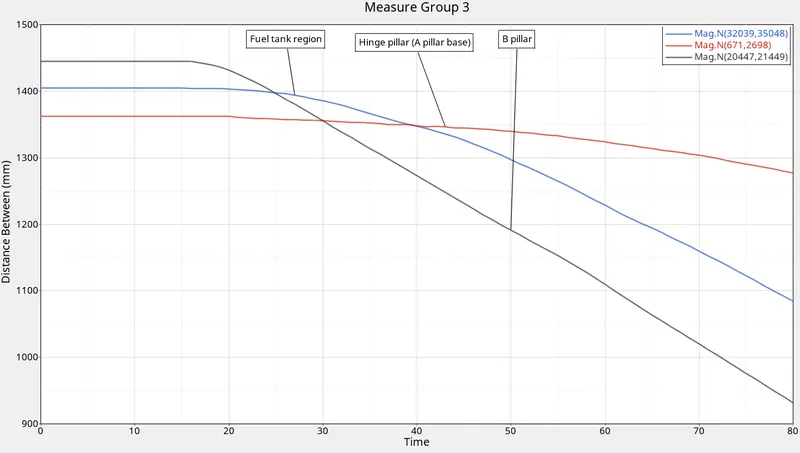
The intrusion or deformation of the component can harm the occupants and the inner part of the car like a fuel tank. From the above plot, it is obvious that intrusion near the fuel tank is 320mm and near the B pillar is 530 mm which are substantial. This intrusion must be avoided by some alternative structure or changing the material of the car part near the fuel tank and b pillar region. So, let's discuss some suggestions made after examination of the alternatives.
Alternatives:
The alternative use for reducing the intrusion near the fuel tank region is the additional crossbeam. The crossbeam is situated between the base C pillar as shown below:
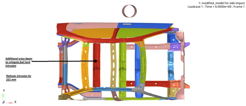
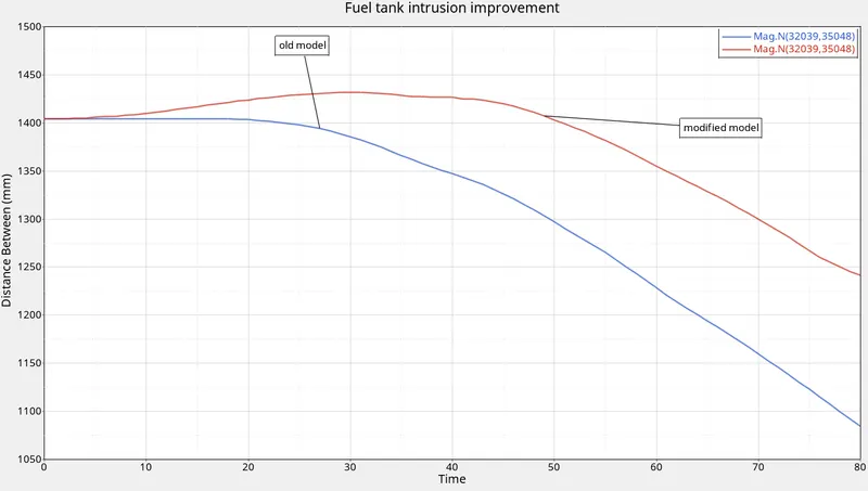
The cross beam seems to reduce the fuel tank intrusion by 160 mm which is significant. The problem might be a material cost which will increase and space for other auxiliary including fuel tank will be difficult. For possibility purposes, it shows that fuel tank intrusion can be reduced to some extent to protect fuel tanks. The difference is shown in the plot below:
Errors and debugging:
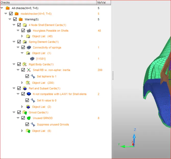
There is no error in the model however some warnings are there. Some of the warnings are due to the unused sets and node group which is deleted. Rigid body inertia is set to spherical so that inertial will be equal in all directions. Spring connectivity issue was due to free node and is deleted. Most of the warning was due to truncation of the model.
Some of the results of the animation:
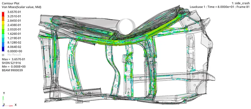
Von misses stress occurring on the body mostly on A-pillar and B pillar
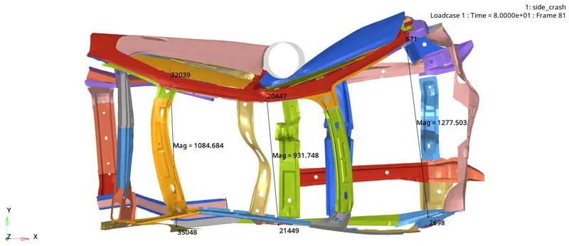
Intrusion measurement at the fuel tank, b pillar, and hinge pillar
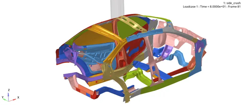
Deformation of the body at 80th second (base cross beam is deformed)
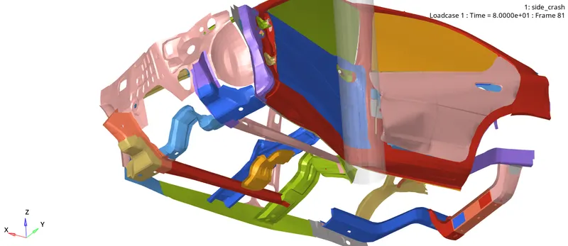
B pillar is pushed inward at a greater extent
Learning Outcomes:
- significance of B pillar, rocker, and cross arm in side-impact
- Base cross beam face a large amount of force compared to the upper cross beam
- The fuel tank region can be under threat due to maximum intrusion during the side impact
- FMVSS standard for side impact
Conclusion:
During side impact, the cross beam has a significant role in resisting the deformation of the body laterally. So the body must be provided with an optimal number of the cross beam with good strength to avoid intrusion.