Assignment 6-Frontal Crash Simulation Challenge
Frontal Crash simulation of simplified CAR model of Neon with a thorough analysis.
Introduction:
Frontal crash analysis of the vehicle system is of prime importance for the car manufacturer to keep their customer safe. This analysis is divided into two parts i.e. crashworthiness and occupant protection. So, crashworthiness includes the vehicle's frontal part capacity to absorb energy during the crash and distributing force. Occupant protection deals with the occupant restraint system and safety.
All safety standards are made based on occupant protection. And car manufacturers are suggested to design a car in a way that maximum occupant safety will be gained. Some of the standards are FMVSS (Legal requirements based), US NCAP (Consumer rating), IIHS (Insurance Institute for highway safety).
Crashworthiness of the simplified model:
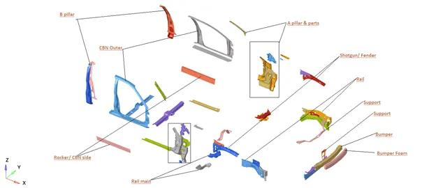
This paper is all about the crashworthiness study of the simplified car model. We will perform a study overt the main component of the car like a bumper, support, rail, fender, A-pillar, B pillar, and Rocker. These parts are under maximum stress and maximum force passes through them. There are two ways to transfer maximum force from the bumper to the rest of the car. This path creates a diversion to prevent intrusion near the instrument panel so that occupant will not face any intense injury.
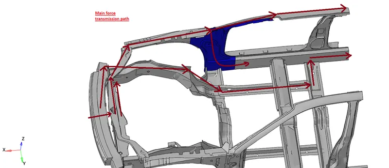
Here, you can see the two main paths.
- Bumper foam> Bumper> rail 1> rail 2> rail 3
- Bumper foam> Support 1> Support 2> Fender> A pillar> CBN outer and rocker
Studying these two paths will give us a lucid idea of how the body is going to act during a crash and the effectiveness of the energy absorption. In this model, the fender is directly connected with the rail, so at the very first time of impact, all the forces will be passing through the rail down to the car floor and chassis region. After some time the bumper will hit the support, then the force will be distributed in two paths i.e. rail and fender both. Eventually, the front part of the car will go under a maximum crush. At crushing time we have to focus on intrusion inside the car near the passenger.
Modeling of the car body:
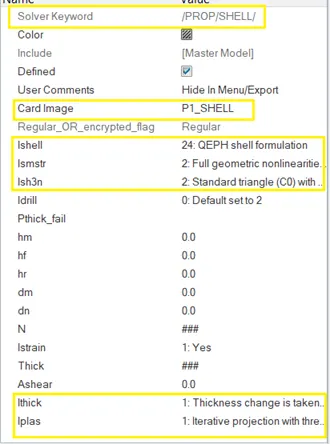
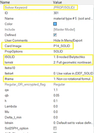
The car is modeled using the SHELL (quad and trias) and Brick element. The component of the car is connected using the SPRING and RBODY 1D element. The initial velocity is subjected to the whole body according to FMVSS standard i.e. 15.64 mm/ms. This velocity is kept constant, as suggested by FMVSS, before hitting the rigid wall. The property of the shell and brick is shown below. The shell element has reduced integration but physical stabilization for hourglass and nonlinearities is taken into account. The shell element will also consider the change in thickness under load and a more accurate method is used to calculate thickness change (Iplas). The solid element is also reduced form while including geometric nonlinearities with a non-co-rotational element coordinate system.
The interface used in this case is Type 7. This interface is applied to the front part of the car body which is going to crush and prompt self-impact. The rigid wall is created with a search distance of 1000mm. This method helps in reducing the computation time because the only body entering in that region will be considered as a slave for the rigid wall and unnecessary calculation will be prevented. To perform a study over some component with time, the section is created over that component.
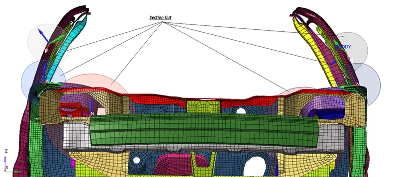
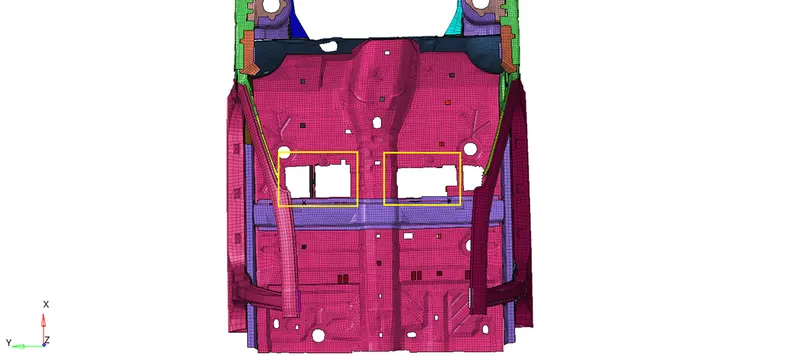
The accelerometer is attached below the B pillar with the rocker because the rocker does not deform and gives an acceleration of the car body for proper analysis. We have mentioned that the car model used is the simplified form of the actual car. To resemble the result, lumped mass is required to add to the car body to match the 700kg mass. The mass is added as shown below:
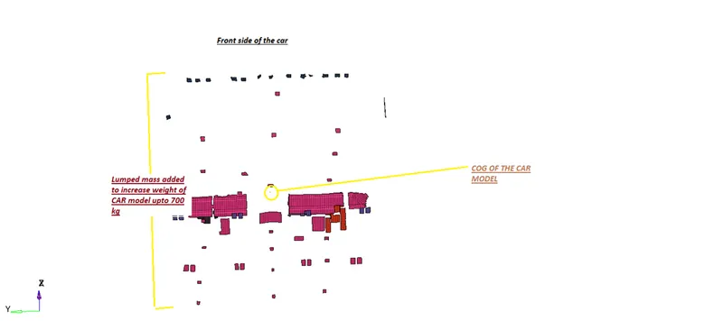
Below you can compare the position of the lumped mass compare to the car body.
Analysis:
The paper is all about crashworthiness so we will focus merely on how the frontal part is behaving despite the structural strength and stresses occurring on the component. Let's start our discussion by checking the conservation of energy from the plot and then moving ahead.
- Energy plot:
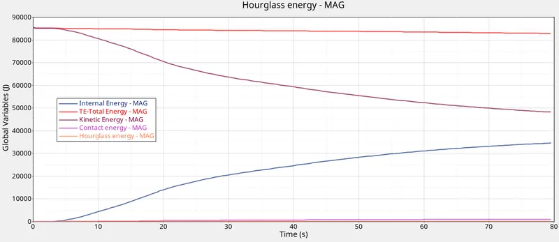
The hourglass energy is almost 0 and contact energy is present but in a very small amount. The kinetic energy is decreasing at a proportional rate with increasing internal energy. The reason the complete kinetic energy is not converted into the internal energy is that the system is not stable after hitting and motion continued. But in the Full car model, you will see that almost all kinetic energy will be converted into internal energy during the crash period and the car come into the rest. The total energy is conserved while some of the energy is lost to the contact energy.
If we check the kinetic energy of the car, initially, where the mass is 699.75 kg and the initial velocity of the car is 15.64 m/s. Then the kinetic energy of the car becomes equal to 85, 582.7 J where the kinetic energy in simulation at t= 0 is 85, 352.69 J.
- Time step:
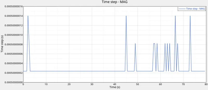
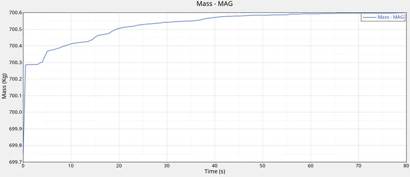
There are some peaks in the time step and mostly for a very short duration which is again handled by mass scaling. Below you can see the mass scaling is also negligible. It's like 1 kg of extra mass is added to the system during simulation to maintain the time step.
- Acceleration of Rocker:
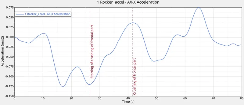
The acceleration curve here depicting the crushing behavior. The time between the 12th and 25th second the acceleration has decreased due to the car fender and rail. Then after, the time between 22nd and 42nd the acceleration of the car increases meanwhile the frontal part of the car was crushing. Though we know that the acceleration of the car had to decrease significantly at the last time which is not the case because of the model we have.
- Rail sectional force:
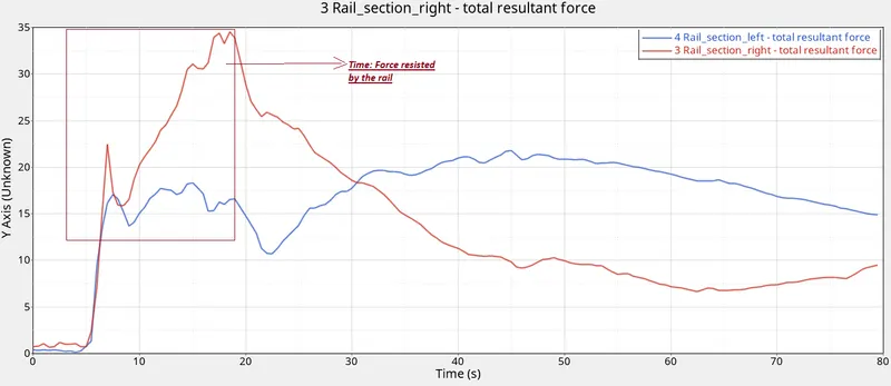
The sectional force acting on the rail has increased dramatically at 6th second. This is the time the car hit the rigid wall while crushing the bumper. The other observation is the force acting on the right rail is higher than on the left rail. Before the 20th second, the force is resisted by the rail. After the 30th second, force gradually started to decrease on the right rail but it increases on the left rail.
- Fender sectional Force:
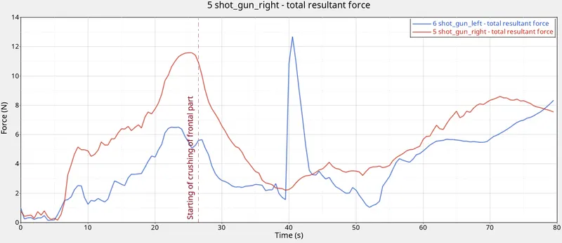
The force from the bumper passes lately to the fender through the support and then the fender itself hit the rigid wall. So, the force is resisted by the fender for up to 25th seconds then it undergoes deformation (crushing). Lastly, the force on the fender is large because the fender is suppressed against the wall in a crushed state.
- A pillar:
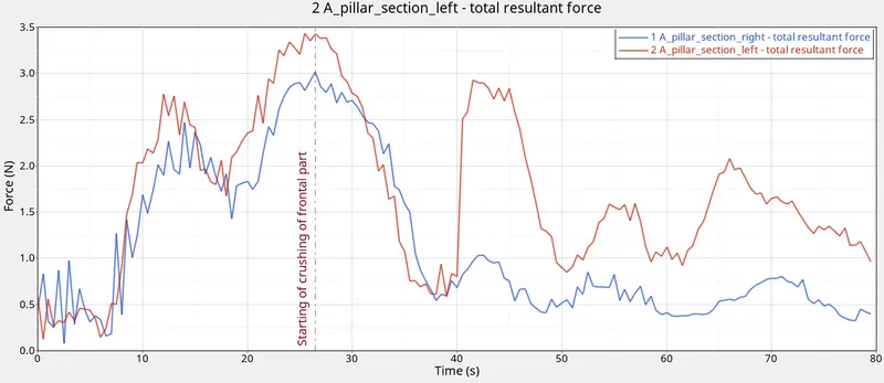
During frontal crashes, our main focus is always on intrusion and A-pillar. This is achieved by well crushing behavior. Here, you can see the pattern which is resembling with the force acting on the rail and fender. The force is more at the A-pillar when the force is resisted by the rail and fender. But the force on A-pillar is less when the frontal part starts to crush and absorb all the energy (after 25th seconds).
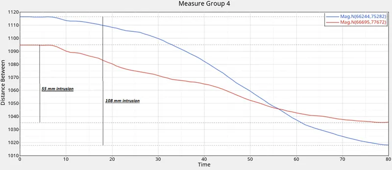
- The intrusion at front of the interior:
Let's see some of the main pictures of the frontal crash:
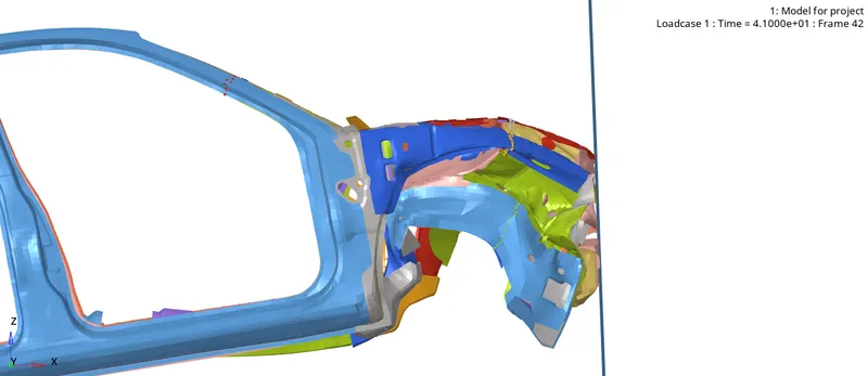
The bumper is pushed down due to the force and crushed the rail
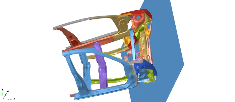
The bumper of the car is forced inside which is unlikely in full car model
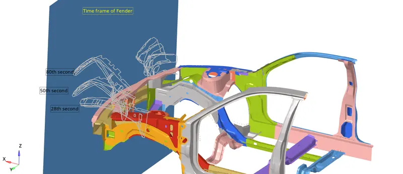
The time frame of the fender (Left fender is not deformed largely compared to right fender)
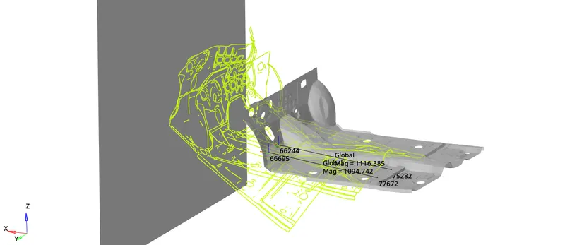
Car floor panel is twisted and intrusion is substantial at the dash region (see the plot in intrusion part)
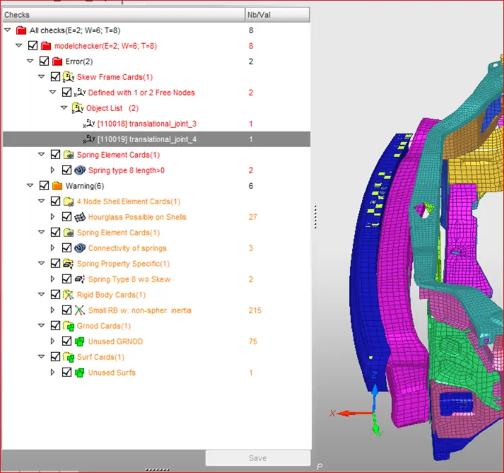
So from the above error, skew frame card error is removed by deleting the skew as the skew origin was defined by free node as shown below:
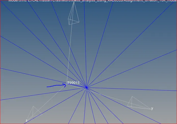
All these warnings and error has occurred due to the truncation of the full car model. Some of the warnings like connectivity of the spring, unused node group, sets, surface card, etc. are the warning which is deleted because these pats have no role in this simulations. Another error like the inertia of the rigid body is not set to spherical. If you set the inertia of a rigid body to spherical, the inertia will be equal in all directions.
Learning Outcomes:
- How to model the car for frontal crash
- How to debug the error and warnings while modeling the front crash simulation
- Main components involved in crash simulation
- Significant of rail and force diversion and crushing behavior of the frontal part
Conclusion:
It is of utmost importance to absorb the energy induced during a crash while crushing the frontal part. It is also important that the car should come to rest sooner and prevent further intrusion of the frontal component inside the car near the passenger. Rail and fender should be designed in a way that it should not force the bumper in a downward way.