Week 5
Aim: To Check the geometrical errors in the model and mesh it with tetra element with no kinks and dips on the surface of the model using given quality criteria.
Target length: 1
Minimum length: 0.5
Maximum length: 2
Tet collapse: 0.2
Steps Involved:
- Geometry Clean-up
- Assigning quality criteria & perimeter and macros length
- Surface Meshing
- Defining Volume body
- Volume Meshing
Geometry Cleanup:
Generally, when importing the file from CAD software there is always some stimulated geometrical error to appear. Primarily, giving topo from (topo>faces>topo) single cons error is eliminated. Then after, checked the error in Check> Geometry> Execute. This assigned no error in the model. Cleaned model is shown below:
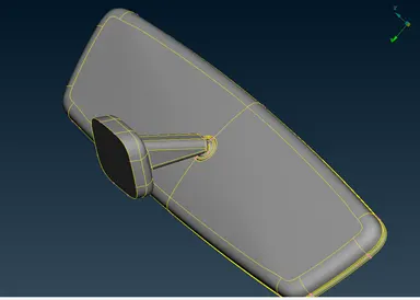
Figure 1
After cleaning the model, the distance between the features lines was measured to ensure that they are passing the minimum length criteria. In a place where minimum length criteria were failing was subjected to disfeature. This model was readily passing the criteria and very little disfeaturing was necessary which is shown in Figure 2.
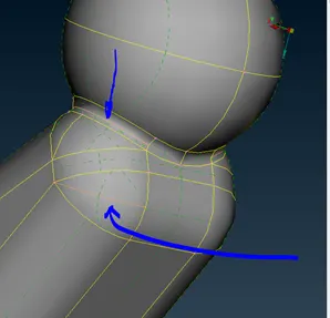
Figure 2
Assigning quality criteria & Perimeter and Macros Length:
Quality criteria need to be assigned before the meshing for good practice. It helps in the proper growth of the tetra elements being circumscribed with given criteria. So the data is filled according to given quality criteria in Mesh parameter and Quality parameter (Shell and solid meshing). Shell meshing criteria are mentioned for surface meshing whereas solid meshing criteria are mentioned for Volume meshing (3D elements).
Surface Meshing (2D meshing):
This is the first step to achieve the Volume mesh. Hence, Volume mesh is totally dependent over the quality of surface meshing. Surface meshing is done on the surface of the component.
The best practice that has been used since is Ortho trias and Trias from Spot Welding. However, map meshing algorithm is also most suitably used to obtain Ortho trias and Trias. The only difference between Spot meshing and Map meshing is that the former is used when there is bend, weld and extra spots in the macros area and later are used when one wants to align the elements with the quadrilateral shaped macros area or close to it. Indeed, Spot welding is used on the surface in this model.
This model has 4 components and they are depicted below with surface meshing (Ortho Trias at the bent and Trias at the plane surface):
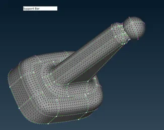
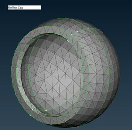
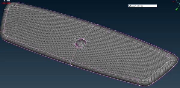
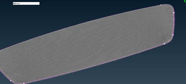
All those 4 components were thoroughly probed to see if there is any kinks and dips on the surface of the components. No kinks and dips were found. In addition, you can see the figure MIRROR (delineated on the top-left). Though the surface is plain, trias mesh generated was coarser that’s the reason I opted Ortho Trias and obtained better results as shown.
Defining Volume Body:
There are 4 parts in this model so four-volume need to be defined from the Volume mesh> Volume> define> Manual. After selecting the body the volume list is generated. Now, that’s a particular part that is ready to mesh ahead. Similarly, every part is defined.
Volume Meshing:
Volume meshing emerges from surface meshing and terminates in the cavity with tetra and Hexa mesh by filling the cavity. Quality of volume mesh is dependent on the surface mesh so surface mesh must be of fine quality to reduce failure like Tet-collapse.
There is two mesh type in this area which is structured and unstructured mesh. The structured mesh is also categorized in many forms. We will be using Tetra FEM (Growth factor is lower) which is mostly preferred for structural components because these components are thinner and of uniform length. In contrast, Tetra Rapid is used for larger volume domains like CFD or structural components with thick volume.
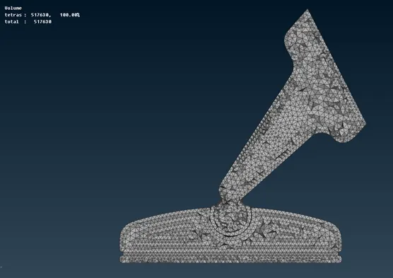
After proceeding with the volume mesh generation, the obtained mesh is free of Tet-collapse. Again, Kinks and dips were perused and found no such defects. The volume mesh is depicted below halved in symmetrical form.
Learning Outcomes:
- The difference between Tetra Rapid meshing and Tetra FEM
Conclusion:
THE Tetra FEM algorithm is best for structural components having smaller thickness and volume domains. And, one must make surface meshing of better quality for better volume meshing and check if there are kinks and dips and collapse failure in volume mesh.