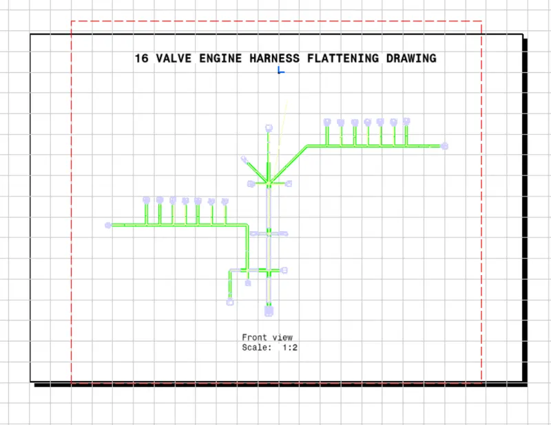
Wiring Harness Routing of 16 Valve Engine
Wiring Harness Routing of 16-Valve Engine
In this challenge, we will perform the Wiring Harness Routing of a 16 Valve Engine and at the end will prepare a flattened view drawing for the same. All packaging rules & the best industry practices will be followed during this process.
The steps that need to be followed for executing this task are as follows:
- Identifying the electrical components in the engine
- Defining the mechanical components electrically & saving them in the catalogue
- Setting up the assembly by placing the required connectors, clips, clamps, etc
- Proper routing of the bundle without any interference
- Preparation of flattening file & 2D drawing creation
"A problem well defined is a problem half solved". To start proceeding with any task an engineer must understand the given problem/challenge first. Without realizing the purpose there will be a high chance of making a lot of mistakes during the process hence let's start the challenge by first identifying what is our input & what output is required.
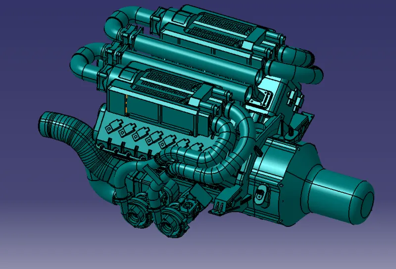
The given model is a 16-valve engine that has some electrical components attached to it. These components will be connected through wires/bundles & this complete package is called an engine harness that will be connected to the vehicle harness. The electrical components of the engine are,
16 - Fuel Injectors
4 - Cam Shaft sensors
1 - Engine Coolant Temperature Sensor
2 - Engine Oil Temperature & Pressure Sensor
1- Neutral Position of the Transmission Sensor
1- Vehicle Speed Measurement Sensor
All these sensors require current/power to operate, thus by using the appropriate connectors we can route the wires to supply the power.
Each sensor may have a different number of terminals. Depending on the type of connector required we can download the CAD data from various websites (like Tyco) online.
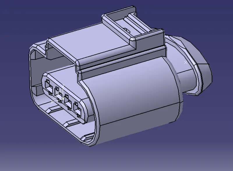
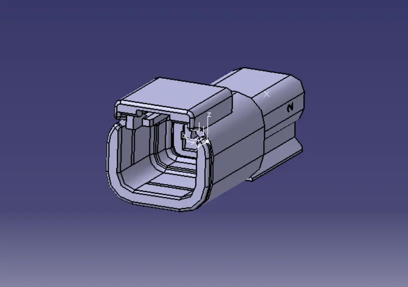
Using Electrical Part Workbench we can define these mechanical components electrically in order to route the bundle/wires.
Also, these connectors may also be helpful in the future for different projects hence saving these already-defined connectors as a catalogue will help the designers in the future.
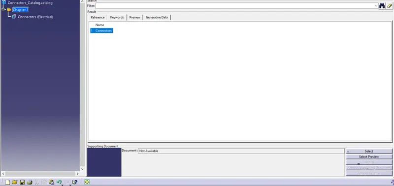
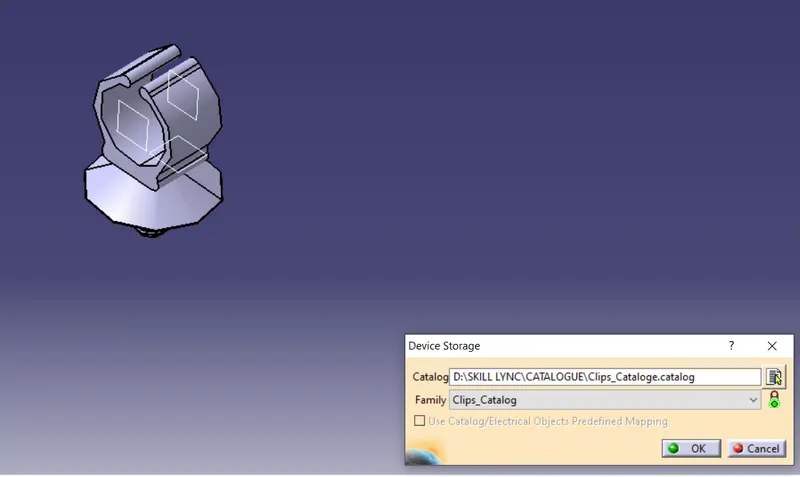
Now once all the components like connectors, clips, clamps, channels, etc are defined, place them on the engine accordingly.
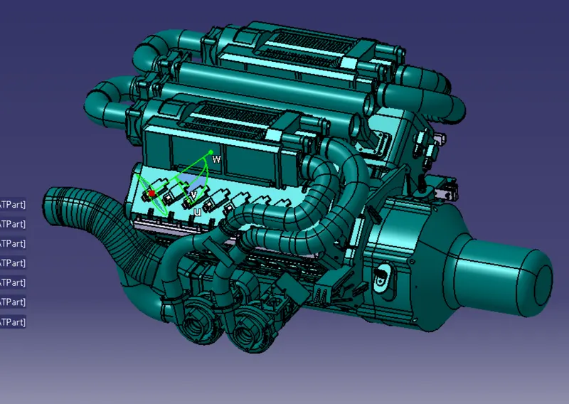
A design engineer needs to define how & where these components need to be placed by considering the environmental factors & feasibility of the routing in real-time conditions.
An interconnection connector is also used in order to connect the engine harness with the main vehicle harness hence the placement of this connector must be appropriate to have easy access to the service.
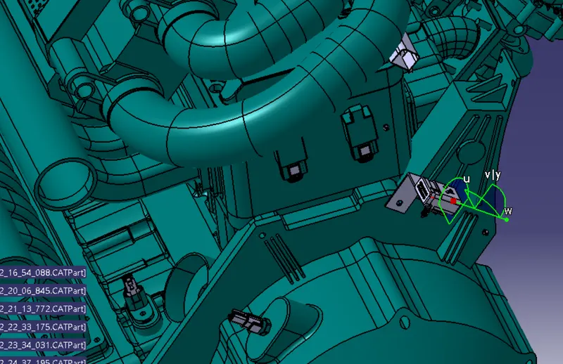
Clips & Channels are used for guiding the wires to their desired location. The designer needs to make sure that the placement of these components should not affect the functionality of the system.
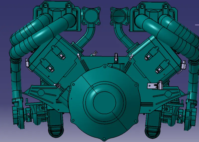
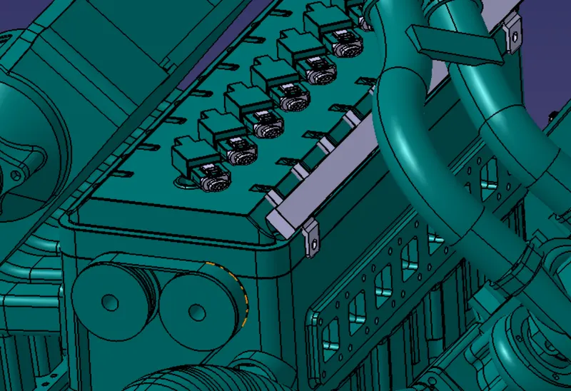
Once the assembly is set up, the routing of the bundle can be started. Appropriate wire diameters, bend radius & branching points are crucial to have a clear harness bundle.
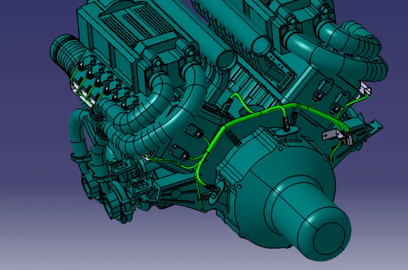
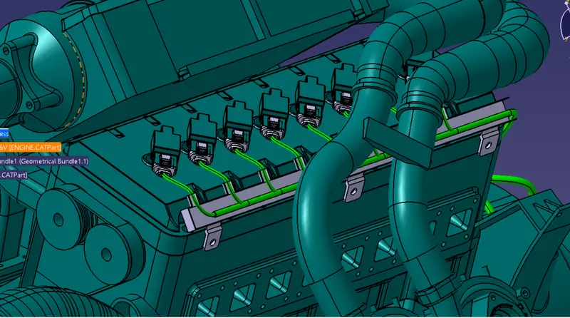
Also the protective covering can be applied in order to avoid any damages to the wire because of engine heat or any other environmental factors.
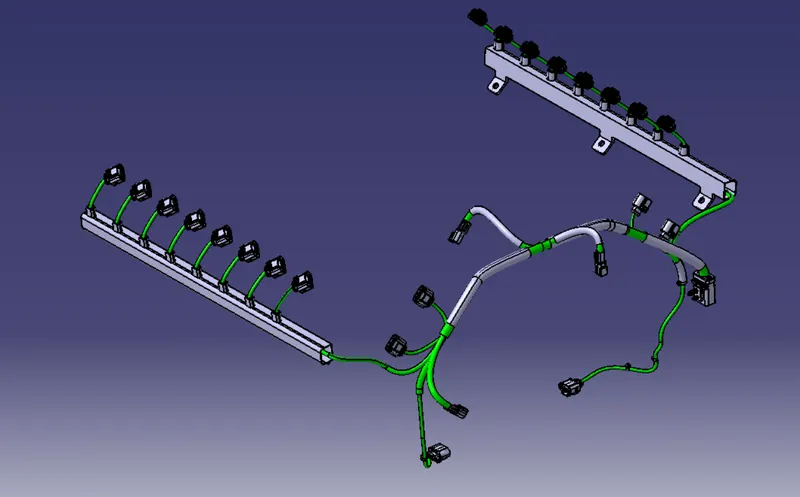
Using the Flattening workbench in CATIA V5 we can plot a 2D diagram for the harness assembly.