Pre-Processing of Door Inner Panel using HyperMesh
AIM:
To generate midsurface and perform geometry clean up on the given component and also generating the mesh with low tria concentration under the given quality parameters.
SOFTWARE:
Hyperworks 2020.
PROCEDURE:
First import the CAD model in HYPERWORKS.
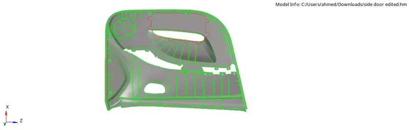
After importing the model, generate the Midsurface manually by using the 'offset' option under "Geom > surface edit > offset.

The given model has variable thickness thus the Midsurface for all the components should be extracted individually by measuring the thickness of every component.
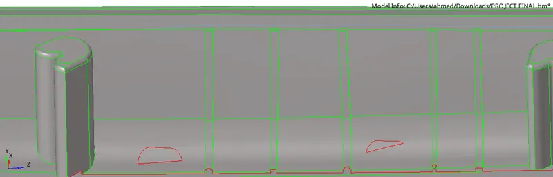

Few components in this model have uniform thickness such as the outer body (2.8mm) thus the Midsurface of this component can be extracted easily by giving an offset value of 1.4mm but for the components such as ribs are having variable thickness. So in order to extract the proper Midsurface of such components we need to use a different method.
In this method we first create a Midline of the rib. To create a Midline Go to "Geom > Lines > Midline and select the two lines between which we need to create a line.

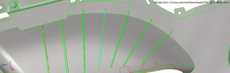
Now trim the surfaces which are parallel to the midline by using the "trim with lines" option under "surface edit".

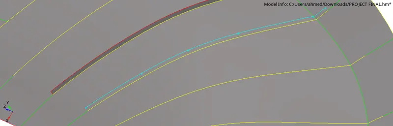
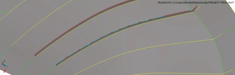
Then Go to "Geom > surfaces > ruled" and create a surface by selecting the trim line and the midline. This will give us a proper Mid Surface of the ribs which is having variable thickness
 .
.
Make sure to check whether the surfaces are connected to each other or not. If the surfaces are not connected then Go to "Geom > surface edit > extend option and select the line (edge) which we need to extend and then select the target surface and extend it.

Similarly we need to perform this operation for all the variable thickness components.
Always make sure to mention the thickness under the name of the component when the Midsurface is extracted for an easy recognition of the componentS.
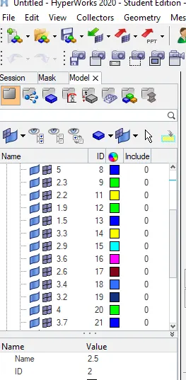
When all the midsurfaces are extracted start meshing the components under the given quality parameters.
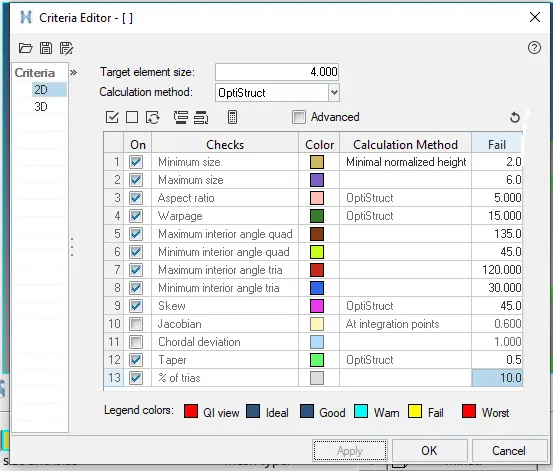
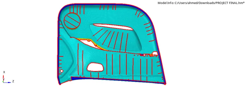
To perform meshing Go to "2D > automesh > surfaces and select the element size as '4mm', mesh type as 'mixed' and click on mesh. Mesh all the surfaces according to the given criterias.

Before meshing, always perform a geometry cleanup manually.
While meshing make sure to select all the surfaces which are forming a 'T' joint or surfaces which are perpendicular to each other. This will help in the mesh connectivity and also saves the time of a user.
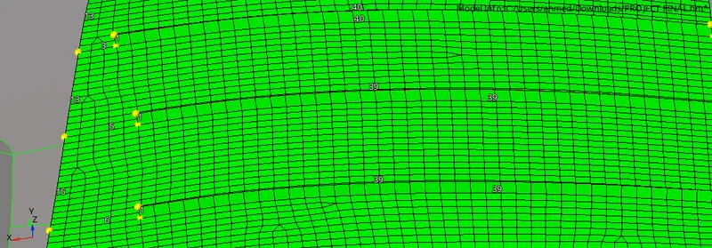
Once all the components are meshed within the given quality parameters, check for the edges. To check this Go to " Tool > edges > elems. Select all the displayed elements and click on find edges. If there are any edges which are disturbing the mesh connectivity then fix it by joining those elements.

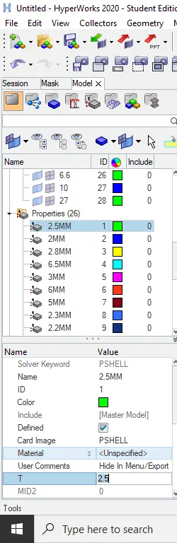
create properties for all the components and give the thickness to them respectively.
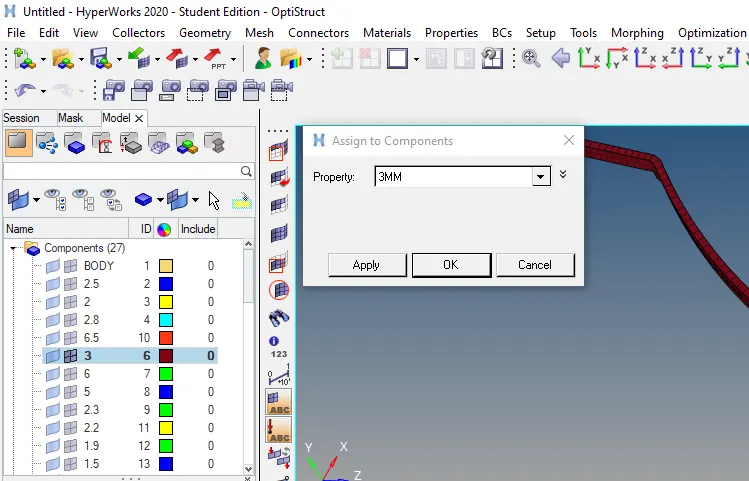
Now assign these properties to their respective components.
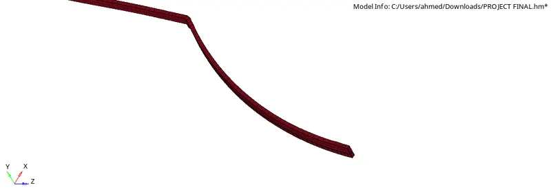
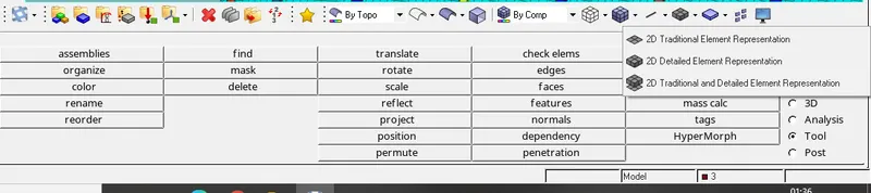
After all components are assigned with their respective properties, select "2D Detailed Element Representation".
Save the model.
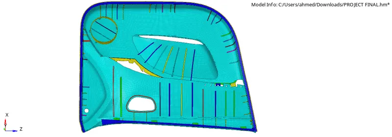
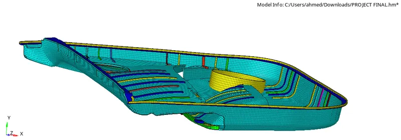
Final output:
Result:
The given component has been successfully meshed with a target element size of 4mm and cleared all the given quality criterias.