Steps to follow while performing 2D mesh in HyperMesh
Aim:
To generate midsurface and perform geometry clean up on the given components and also generating the mesh under the given quality parameters.
SOFTWARE:
Hyperworks 2020
USER PROFILE:
RADIOSS
PROCEDURE:
MODEL 1:
First, import the given HM model in HyperMesh.
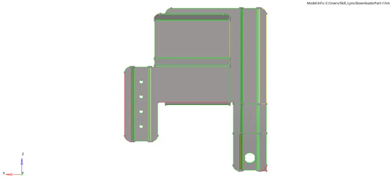
After importing the model perform geometry cleanup on the "Parent Geometry" manually.
The free edges in the geometry can be fixed by using the "Toggle edges" option. To perform this operation Go to "Geom > Quick edit > Toggle edges or Press 'F11'.
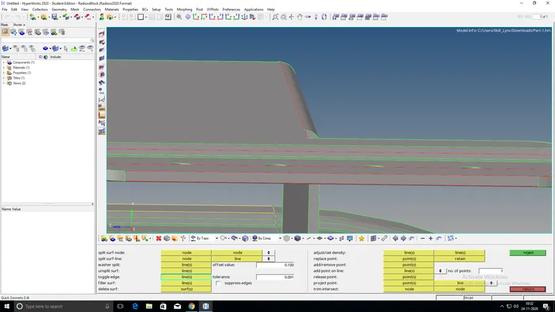
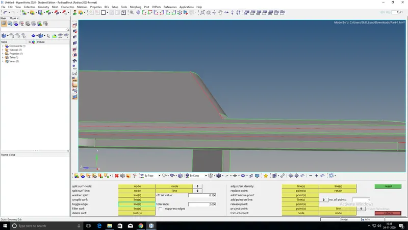
Create a surface where surfaces are missing by going to "Geom > surfaces > ruled" option.
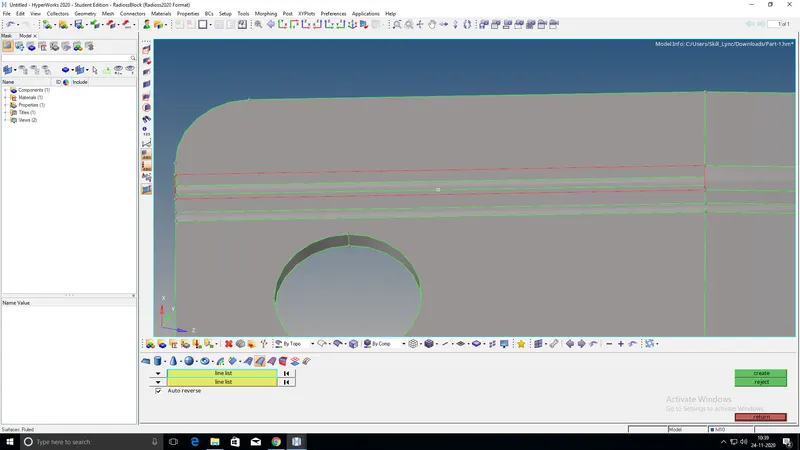
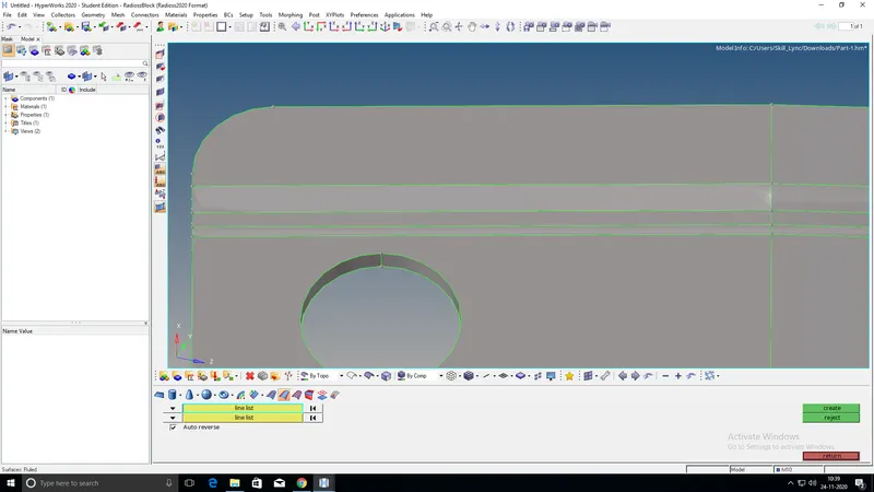
Once the geometry cleanup is completed on the parent geometry, extract the midsurface.
To extract mid surface Go to "Geom > midsurface > auto midsurface" and extract the surfaces by selecting all the displayed surfaces of the parent geometry.
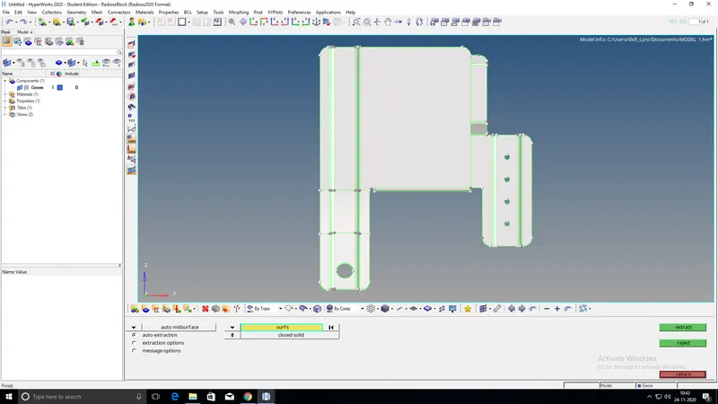
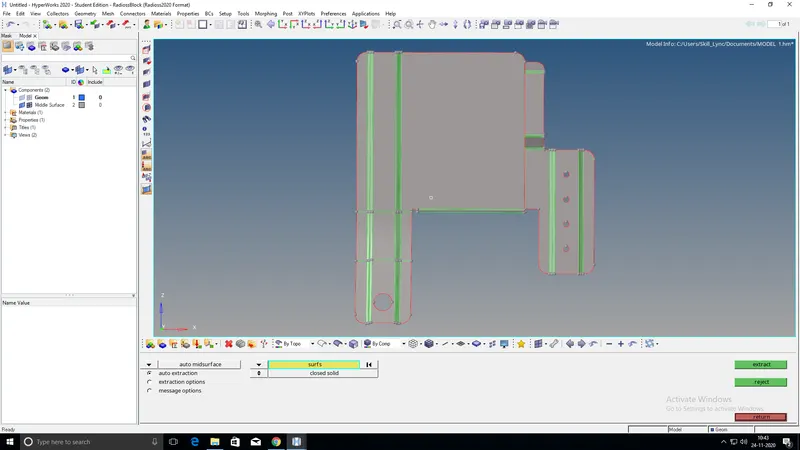
Once the midsurface is extracted perform geometry cleanup manually on the midsurface. This cleanup mainly involves, trimming surfaces into multiple parts by creating cut lines for proper meshing and also filling the holes which are less than 5mm in diameter. Using the "filler surf" (Under Quick edit) option a surface can be created over the holes easily.
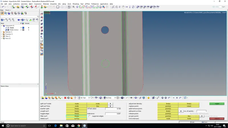
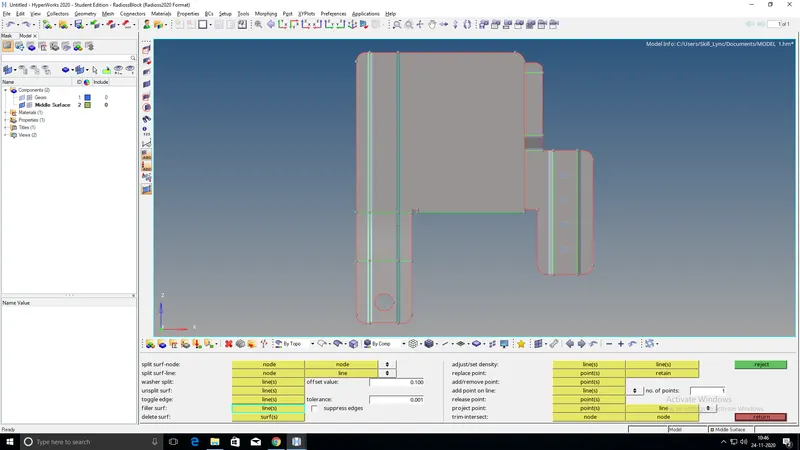
Now start meshing the surfaces. To perform meshing Go to "2D > automesh > size and bias > surfaces and select mesh type as mixed, element size as 5mm and click on the mesh.

Check for the failing elements. If any elements are failing for the quality criteria then fix it by using Quality Index or other options like distance, translate, etc (depending on the requirements for what the particular element is failing).
Once all the components have meshed within the given quality parameters, check for the edges. To check this Go to " Tool > edges > elems. Select all the displayed elements and click on find edges. If there are any edges that are disturbing the mesh connectivity then fix it by joining those elements.
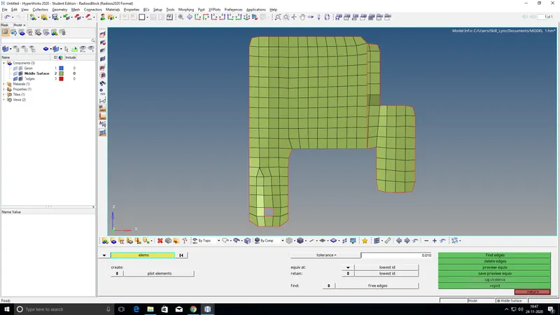
Now assign thickness to the component by first creating a property.
Once the property is assigned to the component Go to "Toolbar > select from list > 2D Detailed Element Representation" to check whether the thickness is properly assigned to the shell elements or not.
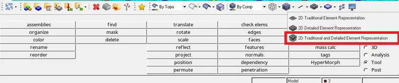
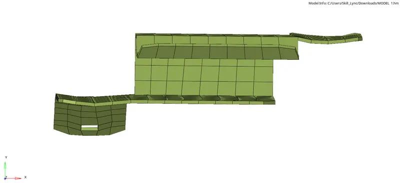
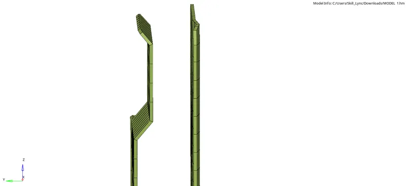
Save the model in HM format.
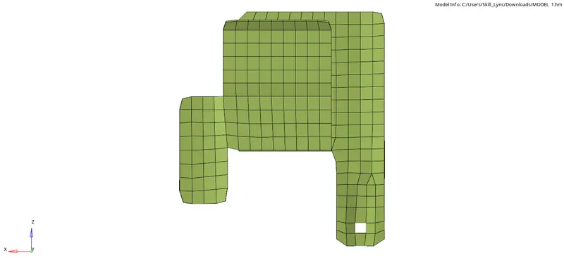
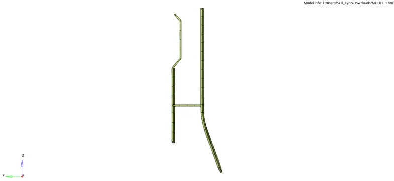
Final Output MODEL 1:
MODEL 2:
PROCEDURE:
First, import the given HM model in HyperMesh.
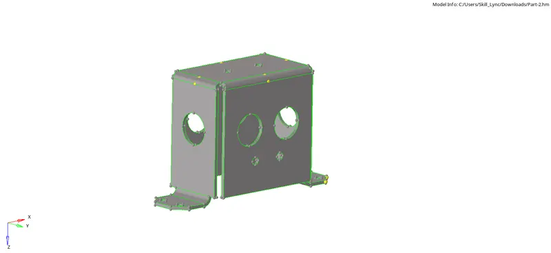
After importing the model perform geometry cleanup on the "Parent Geometry" manually.
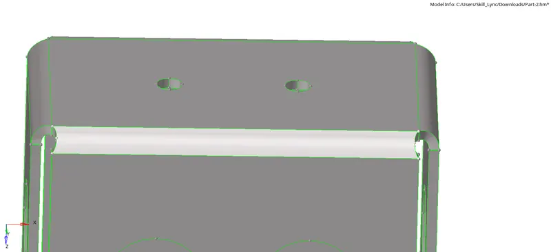
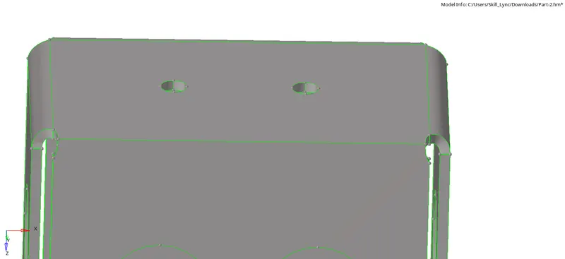
Once the geometry cleanup is completed on the parent geometry, extract the midsurface.
To extract mid surface Go to "Geom > midsurface > auto midsurface" and extract the surfaces by selecting all the displayed surfaces of the parent geometry.
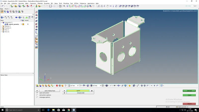
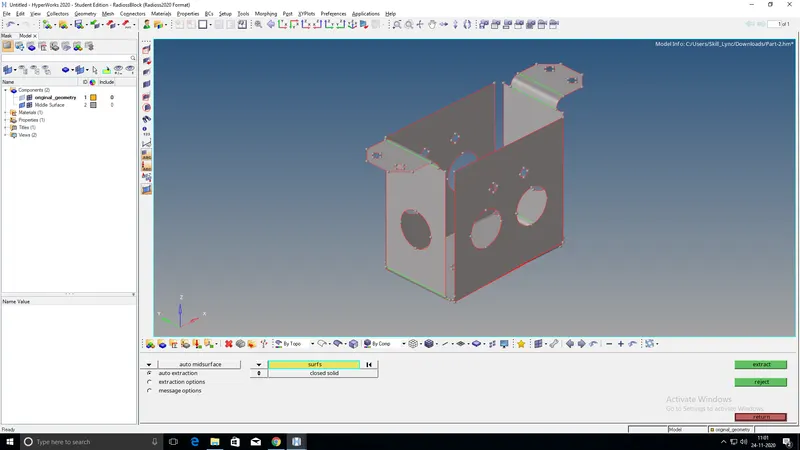
Once the midsurface is extracted perform geometry cleanup on the midsurface manually.
Fill the holes which are less than 5mm in diameter by creating a surface. Using the "filler surf" (Under Quick edit) option a surface can be created over the holes easily.
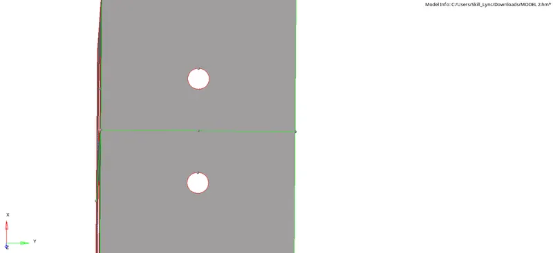

Now start meshing the surfaces. To perform meshing Go to "2D > automesh > size and bias > surfaces and select mesh type as mixed, element size as 5mm and click on the mesh.
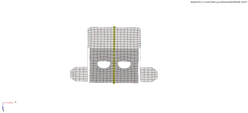
Here since the geometry is symmetrical in shape, instead of meshing all the surfaces of the component, we can only mesh a half portion of the model and then reflect it by choosing the axis and the base point easily as shown in the figure below.
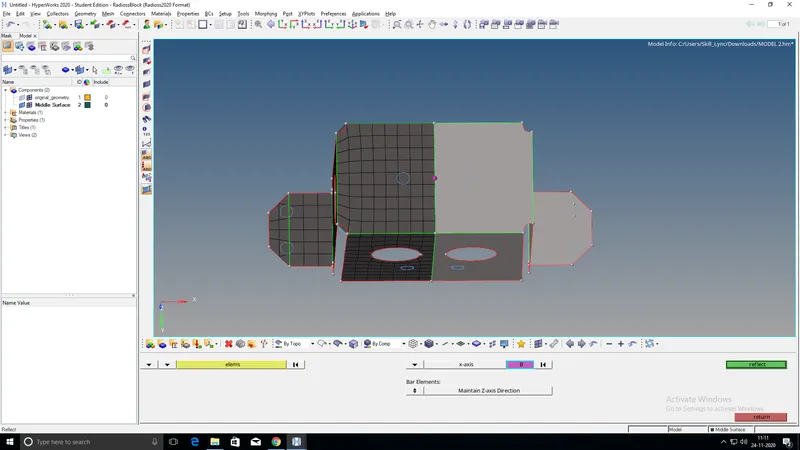
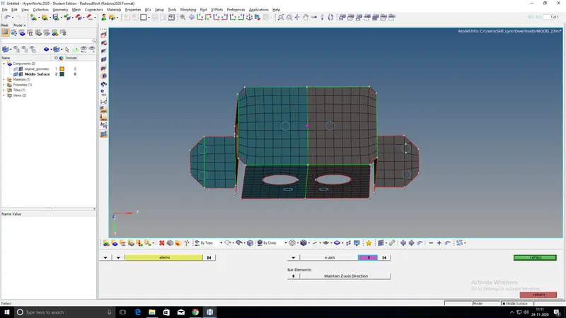
Note: The base point will be the center of our geometry.
To reflect the elements Go to "Tool > reflect > elements". First, duplicate the selected elements which we need to reflect and then choose the axis and a base point and click on 'reflect'.

Check for the failing elements. If any elements are failing for the quality criteria then fix it by using Quality Index or other options like distance, translate, etc (depending on the requirements for what the particular element is failing).
Once all the components have meshed within the given quality parameters, check for the edges. To check this Go to " Tool > edges > elems. Select all the displayed elements and click on find edges. If there are any edges that are disturbing the mesh connectivity then fix it by joining those elements.
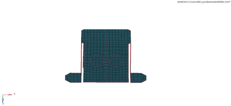
Now assign thickness to the component by first creating a property.
Once the property is assigned to the component Go to "Toolbar > select from list > 2D Detailed Element Representation" to check whether the thickness is properly assigned to the shell elements or not.
Save the model in HM format.
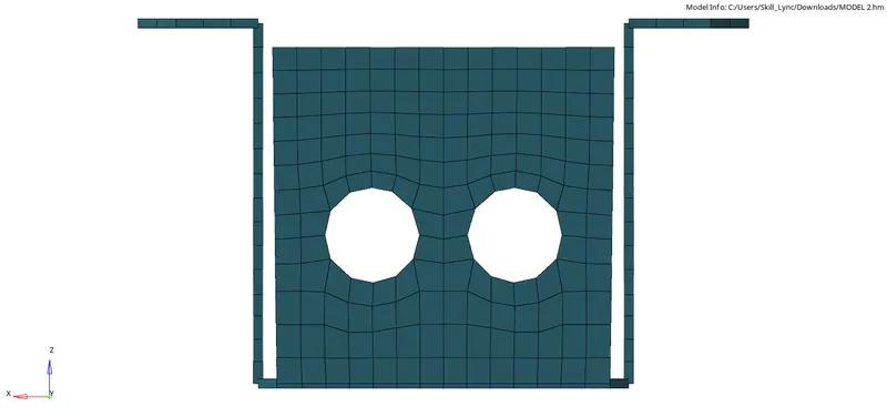
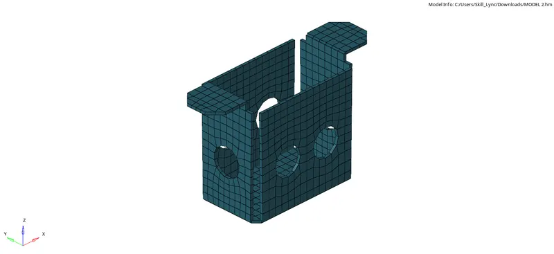
Final Output MODEL 2:
MODEL 3:
PROCEDURE:
First, import the given HM model in HyperMes.
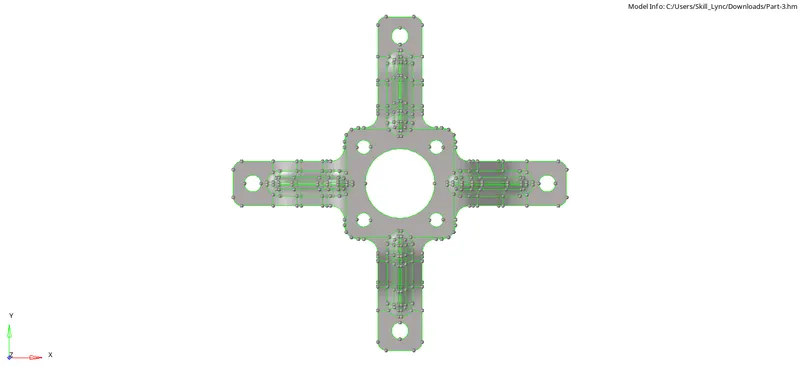
After importing the model perform auto cleanup on the "Parent Geometry". To perform auto cleanup Go to " Geom > auto cleanup > surfaces. Select all the displayed surfaces and click on autocleanup. This will toggle all those unnecessary lines where the elements can fail and also fix the holes which are less than 5mm in diameter.
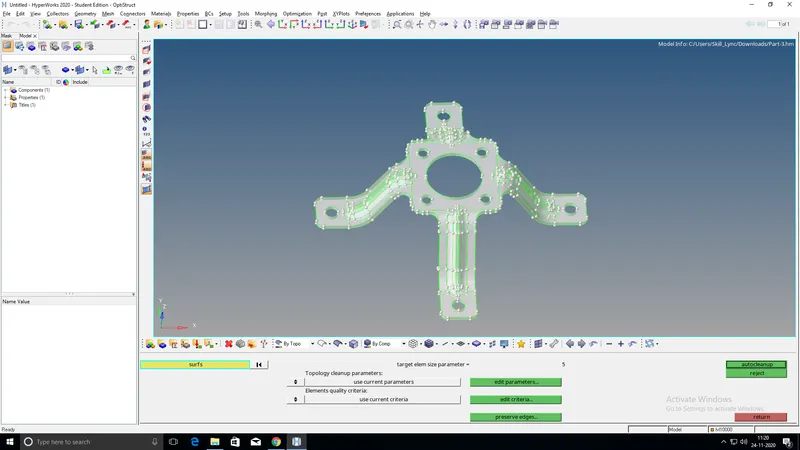
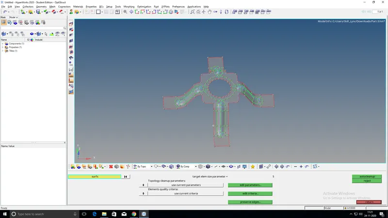
Now instead of auto midsurface we need to extract the midsurface by using 'offset' option.
To take the offset Go to "Geom > surface edit > offset. Select one face of the surface, give offset value (half value of the component thickness), duplicate the surface, check the normal vector and click on offset.

Note: always create a new component for the midsurface while using the offset option.
Once the midsurface is extracted perform geometry cleanup on the midsurface manually.
Now start meshing the surfaces. To perform meshing Go to "2D > automesh > size and bias > surfaces and select mesh type as mixed, element size as 5mm and click on the mesh.
Check for the failing elements. If any elements are failing for the quality criteria then fix it by using Quality Index or other options like distance, translate, etc (depending on the requirements for what the particular element is failing).
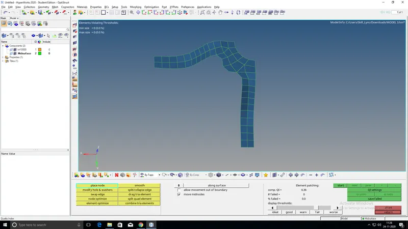
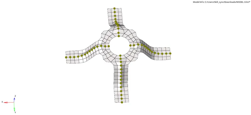
Here since the geometry is symmetrical in shape, instead of meshing all the surfaces of the component, we can only mesh a quarter portion of the model and then reflect it by choosing the axis and the base point easily as shown in the figure below.
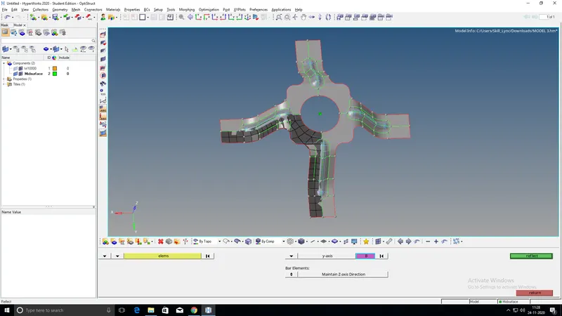
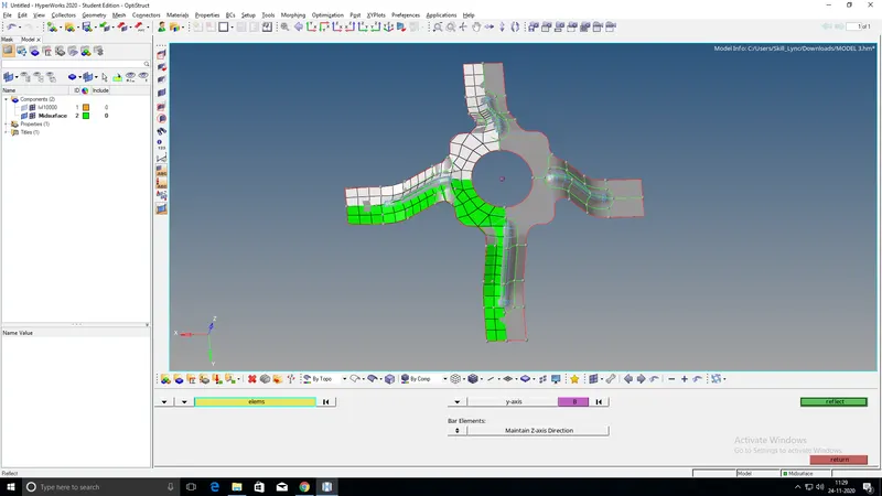
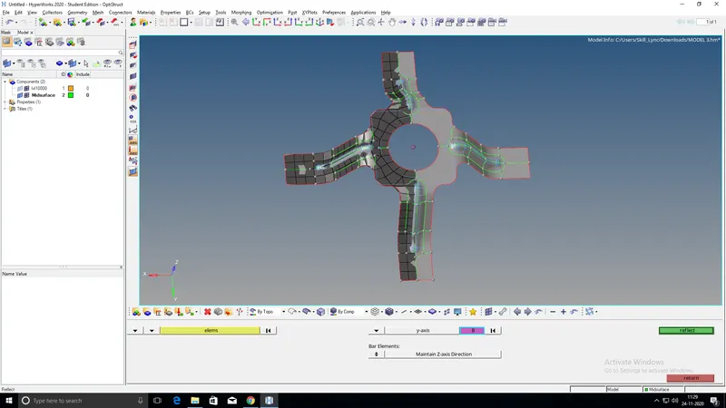
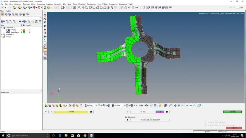
Note: The base point will be the center of our geometry.
To reflect the elements Go to "Tool > reflect > elements". First, duplicate the selected elements which we need to reflect and then choose the axis and a base point and click on 'reflect'.
Once all the components have meshed within the given quality parameters, check for the edges. To check this Go to " Tool > edges > elems. Select all the displayed elements and click on find edges. If there are any edges that are disturbing the mesh connectivity then fix it by joining those elements.
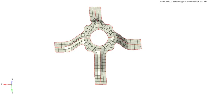
Now assign thickness to the component by first creating a property.
Once the property is assigned to the component Go to "Toolbar > select from list > 2D Detailed Element Representation" to check whether the thickness is properly assigned to the shell elements or not.
Save the model in HM format.
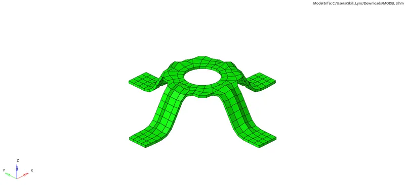
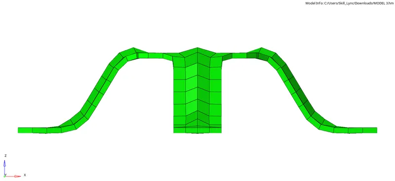
Final Output MODEL 3:
Result:
All the three given models have meshed with the given quality parameters and the properties have also been assigned based on their respective thickness.