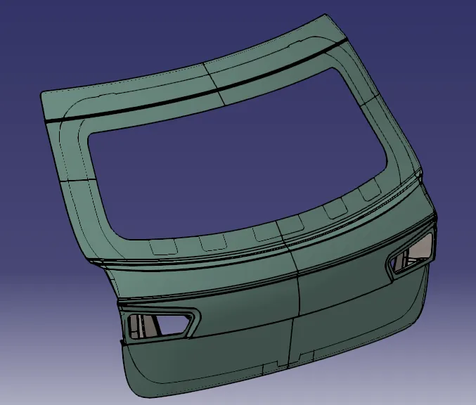
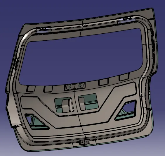
Design of backdoor
Aim:
To Design & Develop the Back Door Panel of a car using styling surface as input and also creating the necessary reinforcements and embosses.
Introduction:
Back Door:
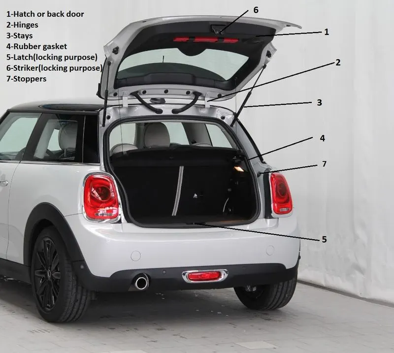
The back door is placed at the rear end of a car at which the loads can be kept. It is also called a trunk or tailgate. It consists of an outer panel, inner panel, and some reinforcements to give strength to the component. Trunk lids are made of steel which is stamped using the deep drawing process. The thickness ranges from 0.6- 0.8mm for the panels. Reinforcements size- 1-1.5 mm.
Hinges:
A hinge is a mechanical bearing that connects two solid objects allowing a limited angle of rotation between them. Two objects are connected by an ideal hinge rotate relative to each other about a fixed axis of rotation.
Latch:
The latch is a mechanical fastener that joins two or more objects or surfaces while allowing for their regular separation. It engages another piece of hardware on the other mounting surface. Depending upon the type and design of the latch, this engaging bit of hardware is known as a keeper or striker.
Gas Stay:
A gas stay or gas spring uses a compressed gas contained within an enclosed cylinder sealed by a sliding piston to pneumatically store potential energy and withstand the external force applied parallel to the direction of the piston shaft.
Procedure:
In this project, we will be creating the components of the Back Door Panel in a single assembly. The components of the Back Door Panel includes,
- Outer Upper Panel
- Outer Lower Panel
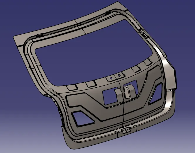
- Inner Panel
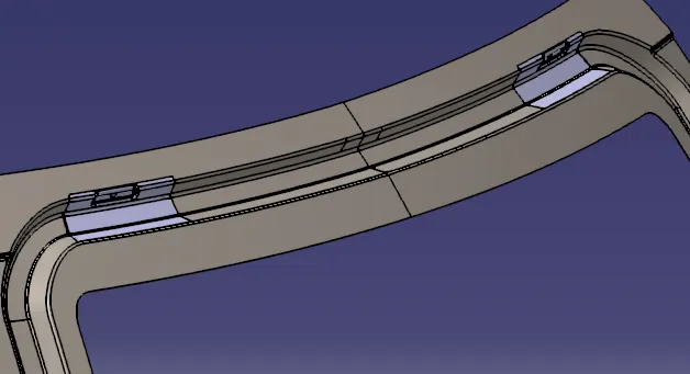
- Hinge Reinforcements (RH & LH)
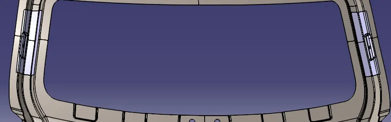
- Gas Stay Reinforcements (RH & LH)
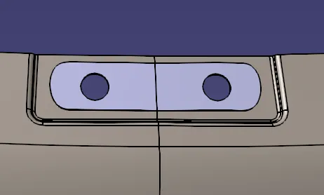
- Latch Reinforcement
Outer Upper Panel:
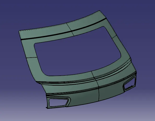
Initially, we will be creating the Outer Upper Panel by first importing the styling surface in CATIA V5.
Since the styling surface is having some issues, we need to fix this by creating a new surface in place of the irregular surface.
Note: As per the industry standards this operation is not recommended to be done by the Design Engineer. There will be a separate team whole will be working on the styling surface.
The surfaces can be created with the help of Blend, Multi-section & Spline and then the necessary fillets are provided to the sharp edges.
Once all the fillets are done make sure to check if the outer panel is offsetting/thickening to the required limit.
If the outer panel is not thickening due to sharp edges then we need to provide a bigger fillet value to avoid the sharp edges.
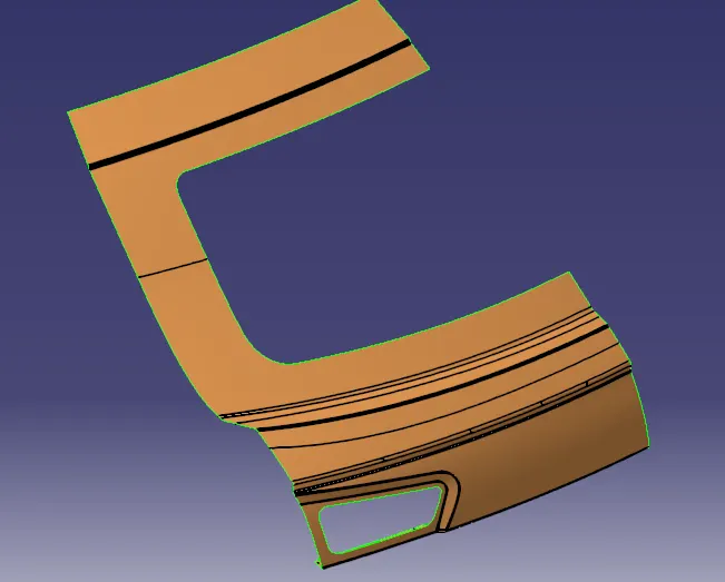
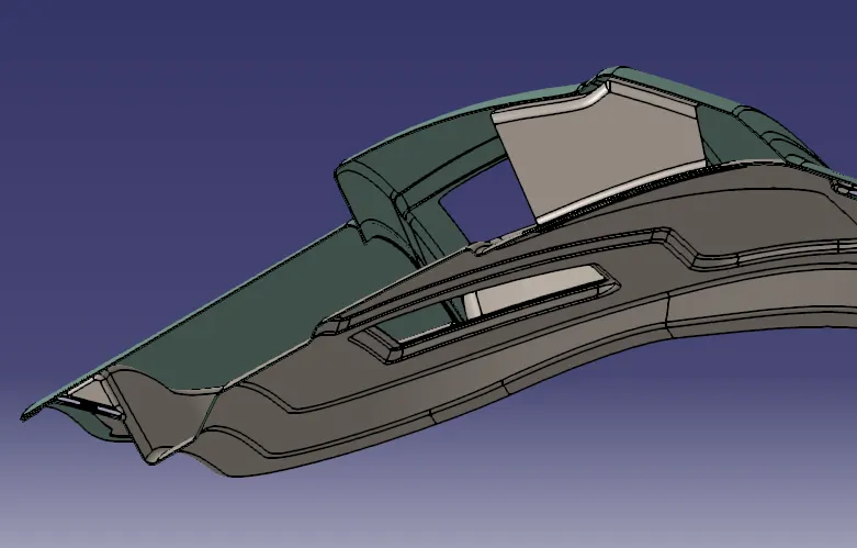
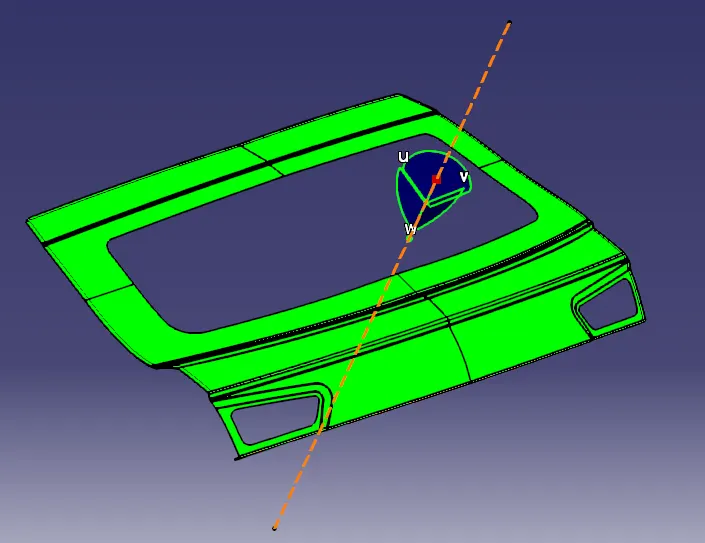
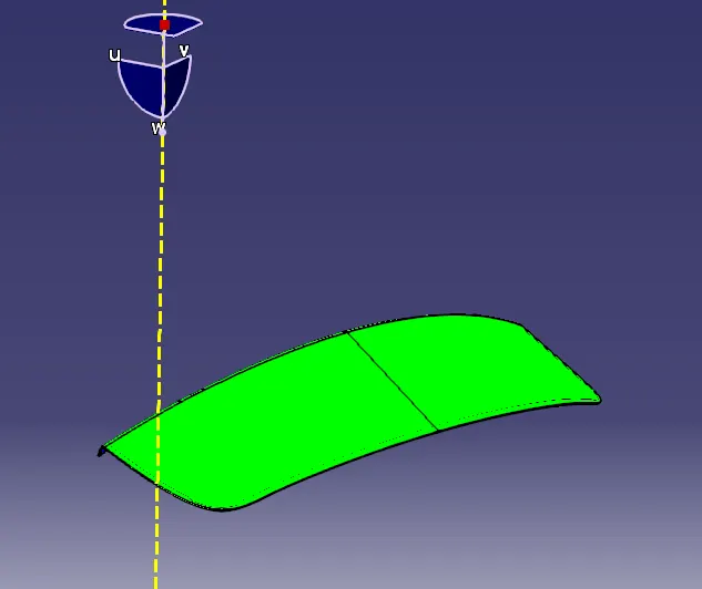
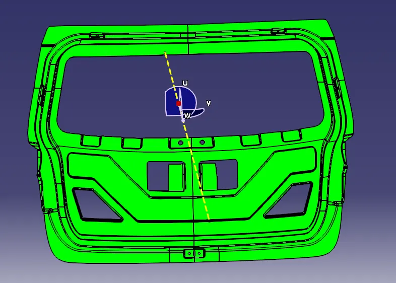
A tooling axis is also created in a direction through which most of the surfaces of the Back Door Panel are clearing the draft direction. This is done to make sure the part is manufacturable & clearing the draft direction.
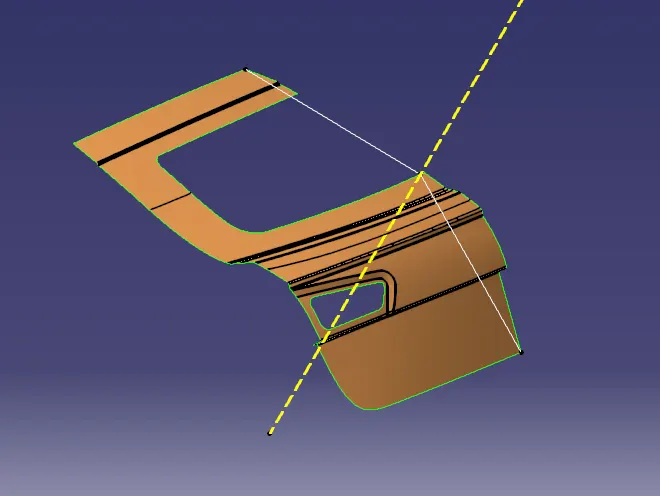
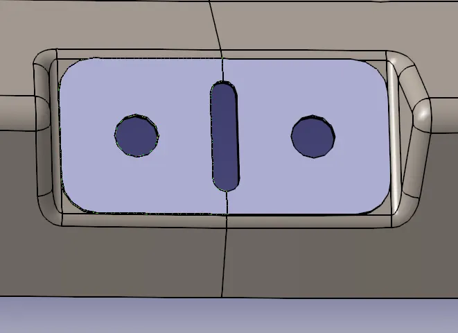
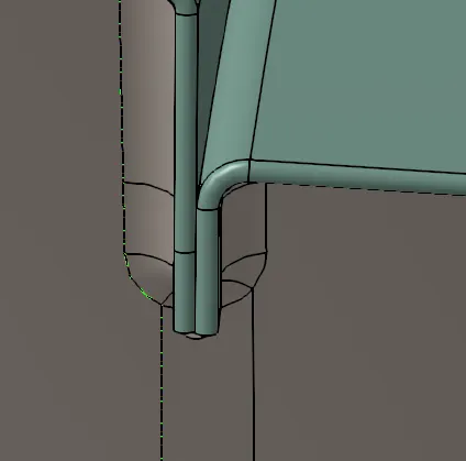
Now to create the Hemming portion for the upper panel, offset the outer upper panel to 2.65mm downwards (considering the thickness of both outer & inner panel as 0.75mm and providing a clearance of 0.2mm).
Offset the outer edges of the offset surface to 10mm using the parallel curve option.
Split the offset surface with the offset curve & make sure to check whether this surface is thickening or not. This is done to make sure the surfaces won't create any problems while thickening at the end.
Now using the Blend option create a surface joining the outer upper panel & split surface. This surface is also checked by thickening to avoid errors.
Give a Tri-Tangent filet by selecting these 3 surfaces.
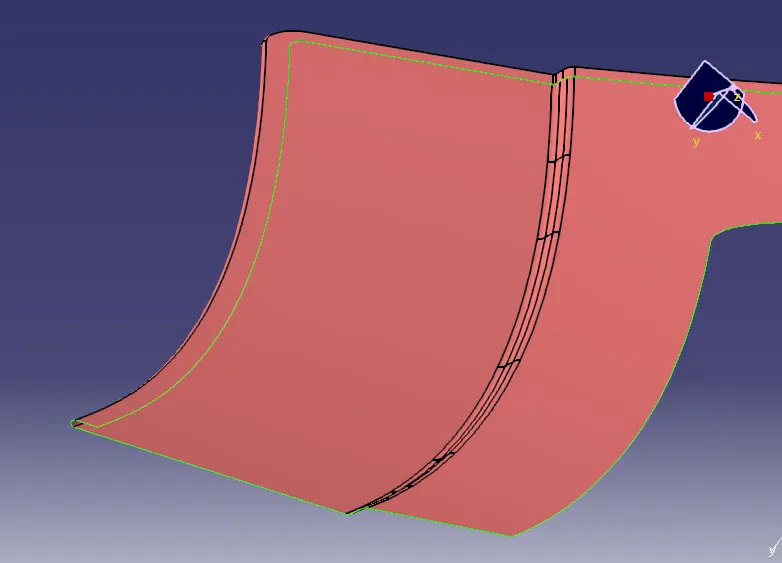
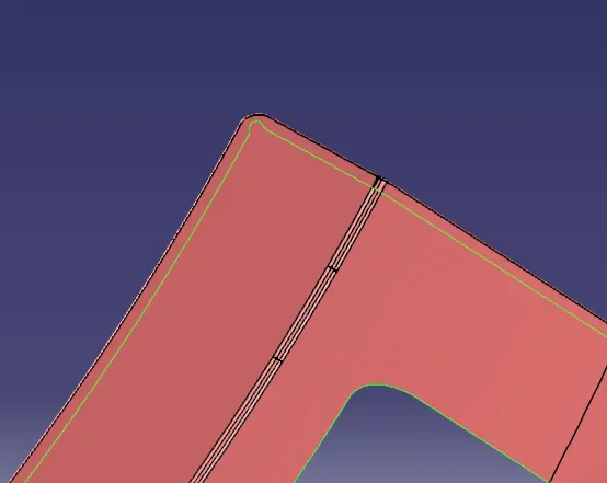
Near the corner, we will be providing relief. This will be done with the help of a parallel curve, spline & split options.
Using the relief curve and split the surface to form a relief at the corner.
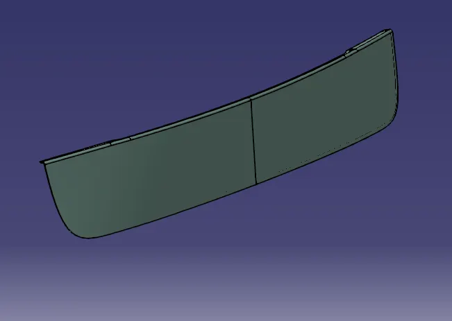
Outer Lower Panel:
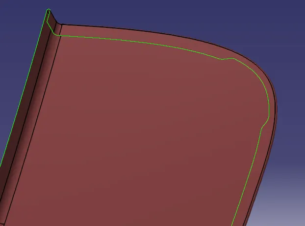
Similar operations that are performed above are followed here to create the Outer Lower Panel.
Offsetting the Outer Lower Panel to 2.65mm.
Offsetting the edges to 10mm & splitting the offset surface with it.
Joining these 2 surfaces with Blend & Providing Tri-Tangent fillet.
Inner Panel:
First, offset the outer panels to 1.7mm downwards (Outer Panel Thickness=0.75mm downwards & Inner Panel Thickness=0.75mm upwards and a clearance of 0.2mm is maintained).
Note: This offset surface of 1.7mm will be the top surface of the inner panel.
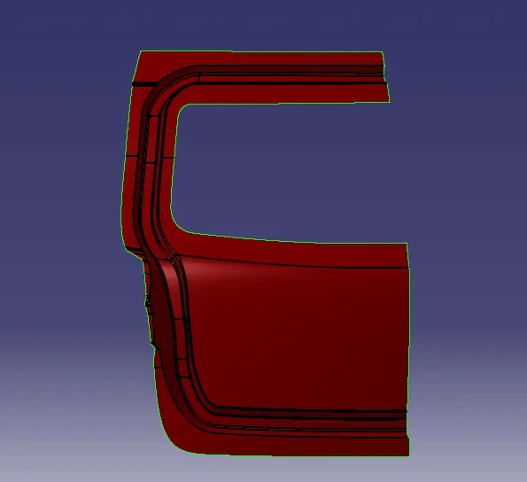
Now offset the outer upper panel to 25mm downwards and use the parallel curve option to cut the elements (to create a Sealing Flange) as shown in the below figure.
Offset the Outer Lower Panel to 60 mm downwards and use the same operations as above to create the remaining Sealing Flange.
Join the Sealing Flanges by creating a surface between them using Spline & Multi-Section Surface.
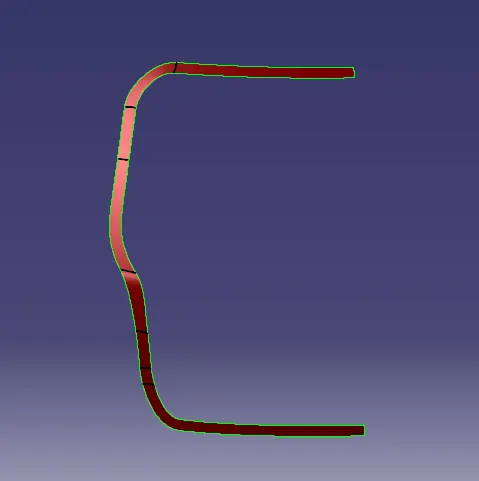
Using the Sweep option, create a surface with an angle of 25 degrees with the tooling axis.
Using the offset surface of 1.7mm, trim this sweep surface.
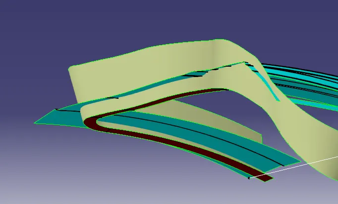
Now to create the windshield area of the inner panel, extract the surfaces nearer to that area from the 1.7mm offset surface.
Sweep the sealant flange inner edges with an angle of 25 degrees inside and trim it with windshield extract.
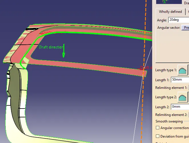
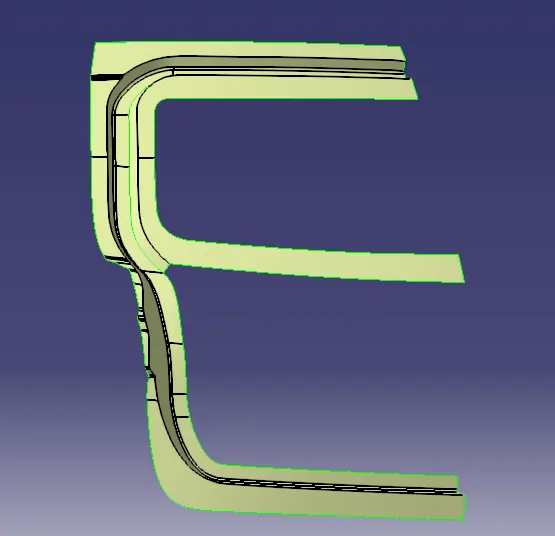
Similarly, create the lower side surface using the spline & multi section option and join them.
Creating surface for applying mastic:
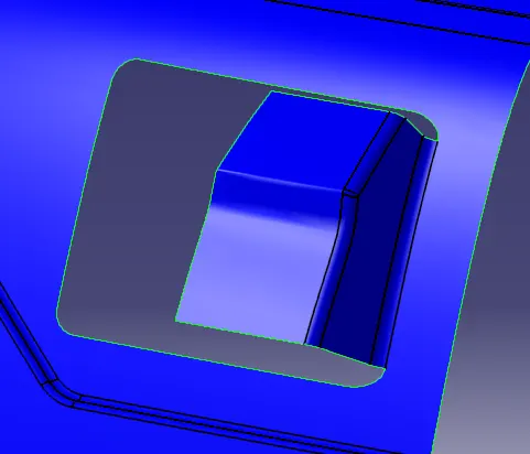
To apply the mastic, we need a surface which is having a 5mm clearance with the outer panel.
A cutout of rectangular shape is provided below the windshield area and using its edge a surface is created perpendicular to its base surface.
Now to create a surface for applying mastic first, offset the outer panel surface to 5mm.
Trim the outer panel with the sweep surface and remove the excess portion of the mastic surface by using the split option.
Embossments:
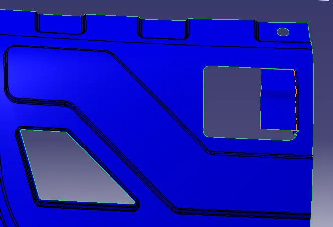
To reduce the impact of an accident on the Back Door Panel, Embossments are created below the windshield area.
Create a sketch for embossments in such a way that the forces acting during an impact results in lesser damage to the occupants & as well as to the vehicle.
Project this sketch on the surface and split the surface using it.
Sweep the edges inside and using its base surface, trim these sweep surfaces to form the embossments.
Follow the same procedure for the embossments at the windshield area as well.
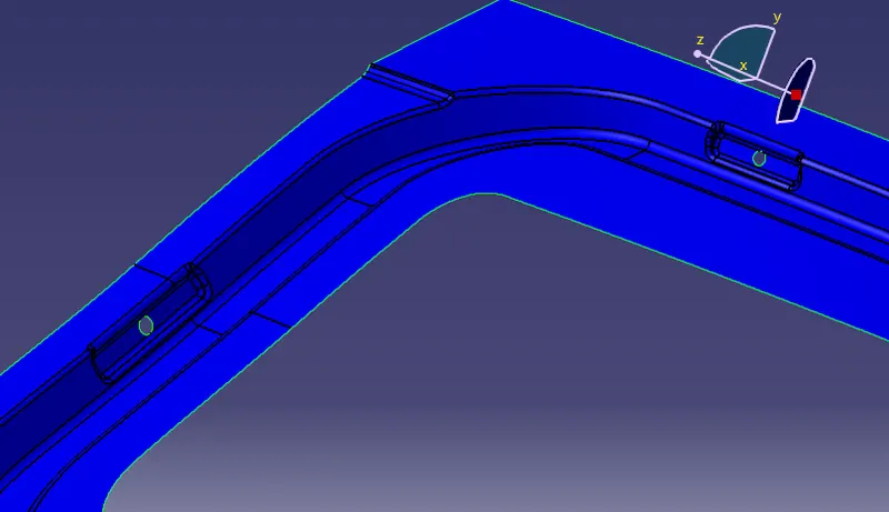
Hinge Embossment:
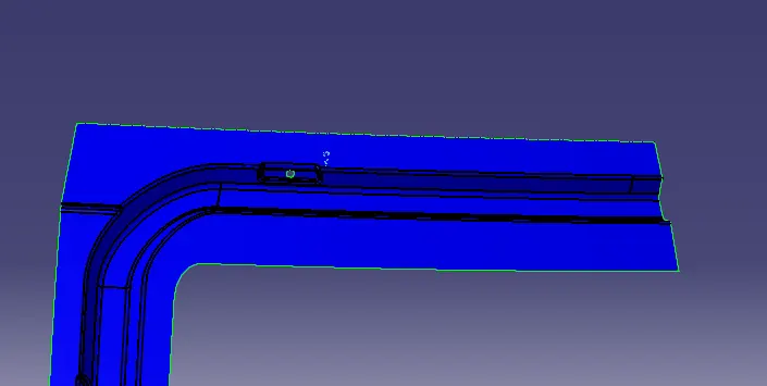
A similar procedure is followed for creating the hinge embossments except that the top surface of the hinge should be created with zero surface area.
This means that the sweep surfaces cannot be trimmed with their base surface & hence an additional surface is created.
This surface is generated by first creating a straight line following the axis. Now extrude this line and trim the sweep surfaces with the extruded surface.
Make a hole at the centre of the top surface and this will give us the hinge embossment.
Gas Stay Embossment:
Gas Stay Embossment are created at the sides of the inner panel by following the same procedures as mentioned in the case of hinge embossments.
Latch Embossment:
To create a Latch Embossment we first need to create a mid-point of the hinges.
Since the latch is not provided to us as input, we will be considering a centre point for the latch and drawing a line coinciding with this point.
Note: Let us say this line as a "tangent line" for understanding the purpose.
Using the mid-point of hinges, draw a circle making a tangency with the "tangent line".
Now to create an embossment for the latch we need to create another line that will be making a 90-degree angle to the "tangent line".
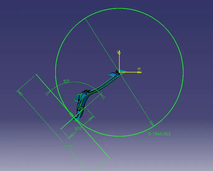
Extrude this 90-degree line and this will give us the top surface of the Embossment.
Sweep the edges of the extruded surface with a 10-degree angle outwards to the "tangent line".
Join the sweep surfaces with the extruded surface and trim the main surface with the joined surface.
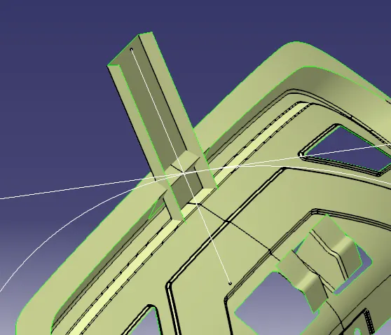
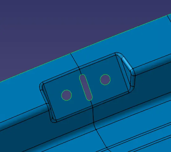
Create a cutout at the centre and give the required fillets. This will give us the Latch Embossment.
Reinforcements:
To create the reinforcements, select the surfaces with the nearby areas and extract them.
Cut the excess portion by first creating a line on the surface and then split the surface using it.
Offset the surface to 0.75mm.
Reinforcements for all the parts are created by following similar operations as mentioned above.
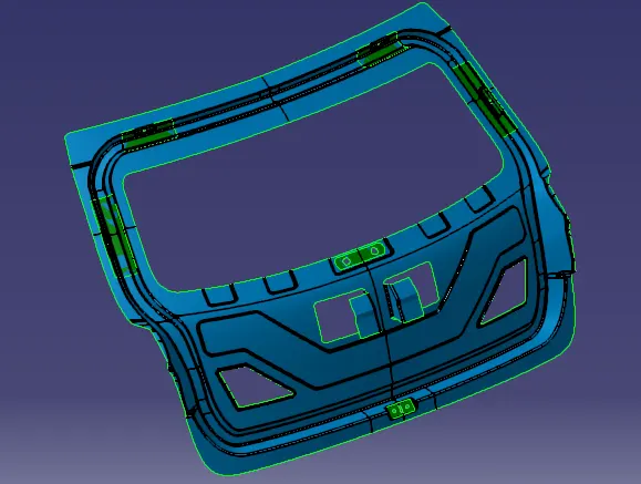
Generating Solid:
Use the Thick Surface option in Part Workbench to generate the solid. The thickness for all the components of the Back Door Panel is given below.
Outer Upper Panel: 0.75mm (Thicken Downwards)
Outer Lower Panel: 0.75mm (Thicken Downwards)
Inner Panel: 0.75mm (Thicken Upwards)
Reinforcements: 1mm (Thicken Upwards)
Result:
The Design & Development of the Back Door of a car is completed with all the necessary reinforcements and embosses.
CAD Models:
Outer Upper Panel
Outer Lower Panel
Inner Panel
Hinge Reinforcement
Gas Stay Reinforcement
Wiper Reinforcement
Latch Reinforcement
Hemming region
Section View
Draft Analysis:
Final Model: