Frontal Crash Analysis - BIW of Neon Car
Aim:
To set up the case for FRONTAL CRASH - BIW OF NEON car and successfully running the simulation while also observing the errors and energy changes.
SOFTWARE:
HYPERWORKS 2020
USER PROFILE:
RADIOSS
OBJECTIVE:
The objective of the challenge is to follow the below-given steps:
- Check the unit system and either follow[Mg mm s] or [Kg mm ms].
- Create an appropriate interface, friction 0.2, and recommended parameters.
- Make sure of no penetrations and intersections.
- Correct rigid bodies if any issues.
- Create a rigid wall with friction 0.1.
- Compare the model weight with the full-scale 300k nodes model and use added masses to reach the target weight of 700kg while getting CG about the required range.
- Initial velocity 35 mph.
- Use a model checker to ensure good quality.
- Time-step: 0.5 to 0.1 microseconds.
- Run 80 ms.
PROCEDURE:
Importing the model:
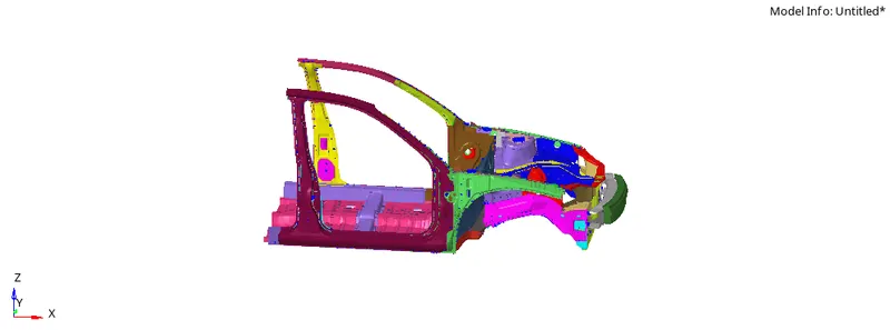
First import the starter file (.rad) in HYPERMESH by going to menu bar > file > import > solver deck. Browse the file from the system and import it.
Checking for the units:
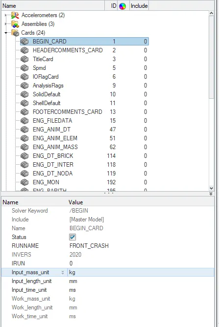
After importing the model, check for the units. In this project, we are following the [Kg mm ms] unit system. In order to change the unit system Go to Tab bar > Cards > Begin card.
Creating the interface:
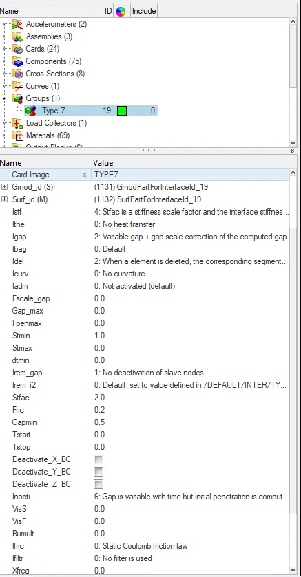
Now in order to create the interface, Go to Tab bar > Groups > right-click on it and create. In this project, we are creating a Type 7 interface. Set the below-recommended properties to create a Type 7 interface.
Note: Delete all the previous interfaces which are present under the groups.
Card image: Type 7
Gmod_id (S) (slave entities) : select all the components
Surf_id (M) (Master entities) : select all the components
Istf : 4 - It is the gap for stiffness definition, it is the interface stiffness which is the minimum of the master and slave stiffness.
Igap : 2 - It is the gap option flag. Igap = 2 is Variable gap + gap scale correction of the computed gap.
Idel : 2 - It is the node and segment deletion flag. When a 4-node shell, a 3-node shell or a solid element is deleted, the corresponding segment is removed from the master side of the interface. It is also removed in case of explicit deletion using Radioss Engine keyword /DEL in the Engine file.
Additionally, non-connected nodes are removed from the slave side of the interface.
Stmin : 1 - It is the minimum stiffness value that can be used only if Istf value is not equal to 1.
Irem_gap : 1 - The option Irem_gap is used to deactivate slave nodes that are close to elements. But in this case, since we put the value as 1 that means there is no deactivation of slave nodes.
Stfac : 2 - Stiffness scale factor applied to the master side of the interface (if Istf is not equal to 1).
Fric : 0.2 - Coulomb friction
inacti : 6 - Deactivation flag of stiffness in case of initial penetrations. But in this case, the value is set to 6 which means the gap is variable with time but initial penetration is computed.
Gapmin : 0.5 - Minimum gap for impact activation.
Iform : 2 - Stiffness (incremental) formulation.
Creating a rigid wall:
To create a rigid wall Go to Tab bar > right-click > create > rigid wall.
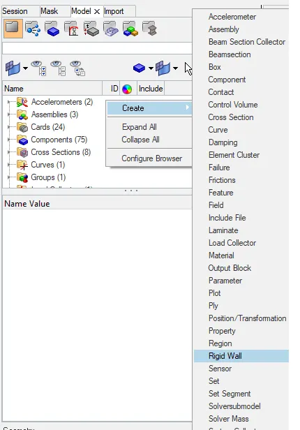
Now under the rigid wall properties give the below-mentioned values and click on the arrow to select the base node (M).
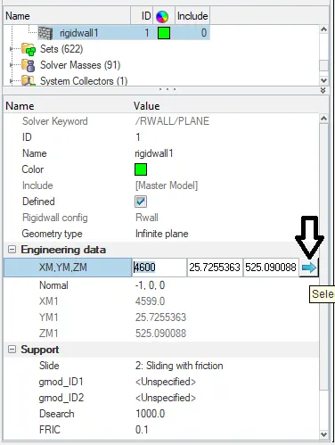
Geometry type: infinite plane
XM, YM, ZM: select the base node at which we want to create the rigid wall
Normal: -1, 0, 0 - In order to give a normal direction, put -1 in x coordinate (since the car is moving in x plane).
Slide: 2 - sliding with friction
Dsearch : 1000 - Distance for slave search / Search distance
Fric : 0.1 - Friction
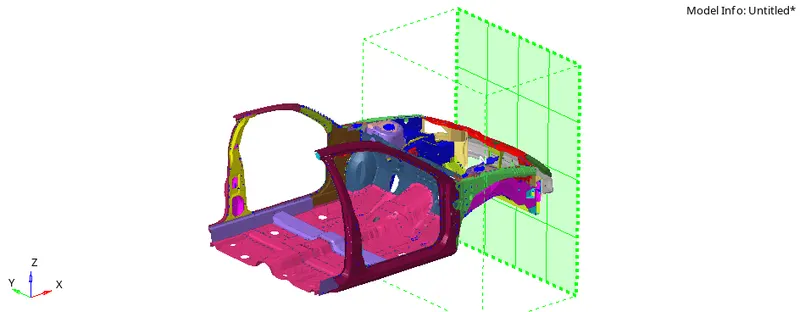
Creating a COG point and balancing the mass:
The center of gravity should be exactly right below the driver’s seat (at the center of the body). To have COG at that position we need to balance the mass of the entire component/body.
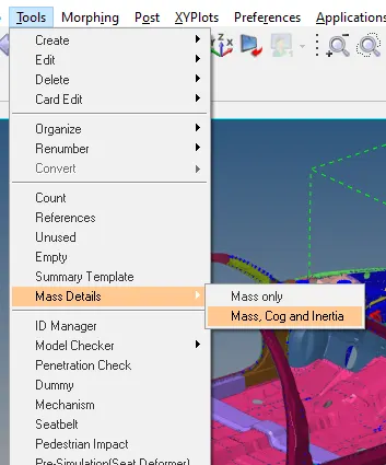
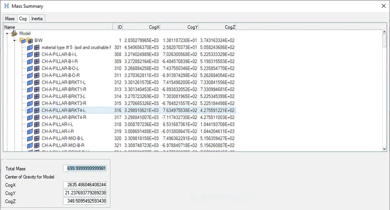
First, check the current COG point and total mass of the body so that based on the requirements we can add the mass. In order to check the current mass and COG of the body Go to the menu bar > Tools > Mass details > Mass, Cog, and Inertia.
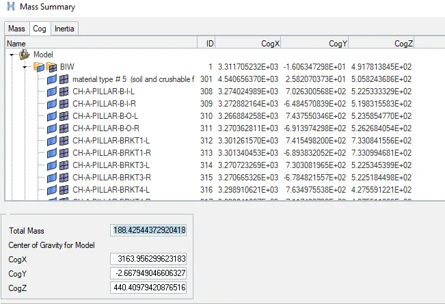
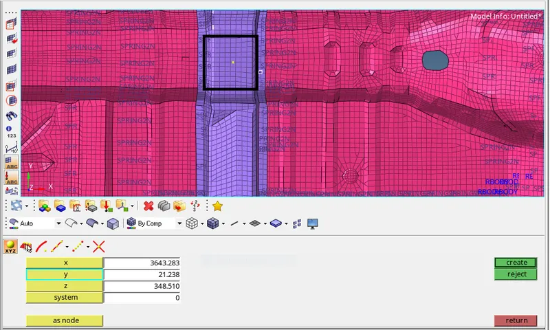
To view the COG point on the graphical screen we need to create a node by giving Cogx, y and z values. Go to the main menu page > Geom > nodes. Give the above COG values in x,y, and z respectively, and click on create to view the COG point.
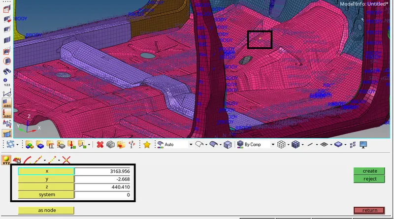
Since the COG point is not at the center of the body, add some mass in such a way that the COG point is shifted at the center.
Always try to add mass at the lower portion of the body because in crash analysis the height of the COG also matters a lot.
To add mass Go to Tab bar > right click on the tab area > Create > Solver Mass. Select Mass type as 0 (it will add mass value on each node) and Mass value as 0.5.
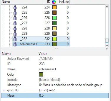
Right-click on the gmd_id and click on create to select the nodes where we want to add the mass.
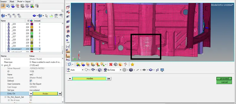
Now the COG is at the center of the body but the mass of the body is still 350 kg approx. To reach the required mass of 700kg, add some more mass at the center of the body (since the COG is already at the center).
Note: Create a new Solver Mass (Solver Mass2) to add the remaining 350 kg mass).
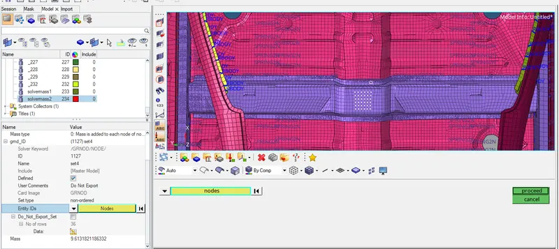
Now the COG point and total mass of the component/body have reached the required range.
Applying initial velocity:
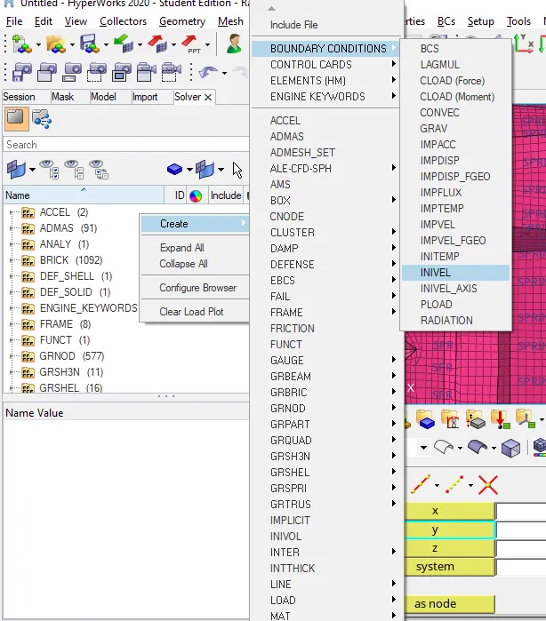
To create initial velocity, Go to Tab bar > right click on the solver browser > create > BOUNDARY CONDITIONS > INIVEL.
Right-click on the gmd_id and click on create to select all the nodes of the components and click on proceed. Give the velocity value as 15.65 in x-direction.
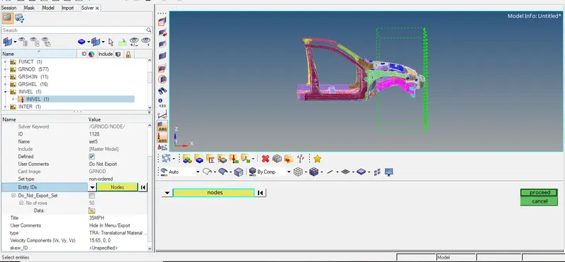
Note: Initial velocity is given as 35mph. We need to convert this mph value to the current unit system i.e, mm/ms. So 35mph will be equal to 15.65 mm/ms.
Penetration and intersection check:
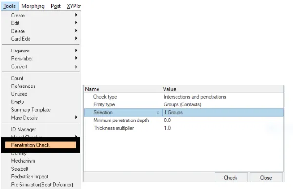
To check the penetrations, Go to menu bar > Tools > Penetration check. In the entity editor, click on the selection, and under groups, select the type 7 contact that we have created. In the Tab bar, we can view if there are any penetration and intersection in the model. After running the check, we can see that there is no penetration and intersection in the model.
Checking for errors:
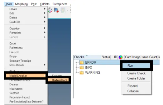
To avoid any kind of problems during simulation, we need to perform a check for errors. To perform this operation Go to menu bar > Tools > Model Checker > RadiossBlock. In the tab bar, a new browser will open, right-click on ERROR and run it.
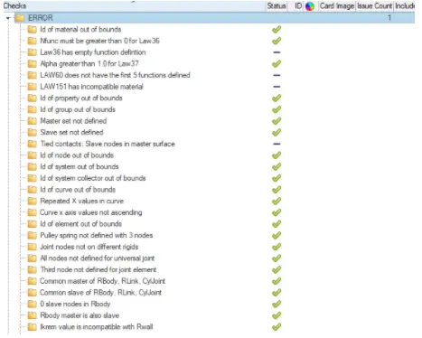
If there will be any errors present in the model then it will be highlighted with a cross mark. Clear the errors if there are any (currently there are no errors in the model).
Applying Time-step and run-time value:
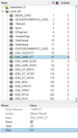
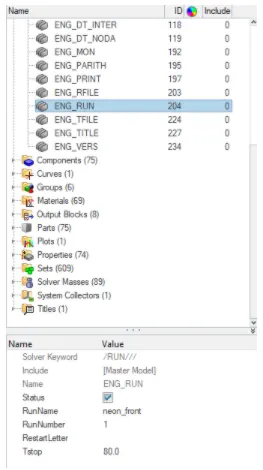
To apply the time step value, Go to Tab bar > cards > ENG_ANIM_DT. Change the Tfreq value to 0.5.
To apply the run-time value, Go to Tab bar > cards > ENG_RUN. Change the Tstop value to 80.
Output requests:
- Sectional force in the rails at the location of indicated node 174247.
- The axial force received on the rails from the bumper.
- Shotgun cross-sectional forces.
- A pillar cross-section.
- Acceleration curve received on the accelerometer at base of B pillar (on B pillar rocker).
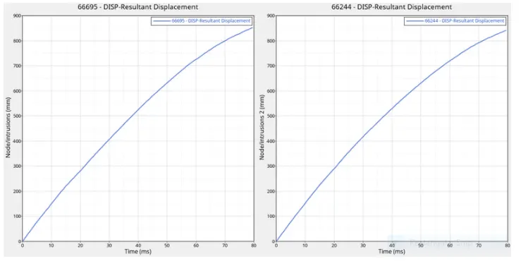
- Intrusions on the dash wall 66695,66244
Creating CROSS-SECTIONS:
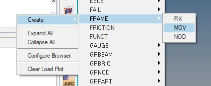
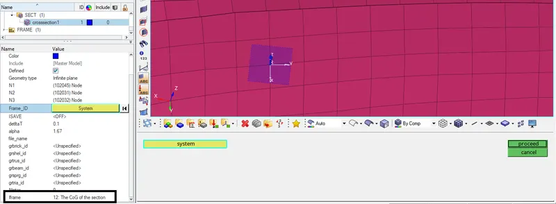
To create a cross-section, we also need to create a frame in order to define the local coordinates of the cross-section. Go to Tab bar > under solver browser > right click and create > Frame > MOV. select three nodes and click on proceed to create a movable frame.
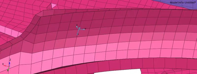
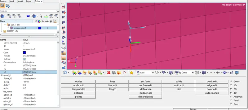
Now under Frame ID, select the frame which we have created to define the local coordinates for the cross-section and also set the iframe value as 12.
Right-click on grshell_id and create to select the elements for creating a section.

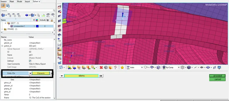
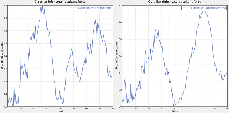
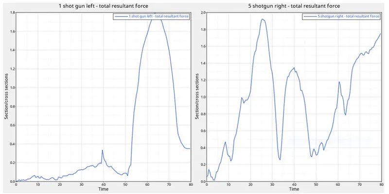
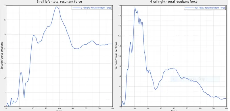
A cross-section has been created at A-pillar. Similarly, we need to create CROSS-SECTIONS for BUMPER, RAIL, and SHOTGUN.
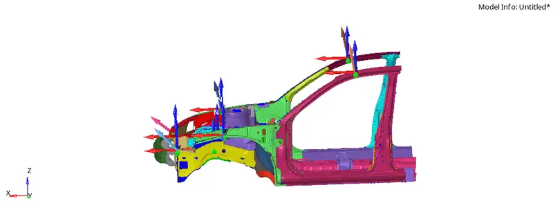
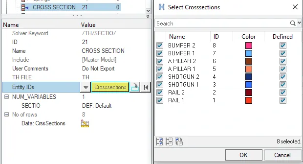
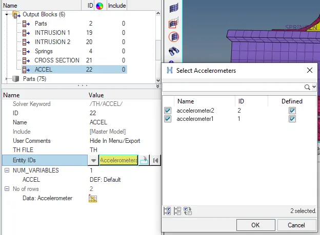
After creating all the cross-sections, we need to call these sections in the “Output Block”. To perform this operation Go to Tab bar > under model browser > right-click on output block and create > name the new card as cross-sections > under Entity IDs select all the cross-sections which we have created and click on ok.
Creating Accelerometers:
We need to create Accelerometers at the base of B pillars, so to perform this operation Go to Tab bar > under solver browser > right click and create > Accelerometer. Under node_id select the node where we want to create the accelerometer and give Fcut value as 1.65.
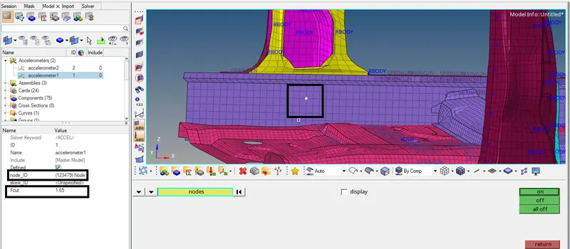
After creating the accelerometers, we need to call it in the output block. The procedure for calling the accelerometers in the output block is same as mentioned for the cross-sections.
Creating Intrusions:
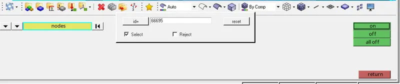
We need to create the intrusions at the given node ids which are 66695, 66244. To find these nodes Go to the main menu page > Tool > numbers > click on nodes to search by id. Enter the node id and click display on.

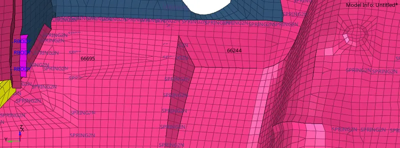
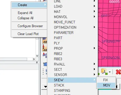
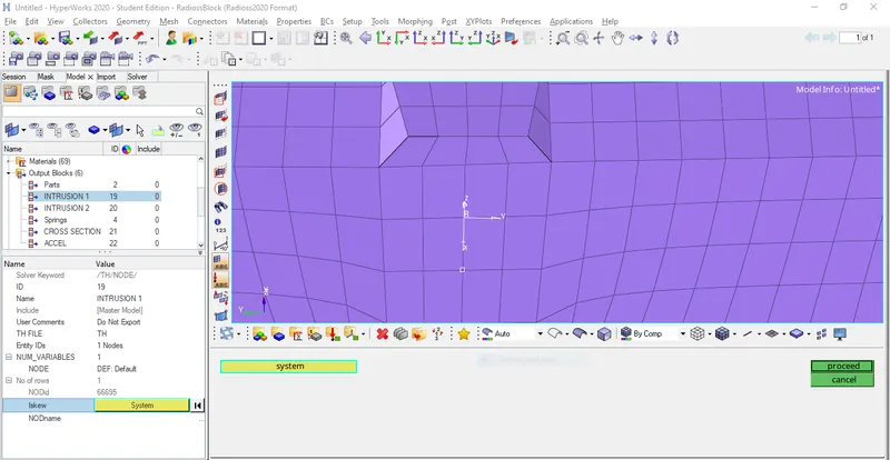
Now Go to Tab bar >under solver browser > right click and create > SKEW > MOV. select the origin node (N1), Axis node (N2), and plane node (N3) and this will create the coordinates (system) for the intrusion.
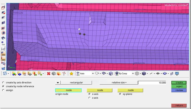
The coordinates for both the intrusions has been created.
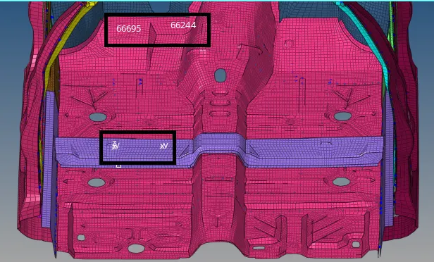
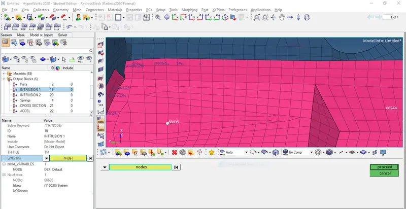
Now we need to call these intrusions in the output block. we need to create two intrusions (intrusion 1 and intrusion 2) in the output block. While creating intrusions, under Entity IDs select the node (6695) for intrusion 1 and (66244) for intrusion 2 and select the respective skews in Iskew to define the coordinates
Errors faced and the steps to solve it:
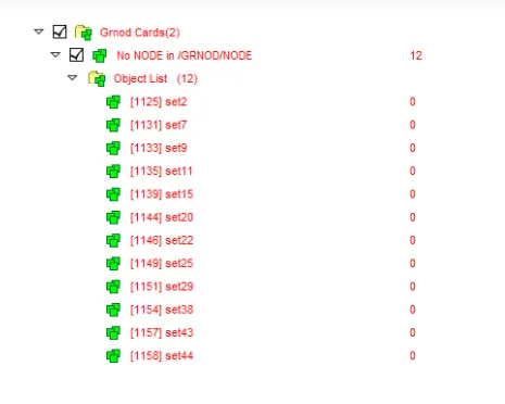
The final part of any simulation is checks and bug fixes during and after simulation. The only errors which we faced after setting up the case for simulation were empty sets. While creating the Center of gravity (COG) point these sets may get created and it can be deleted. Though while checking the errors through the model checker in Hypermesh it won’t show the error of empty sets but while checking for errors in HyperCrash these errors can be found and deleted easily.
To run the model checker in HyperCrash, first export the set up case file and open it in HyperCrash. To open HyperCrash, Go to menu bar > Applications > HyperCrash (select the unit system and run). This will open the HyperCrash window. To run the model checker in HyperCrash Go to menu bar > Quality > Model Checker > Run. Now delete the empty sets and again export it. Now to run the simulation, open this file in Hypermesh and make sure to delete the unsupported cards. These unsupported cards are created by HyperCrash while exporting the file and it doesn’t make any change in the model.
Note: It is advisable to run the model checker in HyperCrash before running the simulation in HyperMesh because it gives more minute and important information regarding the errors which we can face during the simulation.
Running the simulation:
After completion of all the tasks on the model, run the simulation and save it in a separate folder. To run the simulation, Go to the main menu page > Analysis > Radioss. Click on "save as" to change the file directory. Tick the box of include connectors and under the options tab, type the value as -nt 4, and click on Radioss to run the simulation.


Once the simulation is started, HYPERMESH will popup a box in which it will show the simulation process.
After the simulation run is completed, a message will show on the popup screen as the job is completed.
All the files which were generated during the simulation run such as .h3d file, T01 file, starter file, engine file, etc will be stored in the input file directory.
Viewing Animation:
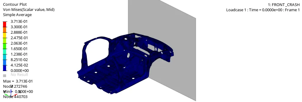
To view the animation, open HyperView. To perform this operation, Go to Tool bar and from the client selector open HyperView and update the animation file (.h3d) in it. Select this file from the directory folder (new folder which we created for inpute file directory). After updating it click on apply to view the animation.

Now click on the play button to view the animation.
Plotting the Graphs:
To plot the graphs, open HyperGraph 2D. To perform this operation, Go to Tool bar and from the client selector open HyperGraph 2D and update the time history file (TO1) in it. Select this file from the directory folder (new folder which we created for inpute file directory).

After updating it, select the cross sections and other energies (individually) which we need to plot and click on apply.
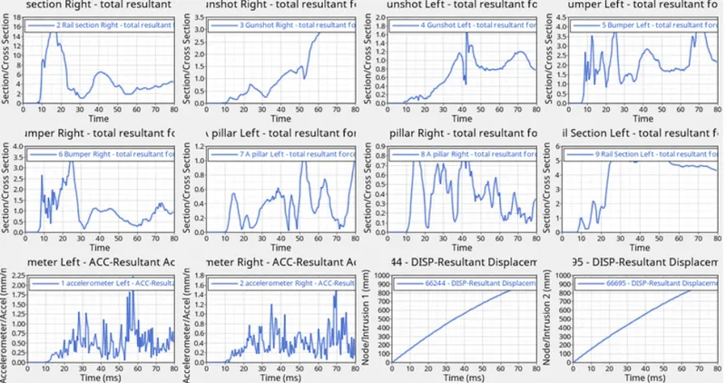
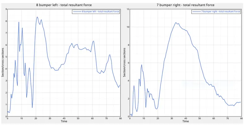
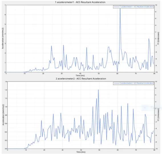
The above graphs shows all the Accelerations, Cross-sections and Intrusions of the car.
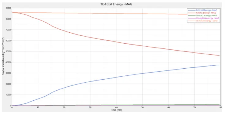
The graphs for Internal energy, Kinetic energy, Contact energy, Hourglass energy and Total energy vs Time is plotted below.
ENERGIES:
CROSS-SECTIONS:
A-PILLAR:
SHOTGUN:
RAIL:
BUMPER:
ACCELEROMETER:
INTRUSIONS:
OBSERVATIONS:
A few important points have been mentioned below after observing all the graphs for cross-sections, accelerometers, intrusions, and energies.
It can be observed from the animation that the frontal portion of the car is getting deformed very quickly because of high stresses being developed at the point of crash. But after a certain point, we can observe that less deformation is taking place in the body. This is due to the cross-sections which help in better force distribution in the body. Because of the better force distribution, there will be less load in a particular region, for example, less impact in the dash wall, which results in fewer injuries to the occupant.
From the energy graph, we can observe that the contact energy and hourglass energy are very constant. This is because there is no penetration and intersection of elements.
Contact energy = penetration value * contact force.
Since we have performed the penetration check and there were no penetrations found, which helps in less contact energy being developed in the body.
Hourglass energy is constant in this case because we have used fully integrated elements and recommended parameters for the property definition.
Note:
The normal value for contact energy : 0% to 5% of the total energy
The normal value for Hourglass energy: 10% to 15% of the total energy (when using under integrated elements)
The total energy is the sum of internal energy, kinetic energy, contact energy, and hourglass energy. Since internal energy is decreasing and kinetic energy is increasing the total energy results in a constant value which can be observed from the graph.
The change in acceleration graphs is drastic due to the sudden impact of the crash. The graph plotted here for the accelerometer is during the crash. If we compare the graph of the accelerometer before the crash then it will be constant as the car is not having any sudden change in speed.
PHRASES USED:
Below we have briefly discussed the important phrases which we have used in the above procedure.
BIW:
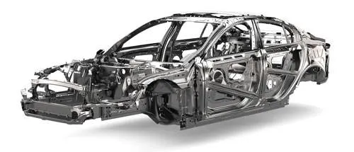
Body in white simply called as BIW is a manufacturing stage in automotive industries where all the components of a car body (before painting), barring moving parts (e.g., hoods, fenders, etc.), trims (e.g., glass, seats, etc.), or chassis subassemblies, have been welded together. All these sheet metal components are welded together to form a vehicle structure.
INTERFACES:
Interfaces are defined to model how parts interact when they come into contact with each other. In this project we are creating a Type 7 interface.
Type 7 interface:
Type 7 interface is a node to surface type of contact. It is a general purpose contact and is used to simulate all conditions. It provides a cylindrical gap area around the edges which makes it more accurate. The main advantage of interface type 7 is that the stiffness is not constant and increases with the penetration preventing the node from going through the shell mid-surface.
RIGID WALL:
Rigid walls allow for an easy way to define an interface between a rigid surface and nodes of a deformable body. A rigid wall is defined by a surface type and a group of slave nodes. It is a concrete wall which will be fixed in one place. It is plotted in this case to perform a crash analysis on the body. It can sustain enough load to perform a crash analysis.
Center of gravity (COG):
The Center of gravity simply called COG is a point from which the weight of a body or system may be considered to act. It is very important that the COG should be at the center of the body during crash analysis so that the animation of the crash looks like a real-time scenario.
Initial velocity:
Initial velocity is the velocity of the object before the effect of acceleration which causes the change. It is the velocity of the body at which motion starts where time interval = 0
Penetration and Intersection:
A penetration in the model is a condition where a node gets pierced in the element and causes it to fail during the simulation. While intersection in a model is a condition when an element is cutting another element which again causes the elements to fail during the simulation process.
CROSS-SECTIONS:
A section is a set of nodes and a set of elements. More the sections in the body, better the force distribution, and less the pointed load. The less the pointed load we have, the less the load will be in a particular region which results in fewer injuries to the occupant.
Accelerometer:
An accelerometer is an instrument or device which is used for measuring the acceleration of a moving body.
Intrusion:
Intrusion results when the energy of the crash exceeds the strength of the vehicle frame, resulting in a violation of the occupant compartment. Injury may then occur either from direct contact with the vehicle structure, or passenger movement as a result of the acceleration imparted to the occupant from the vehicle.
RESULT & CONCLUSION:
Below mentioned values were noted at the end of the simulation.
ENERGY ERROR: -1.0 %
MASS ERROR: 0.3019E-01
TOTAL NUMBER OF CYCLES: 80001
TOTAL SIMULATION TIME: 3737.92s
The case for FRONTAL CRASH - BIW was set up successfully and the simulation for the same was run in HyperMesh without any errors.