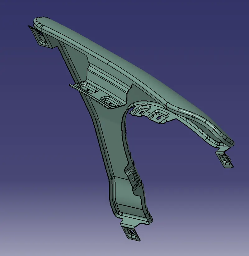
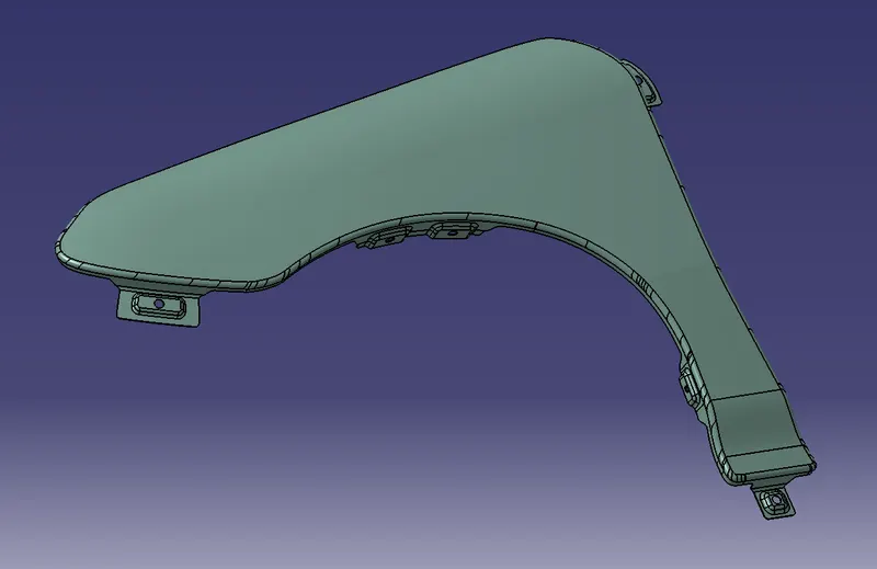
Fender Design Challenge
Aim:
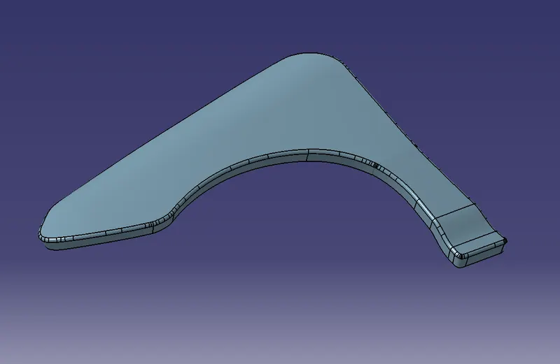
To design a front fender from the given skin data and the master section provided with Drip mounting, A-pillar, Sill, Bumper, and Cowl mountings.
Theory:
What is Fender?
A fender is a part of the automobile that is placed just above the tyres/wheels (both at the front & back). The purpose of the fender in an automobile is to prevent sand, mud, rocks, liquids, and other roads spray from being thrown into the air by the rotating tire.
Below is an example image of the front fender of a car:
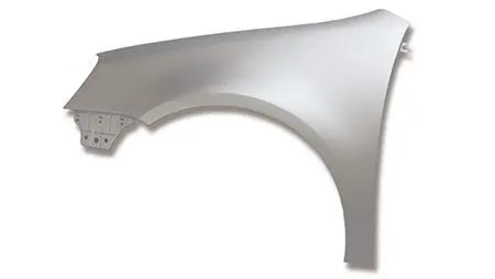
"Fender" is an American English term whereas in Britain & India it is called Wing & Mudguard respectively. The fender's openings for the wheel wells tend to be much larger than the diameter of the tire because they do not move with the tire suspension and consequently must be large enough to allow the full range of tire motion on the suspension without touching the interior of the wheel well.
Types of Fender:
There are different fender styles. While appearance may be one of the first things on a person mind when choosing a fender style, but one should also be thinking about the amount of coverage that will need to cover enough to stop water spray, rocks, and other debris from hitting your truck, trailer, and other vehicles on the road.
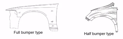
Full Fender:
A full fender means they will be covering more area of the wheel in comparison to the half fender and it also extends towards the ground a lot more. The main advantage is increased coverage, less water on you and importantly less water on your feet, meaning less road dirt and stuff stays drier longer. Since they cover more it also has the benefit of shielding your bike a bit more from that gritty wearing road dirt so your bike components will also benefit. But due to its bulky shape, the full fender increases the weight of the component which in turn increases the overall weight of the car's body
Half Fender:
As the name itself refer, the half fender will be covering only the half portion of the wheel's area while the remaining part will be covered with the bumper part. This is done to make sure the weight of the vehicle is reduced without comprising on the quality & service. Most of the modern-day vehicles come with half fender because of their rich aesthetic finish & low overall weight.
Drip:
It is the area through which the fender is attached to engine housing through fasteners. There should be some consideration followed to design the drip area of the fender. From the backside of the front fender, there will be 200mm clearance for the cowl(wiper motor) mounting area.
A-Pillar:
The roof support structure on either side of a vehicle's windshield. On a typical sedan, additional pillars are located between the front and rear doors (B pillar) and on either side of the rear window (C pillar).
Sill:
The rocker panel, or sill, is the part of the car traditionally running between the wheel-arches beneath the doors.
Bumper:
A bumper is a structure attached to or integrated with the front and rear ends of a motor vehicle, to absorb impact in a minor collision, ideally minimizing repair costs.
Cowl:
A cowl is a panel that covers the gap between your car's hood and windshield. It supports both the windshield and the dashboard while also protecting the area between the windshield and the hood.
Embosses:
Sheet metal embossing is a stamping process for producing raised or sunken designs or relief in sheet metal. This process can be made using matched male and female roller dies, or by passing a sheet or a strip of metal between rolls of the desired pattern. It is often combined with foil stamping to create a shiny, 3D effect.
Beaks:
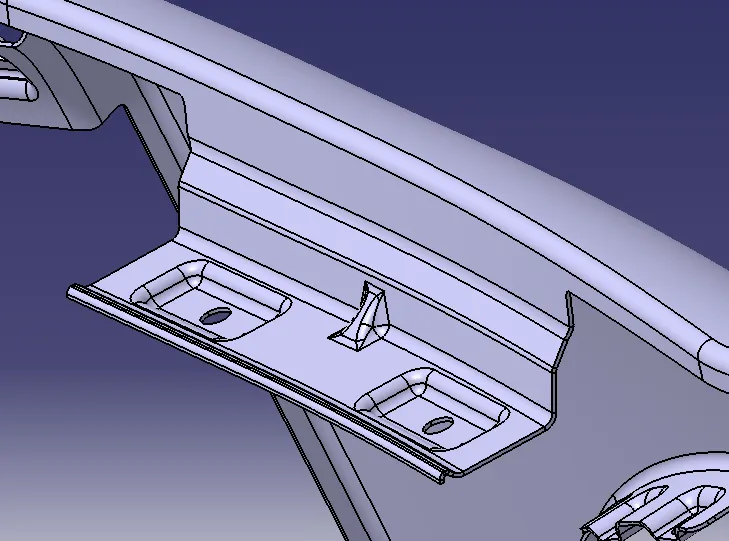
Beaks are similar to ribs which improve the strength of a bend or a flange. The beak needs to be centred on the bend it is placed on. More ribs on the same bend offer more stiffness. If two or more ribs are placed on the same bend, they need to be symmetrically placed around the centre of the bends.
Procedure:
Creating the sections:
After Opening the File, Check the model and create the mount area layouts.
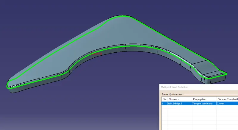
First, extract the line (refer to image) and using the parallel curve option to offset the line to 5mm.
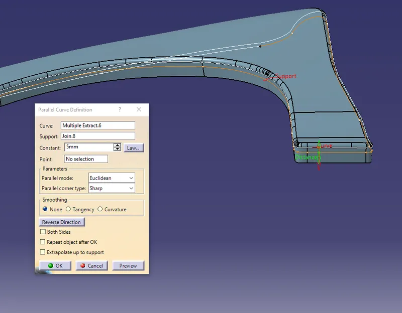
Give the shapes for all the mountings by first creating points on the offset line and the edges.
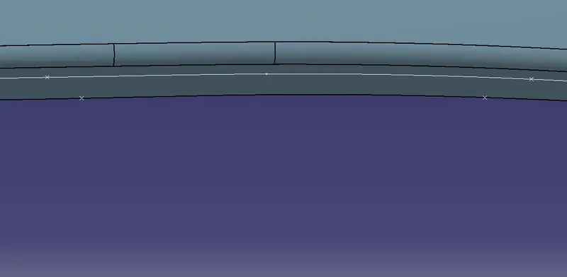
Split the offset line with the points created on it & using Connect Curve option join these points.
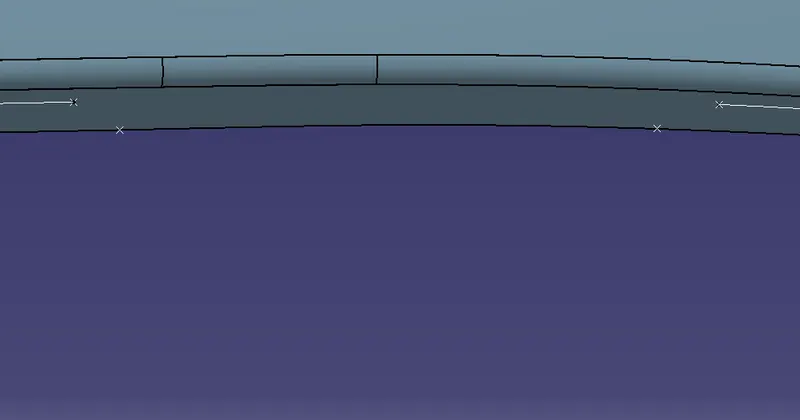
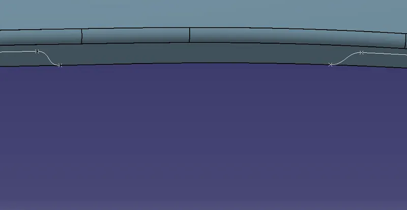
Join the offset line and the connected curves separately for every mounting.
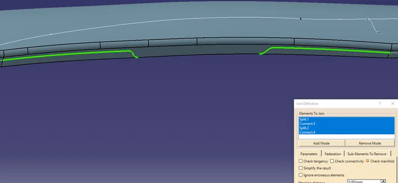
Project these lines on the surface and using the split option cut the class A surface to create a space for the mountings.
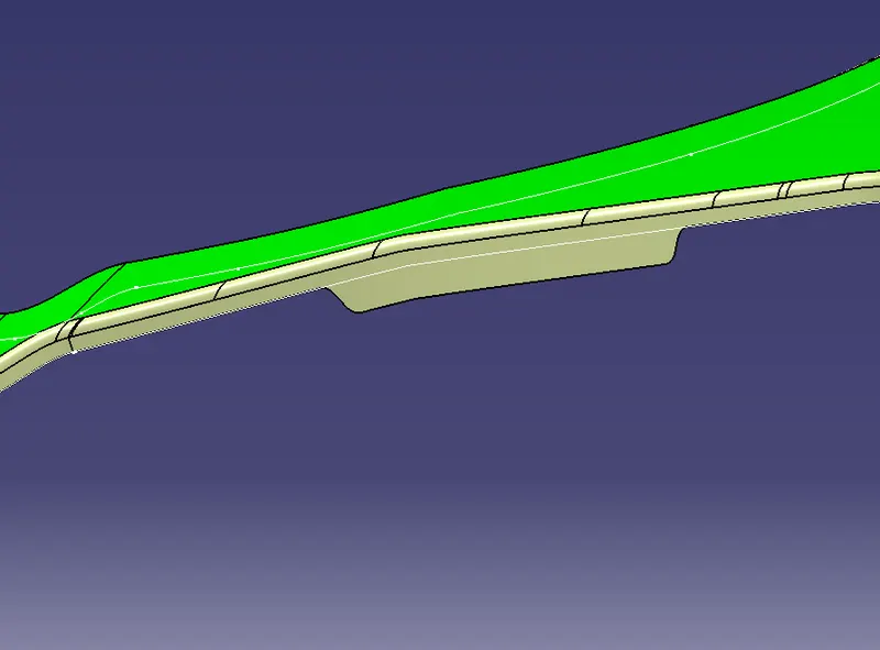
Join these split surfaces together & avoid joining the top surface as of now.
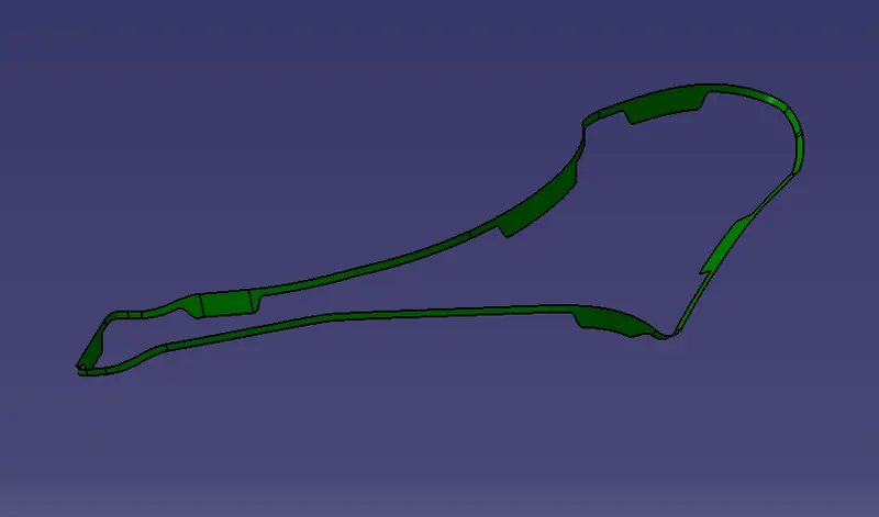
Drip Mount:
Create a straight line along the surface by using a point-point option. This line will be serving as a draft direction for creating the drip mounting.
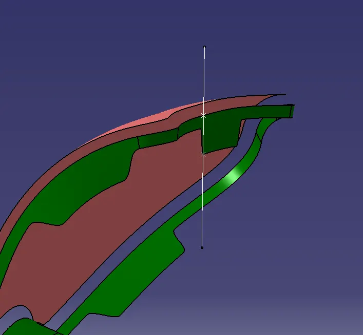
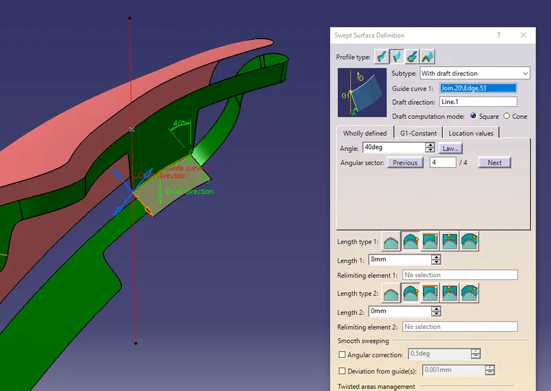
Now first sweep the edge to 40° using the draft direction as the line.
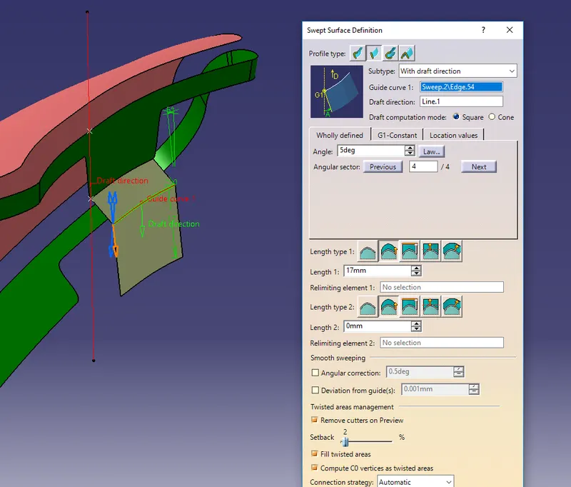
Next by selecting the edge of the previous sweep surface, sweep the edge to 17mm with a 5° draft.
Again sweep the edge of the previous surface to 25mm with a 90° draft.
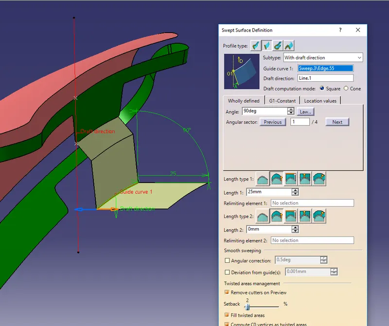
Similarly, by following the master section inputs, we have created further surfaces and joined all these surfaces together and provided the required fillets to it.
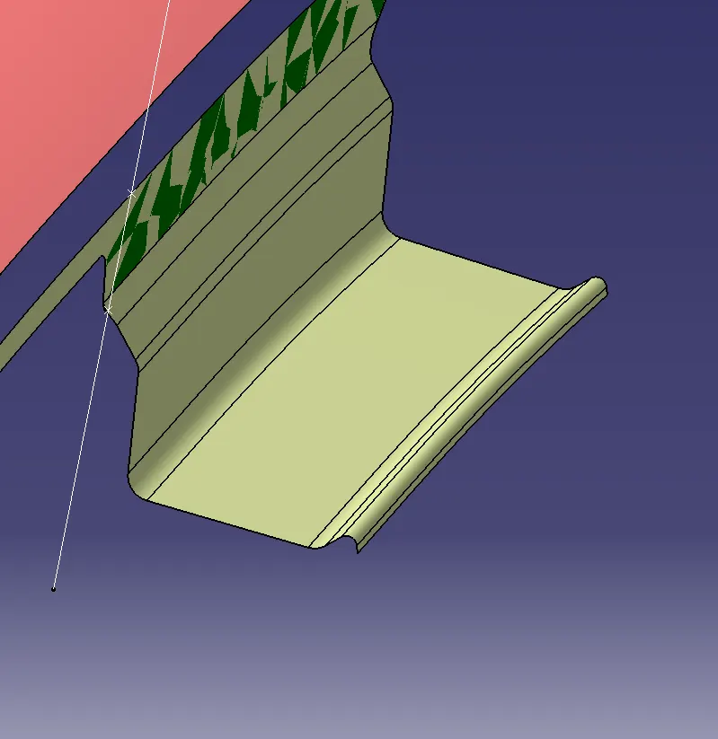
Now to create the embossments on the drip, we first need to draw a sketch & project it on the drip surface.
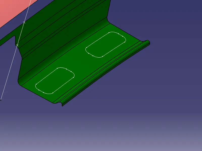
Split the drip surface using this projected sketch and sweep its edges to a certain/required height.
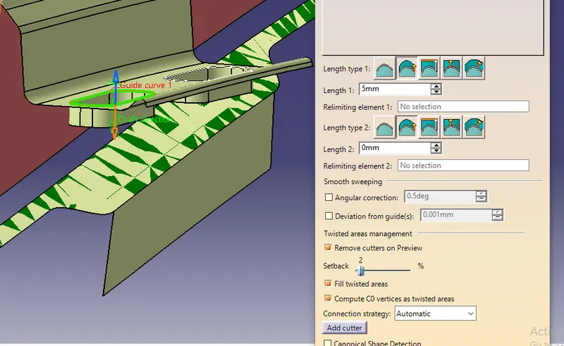
Note: I have taken 3.5mm height for the embossments and used the line (which we have created at the start) as the draft direction.
Create the top surface by offsetting the base surface to 3.5mm & trim the sweep surface with the offset surface.
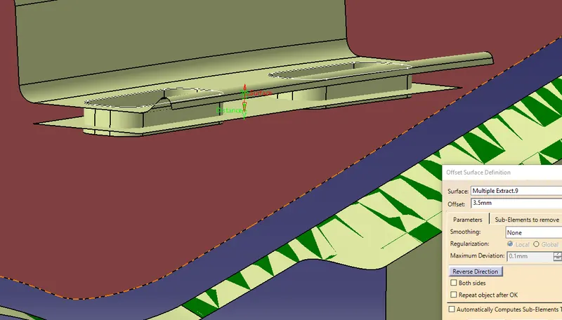
Create holes on the embossments by creating another sketch or by just simply creating a cylinder and splitting it with the surface.
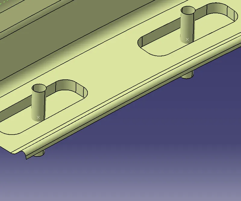
Finally, give the required fillets to all the edges and this will give us the Drip mounting.
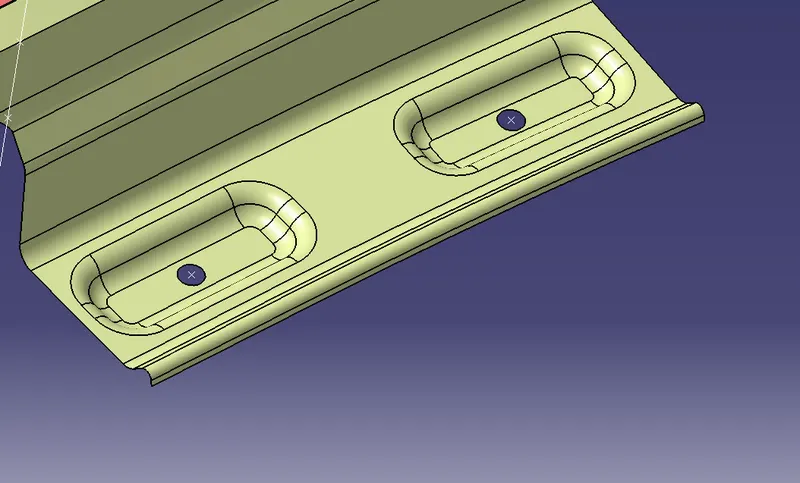
Note: We can also give beaks to improve the strength of the drip mount as shown in figure below.
Since there is no particular input is given to create other mountings, we can create the mountings following the design standards.
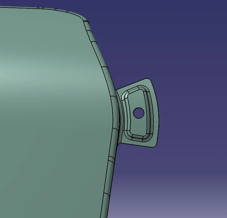
A-Pillar Mount:
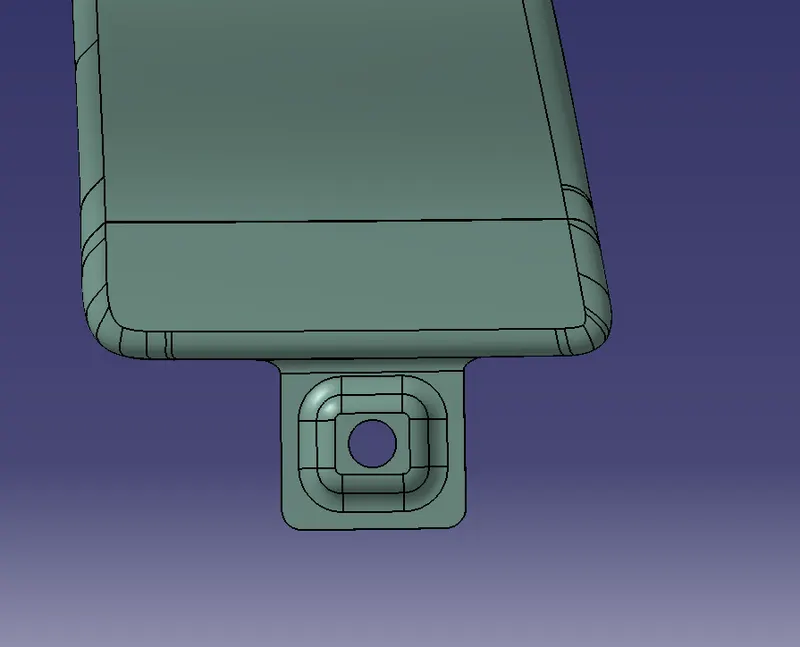
Sill Mount:
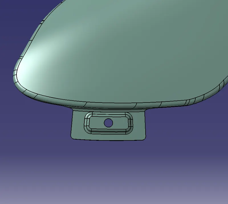
Bumper Mount:
Cowl Mount:
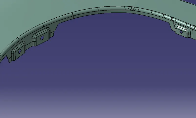
All the mountings have been created by following the similar operations performed for creating the Drip Mount.
After creating all the mounts, join all the surfaces (including the top surface) to get the final surface output of the fender.
Go to the Part workbench and use the thick surface option to create the solid with a thickness of 1mm.
Result:
Designing the Front Fender of a car with required mountings is completed successfully by following the master sections & design principles.
FINAL CAD MODEL: