Crash Tube Analysis using Radioss
BUMPER ASSEMBLY MODEL:
AIM:
To create the mesh for bumper assembly with a target element size of 6mm.
SOFTWARE:
HyperWorks 2020
USER PROFILE:
RADIOSS
PROCEDURE:
First import the model in Hypermesh (in .HM format).
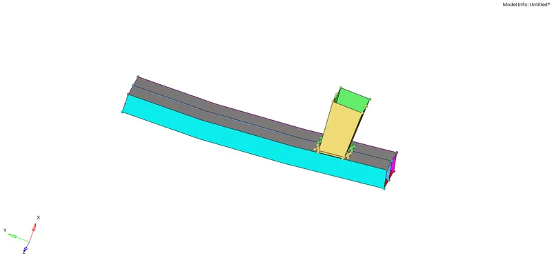
After importing the model perform geometry cleanup on the given surface.
The surfaces are not connected to each other because of the free edges. Using a “surface edit” option connects the surfaces which need to be attached.
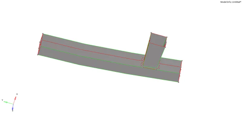
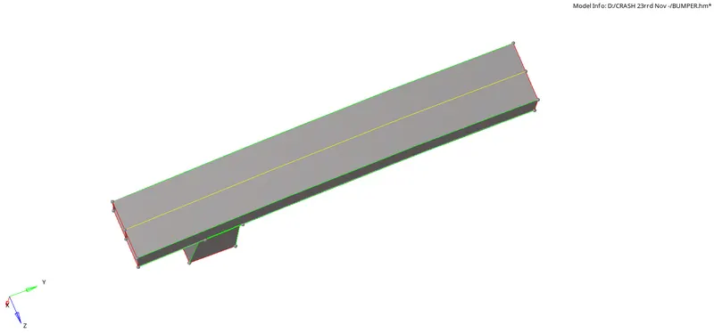
To perform the “trim with surfaces” option Go to the main menu page > Geom > surface edit > trim with surfs/plane.

Once the cleanup is done, start meshing the surfaces with a target element size of 6mm. To perform meshing Go to "main menu page > 2D > automesh > size and bias > surfaces and select mesh type as mixed, element size as 6mm and click on mesh.

After the meshing is completed, weld the upper and lower crash boxes using spot weld. To perform this operation Go to "main menu page > 2D > connectors > spot. Select the nodes and components which need to be weld. Give the tolerance value as 10 and diameter as 5mm and select the type as weld and click on create.

The below figure shows the model after spot weld.
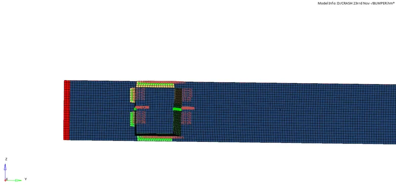
check for the edges. To check this Go to " Tool > edges > elems. Select all the displayed elements and click on find edges. If there are any edges that are disturbing the mesh connectivity then fix it by joining those elements.
Save the model in HM format.
Result:
The given component has successfully meshed with a target element size of 6mm
CRASH TUBE MODEL:
AIM:
To set up and run the simulation for all the 6 cases in HyperMesh and compare them to give a proper conclusion.
SOFTWARE:
HyperWorks 2020
USER PROFILE:
RADIOSS
PROCEDURE:
CASE 1:
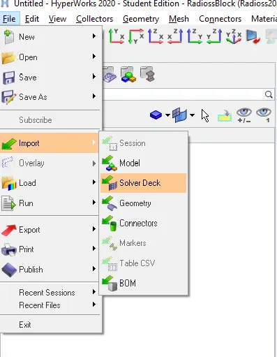
First import the starter file (.rad) in HyperMesh by going to menu bar > file > import > solver deck. Browse the file from the system and import it.
After importing the crash tube model, run the simulation as it is.
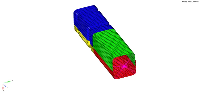
To run the simulation Go to the main menu page > Analysis > Radioss. Click on "save as" to change the file directory to case 1 folder.

Tick the box of include connectors and under the options tab, type the value as -nt 4, and click on Radioss to run the simulation.
After the simulation run is completed successfully, a message will show on the popup screen as the job is completed.
All the files which were generated during the simulation run for this case such as the .h3d file, T01 file, starter file, engine file, etc will be stored in the input file directory (case 1 folder).
CASE 2:
In case 2 we just need to change the inacti value to 6 and run the simulation in a separate folder.
To change the inacti value, Go to the model browser in Tab area > Groups > self contact option. In the edit entity bar, the inacti value is given as 0, Change this value to 6.
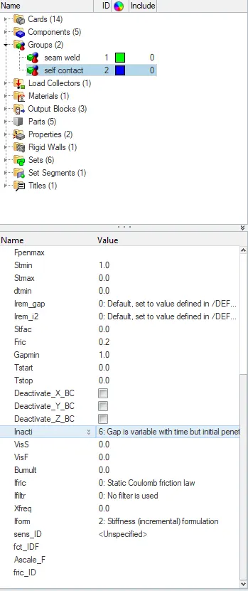
inacti:
It is the option to deactivate the stiffness. Before changing this value, it was set as 0 which means the inacti value will be set as default. But in this case, the value is set to 6 which means the gap is variable with time but initial penetration is computed.
After changing the value run the simulation and save it in a separate folder as case 2.
The procedure for running the simulation for this case is the same as mentioned in case 1.
After the simulation run is completed successfully, a message will show on the popup screen as the job is completed.
All the files which were generated during the simulation run for this case such as the .h3d file, T01 file, starter file, engine file, etc will be stored in the input file directory (case 2 folder).
CASE 3:
In case 3 we need to create a new type of contact or interface (i.e, type11) before running the simulation.
To create a new contact Go to the model browser and right-click on the Groups and create. Select the card image as TYPE 11 and give the below inputs:
Istf - 4
It is the gap for stiffness definition, it is the interface stiffness which is the maximum of the master and slave stiffness.
Igap - 1000
It is the gap option flag. The gap between the master and slave node is not defined in this case.
Idel - 0
It is the node and segment deletion flag. In this case, the value is set to zero which is a default value.
Stmin - 1
It is the minimum stiffness value that can be used only if Istf value is not equal to 1.
Stmax - 0
It is the maximum stiffness value that can be used only if Istf value is not equal to 1.
Iform - 0
It is the friction penalty formulation type. In this case, the value is set to zero which is a default value.
Fric - 0.25
It is Coulomb friction and it refers to a simple model of dry friction that is fairly accurate empirically. It is a model that helps predict the direction and magnitude of the friction force between two bodies with dry surfaces in contact.
Gapmin - 0.45
It is the minimum gap for the impact to activate.
inacti - 6
It is the option to deactivate the stiffness. Before changing this value, it was set as 0 which means the inacti value will be set as default. But in this case, the value is set to 6 which means the gap is variable with time but initial penetration is computed.
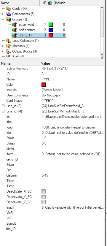
After applying all the above values run the simulation and save it in a separate folder as case 3.
The procedure for running the simulation for this case is the same as mentioned in case 1.
After the simulation run is completed successfully, a message will show on the popup screen as the job is completed.
All the files which were generated during the simulation run for this case such as the .h3d file, T01 file, starter file, engine file, etc will be stored in the input file directory (case 3 folder).
CASE 4:
In case 4, the notches need to be deleted and a plane mesh created in place of those notches before running the simulation.
To delete the notches, click F2 in order to open the delete option panel. Now select the elements (notch elements) and click on “delete entry”. The notches are now deleted from the system.
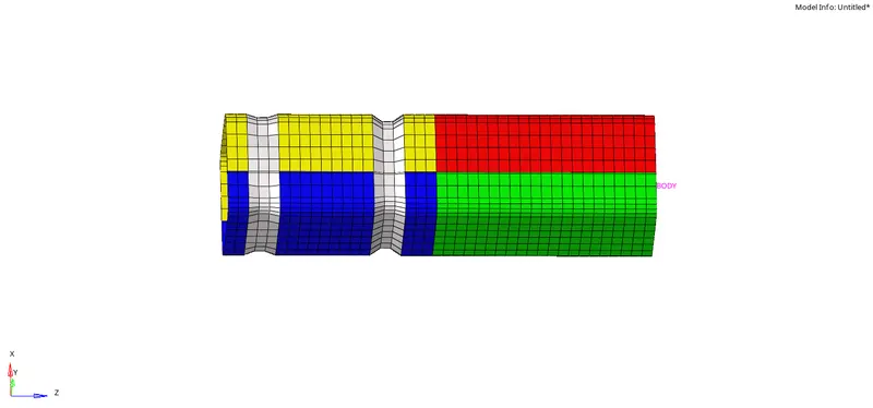
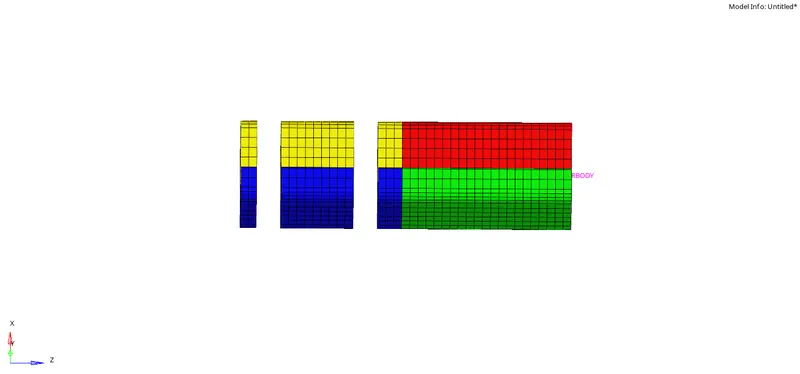
Now to create a plane surface Go to the main menu page > 2D > ruled. Select the nodes of the first path and later the second path and click on create.
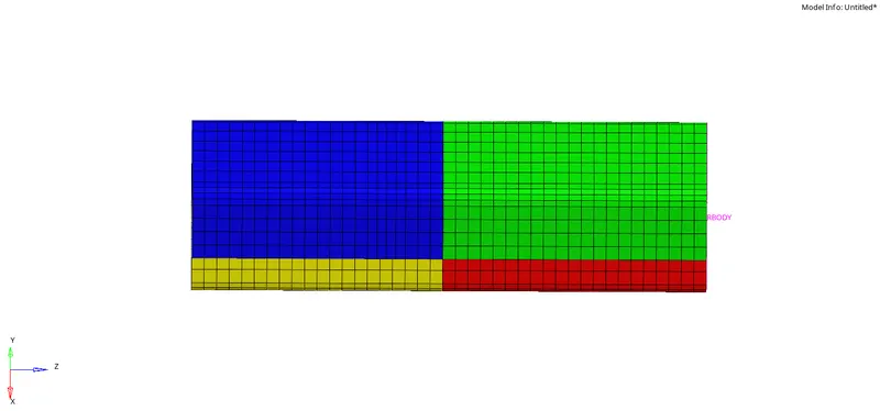
Note: Create the mesh without a surface. Select the drop-down icon on the ruled panel and choose mesh, w/o surface option.
Now delete the boundary conditions. To perform this operation Go to Tab bar > solver > BCS, right-click on the BCS entity, and delete.
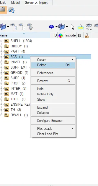
Note: To open the solver Go to the main menu bar > View > Browsers > Hypermesh > Solver.
After applying all the above-mentioned changes, run the simulation and save it in a separate folder as case 4.
The procedure for running the simulation for this case is the same as mentioned in case 1.
After the simulation run is completed successfully, a message will show on the popup screen as the job is completed.
All the files which were generated during the simulation run for this case such as .h3d file, T01 file, starter file, engine file, etc will be stored in the input file directory (case 4 folder).
CASE 5:
In case 5, a new notch needs to be created in the middle of the crash tube before running the simulation.
To create a notch, a translate option is used. To perform this operation Go to the main menu page > Tools > Translate. Select the nodes to translate, set the orientation of the elements, give magnitude as 4.094 and click on translate + or - .
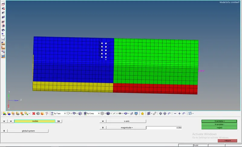
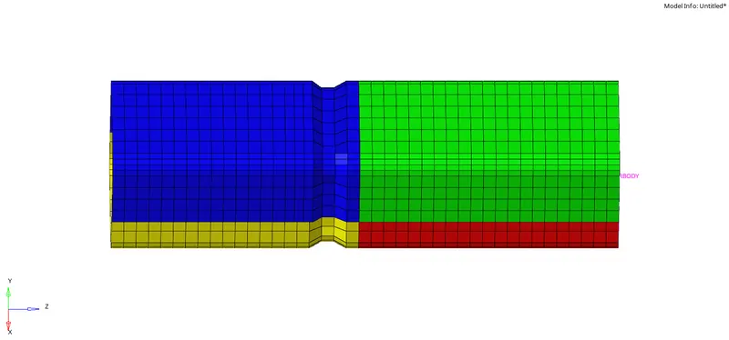
Once the notch is created, run the simulation and save it in a separate folder as case 5.
The procedure for running the simulation for this case is the same as mentioned in case 1.
After the simulation run is completed successfully, a message will show on the popup screen as the job is completed.
All the files which were generated during the simulation run for this case such as the .h3d file, T01 file, starter file, engine file, etc will be stored in the input file directory (case 5 folder).
CASE 6:
In case 6, a new notch with nodes only from opposing 2 faces needs to be created as shown in the below figure.
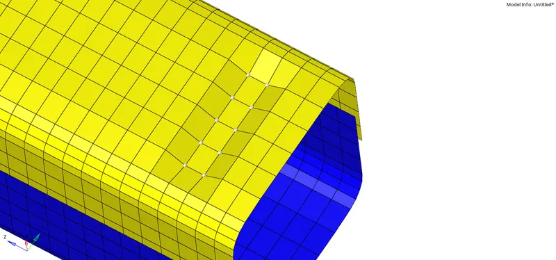
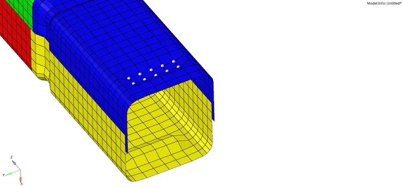
To create a notch, a translate option is used. To perform this operation Go to the main menu page > Tools > Translate. Select the nodes to translate, set the orientation of the elements, give magnitude as 4.094 and click on translate + or - .
Once the notch is created, run the simulation and save it in a separate folder as case 6.
The procedure for running the simulation for this case is the same as mentioned in case 1.
After the simulation run is completed successfully, a message will show on the popup screen as the job is completed.
All the files which were generated during the simulation run for this case such as the .h3d file, T01 file, starter file, engine file, etc will be stored in the input file directory (case 6 folder).
Animation for all the cases :
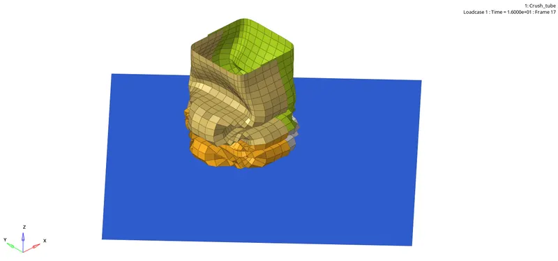
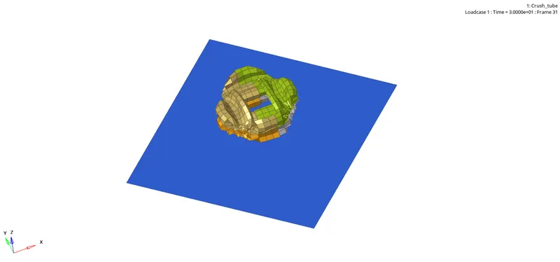
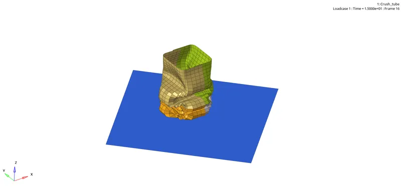
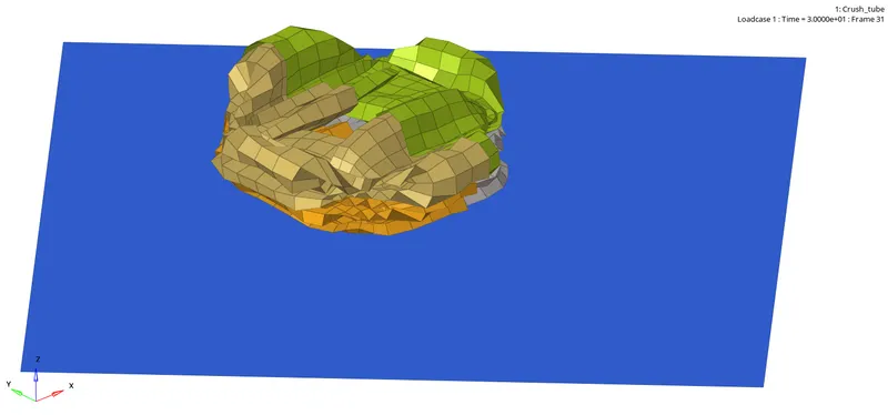
To run an animation, Go to HyperView in the client selector. Once the Hyperview is opened, Select the animation file (.h3d file) from the directory folder (new folder which we created for input file directory).

CASE 1:
CASE 2:
CASE 3:
CASE 4:
CASE 5:
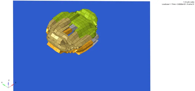
CASE 6:
Plotting graphs for all the cases:
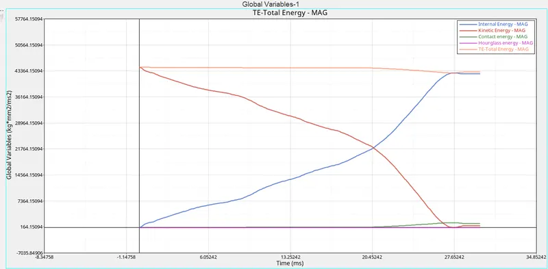
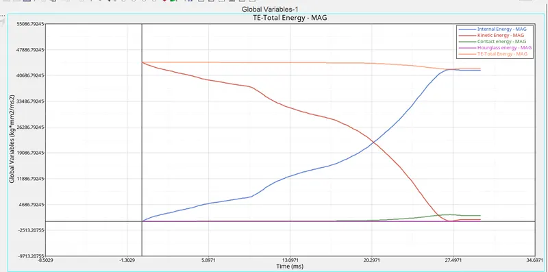
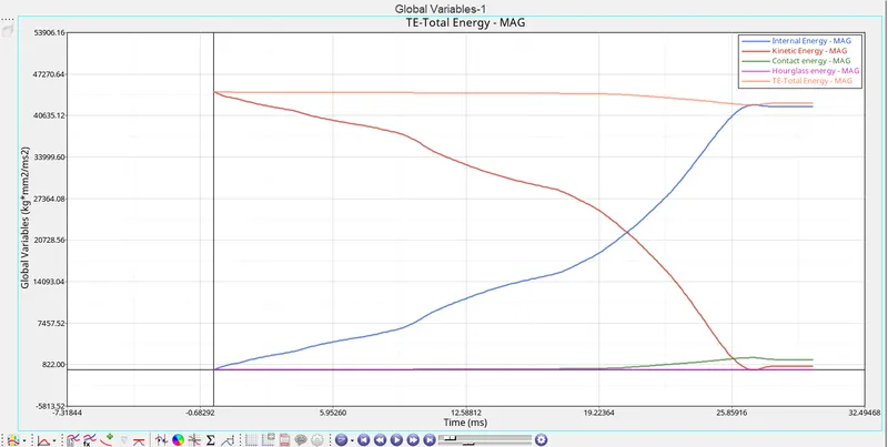
In order of internal energy, kinetic energy, hourglass energy, contact energy, and total energy. open HyperGraph2D and refer to the images below.


CASE 1:
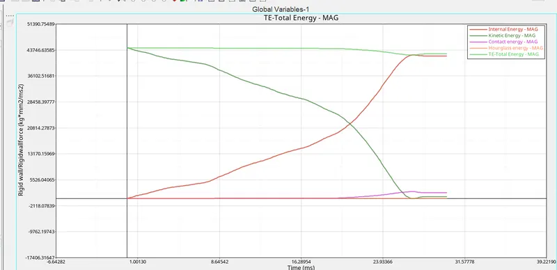
CASE 2:
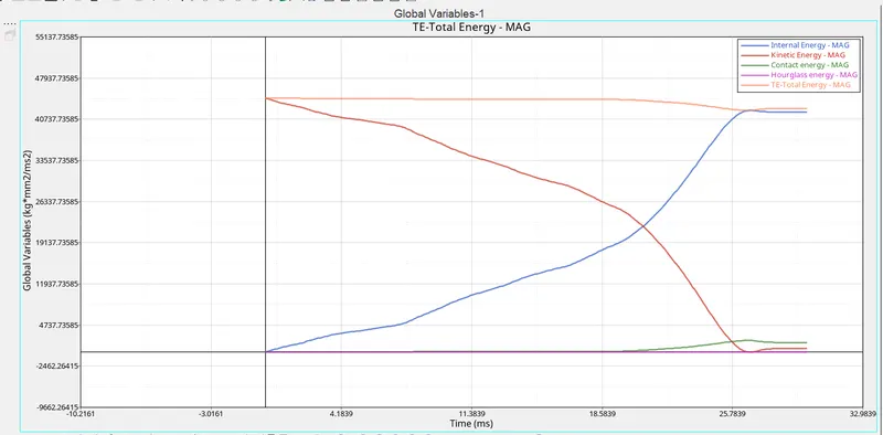
CASE 3:
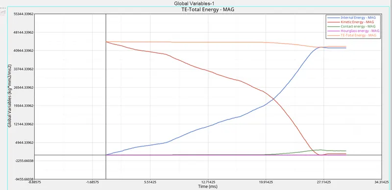
CASE 4:
CASE 5:
CASE 6:
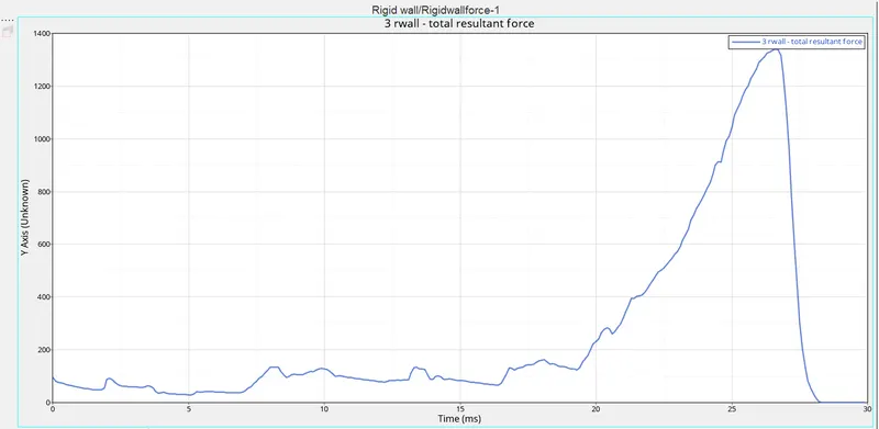
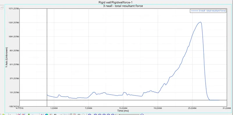
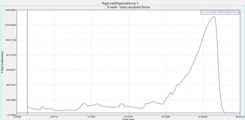
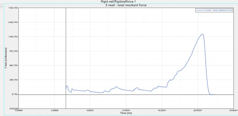
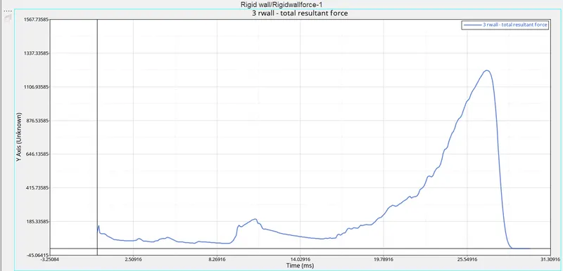
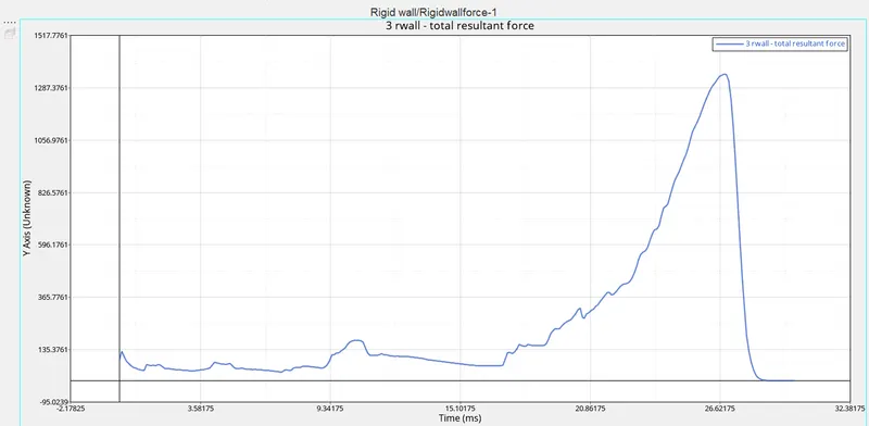
In order to plot rigid wall forces, open HyperGraph2D and refer to the image below.

CASE 1:
CASE 2:
CASE 3:
CASE 4:
CASE 5:
CASE 6:
Comparison of all cases:
After observing all the graphs for the above-mentioned cases, a few changes in the energies occurred. Some of the important points after observing the above comparison are given below.
- The area near the notch gets deformed first and then the plane surface gets deformed.
- The notches play an important role in the deformation of the crash tube.
- Due to a notch creation in case 5, there is a change in rigid wall force which can be observed from case 4 and case 5 graphs.
- Due to the change in interface type (from type 7 to type 11), the number of cycles and time steps increases in case 3 compared to case 2.
What are Type 7 and Type 11 interfaces?
Interfaces are defined to model how parts interact when they come into contact with each other. The type 7 and type 11 interfaces are discussed below.
Type 7 interface:
- Type 7 interface is a node to surface type of contact.
- stiffness is variable or non-linear
- It is a general-purpose contact and is used to simulate all conditions.
- It provides a cylindrical gap area around the edges which makes it more accurate.
- The main advantage of interface type 7 is that the stiffness is not constant and increases with the penetration preventing the node from going through the shell mid-surface.
Type 11 interface:
- Type 11 interface is an edge-to-edge type of contact.
- stiffness is variable or non-linear
- It is defined by identifying master and slave lines.
- The parameters required to define the type 11 contact are the same as type 7 with very few differences like the type 11 taking the input in the form of lines rather than nodes and surfaces.
- It is ideally used to overcome the limitations of the type 7 interface.
Reason for the change in internal energies:
Due to the notch, there is a change in internal energies. The internal energy decreases when the notch is removed in case 4 which indeed reduces the energy error as well.
How does the notch affect the results?
The notches play a very important role in the deformation of the crash tube. The notch areas have high stresses and that's the reason it deforms early when the body comes into contact in crash analysis. In the plane surfaces where the notch is removed (such as in case 4) the stress level in the body (crash tube) is low. Thus we can say that by removing the notches, the stress acting in the body can be reduced.
RESULTS:
The simulation results for all the cases have been successfully obtained and the comparison for the same is briefly discussed in the above report.