Switch Bezel Design
Aim:
To create the Switch Bezel Plastic component through the given Class-A surface and also performing draft analysis on it at the end.
Objective:
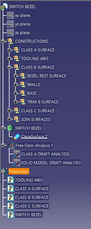
To ensure proper tree structure is followed.
Geometrical sets should have a proper name based on the sketches present inside of them.
All the sketches should be created under the geometrical set.
Using the Close Surface feature to make a solid body from the surface.
To publish the tooling axis, class A, B, and C surface.
Procedure:
TOOLING AXIS:
First import the given Class A surface model i.e, Switch Bezel in CATIA V5.
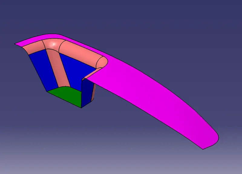
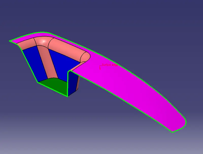
After importing the model, check for the boundaries.
Now in order to create the tooling axis in the Z - direction, first create a reference point on any surface as shown in the figure below.
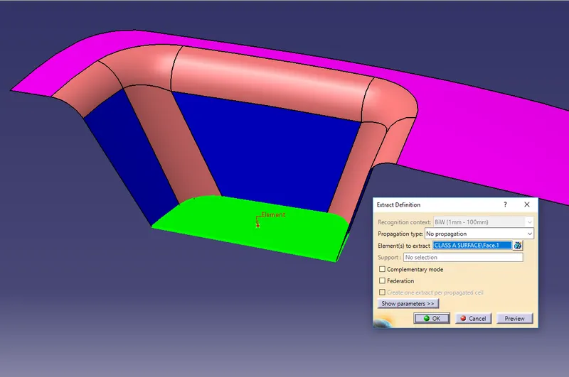
NOTE: In order to create a reference point on the surface, we first need to extract the base surface through CLASS A.
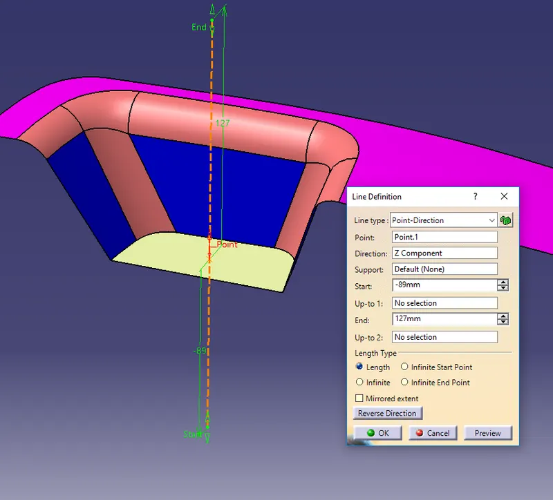
Now using the reference point, create a line in the Z - direction. This line will give us the tooling axis.
CLASS B SURFACE:
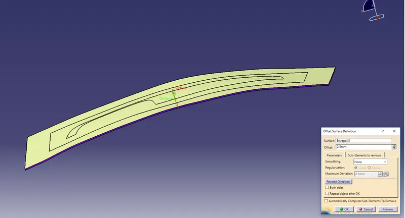
Given the thickness of the component as 2.5 mm. Now we need to create a B surface that will be similar to the A surface at an offset value of 2.5 mm.
In this operation, we are creating a “CLASS B SURFACE” in 3 different geometrical sets.
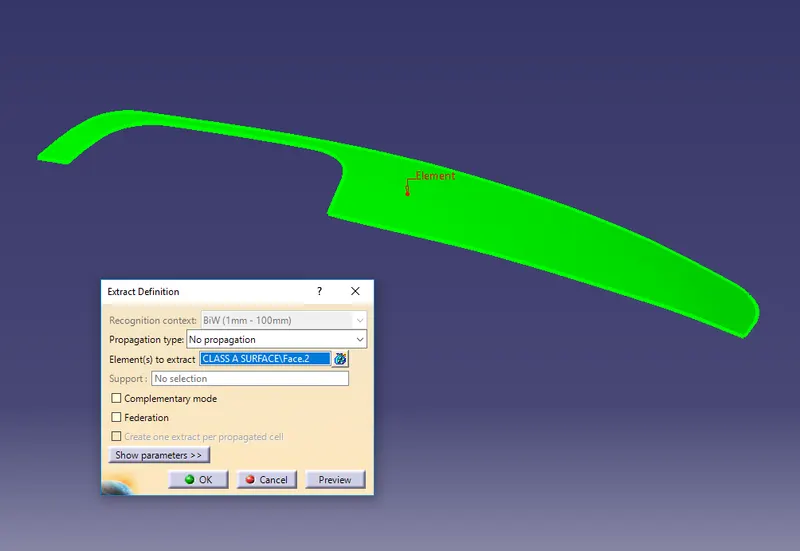
First, we are creating a “Bezel Rest Surface”. To create this surface, we need to extract the CLASS A surface as shown in the figure below.
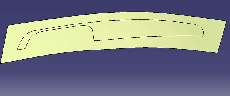
Once the surface is extracted, untrim it and then extrapolate it by a required value (any value depending on the requirement) on each side (using point continuity). Now offset it to a value of 2.5 mm.
Similarly, we need to extract the WALLS and BASE surface of the Switch Bezel in different geometrical sets and perform similar operations on it as mentioned in the above case.
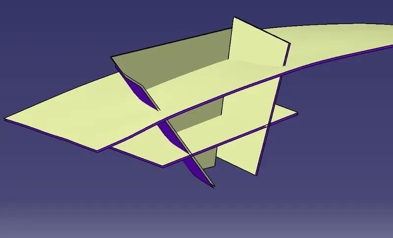
Once all the surfaces are created (i.e, Bezel Rest Surface, Walls, and Base surface), trim these surfaces to form a CLASS B surface.
NOTE: Also give the required fillets to the CLASS B SURFACE.
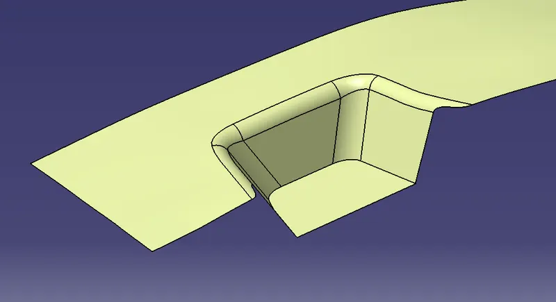
CLASS C SURFACE:
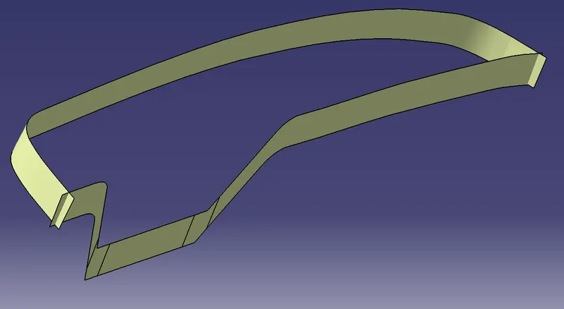
To create a CLASS C surface, first, extract the boundaries of the CLASS A surface as shown in the figure below.
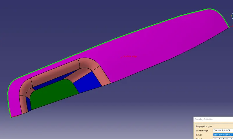
Note: The boundary of the CLASS A surface edge needs to be extracted separately and a smooth (max. Deviation as 0.001mm) operation needs to be performed on it in order to avoid the errors.
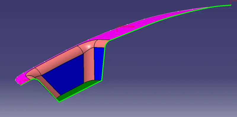
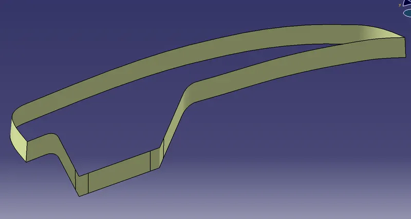
Now using the ‘sweep’ option create the surface. To perform this operation, Go to the Toolbar > Sweep > Profile type > Line > Subtype > With draft direction > Guide curve 1 - (select the extracted boundaries) > Draft direction - (select the tooling axis) > angle as 3 deg and give any suitable length and press ok.
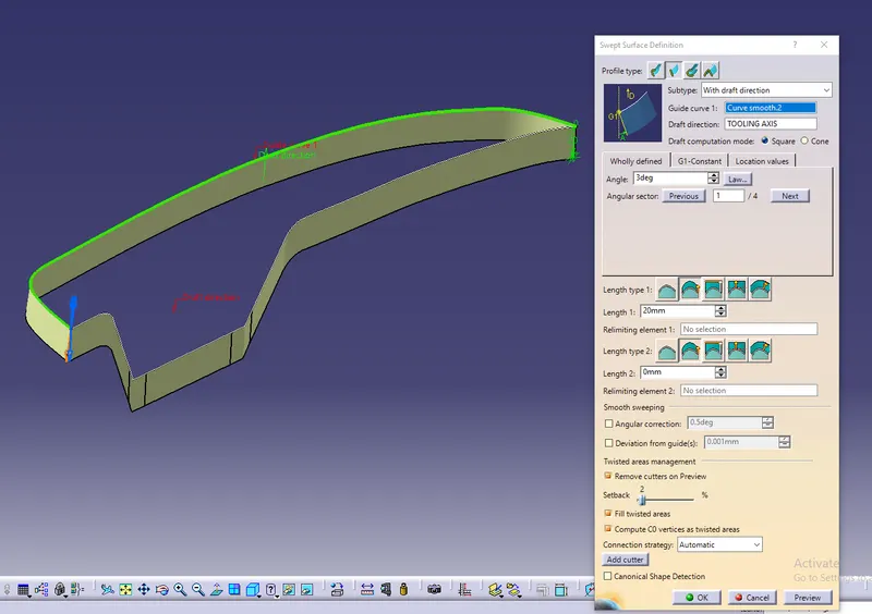
Extrapolate the surfaces and trim it to form a CLASS C surface.
JOIN SURFACES:
To create a Switch Bezel Plastic component we need to join all these surfaces (i.e, CLASS A, B, and C surfaces).
First, join the CLASS A surface with the CLASS C surface and then trim this joined surface with the CLASS B surface to get the final output.
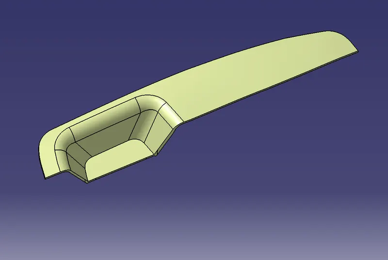
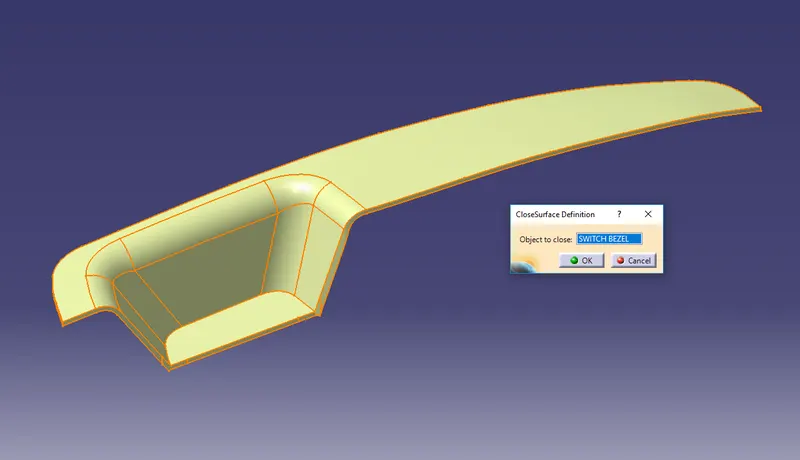
Now using the “CLOSE SURFACE” option in PART WORKBENCH, a solid body from the surface can be formed.
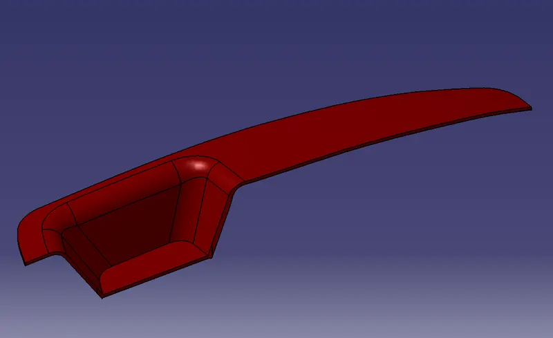
DRAFT ANALYSIS:
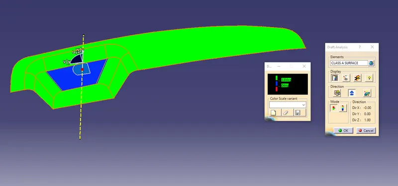
To perform Draft Analysis on the model, Go to the menu bar > select insert > Analysis > Feature Draft Analysis.
To give draft direction, use the compass and align it with the tooling axis which we created for the model. Once it is properly aligned, select the surface of the model which will show us the draft angle given on the component. Make sure the draft angle on the component is having a 3 deg draft value (component showing green in color). If the draft value is negative (component color in red) then we need to adjust the tooling axis direction with the help of a compass.
CLASS A DRAFT ANALYSIS:
SOLID MODEL DRAFT ANALYSIS:
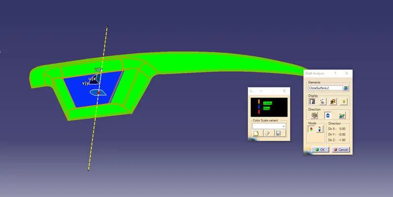
Note: Draft value ranging from 0 - 3 deg will show the component Blue in color.
Using the Analysis option under Display Tab, we can check/analyze the exact draft value at any point on the given model.
By selecting the Tooling Axis, Class A, B, and C surface (in order), publish it by going to menu bar > Tools > Publication. It will be published under the publication tab in a Tree structure.
PHRASES USED:
DRAFT:
Drafts are defined on molded parts to make them easier to remove from molds.
The characteristic elements are:
Pulling direction: This direction corresponds to the reference from which the draft faces are defined.
Draft angle: This is the angle that the draft faces make with the pulling direction. This angle may be defined for each face.
Parting element: This plane, face, or surface cuts the part in two and each portion is drafted according to its previously defined direction.
Neutral element: This element defines a neutral curve on which the drafted face will lie. This element will remain the same during the draft. The neutral element and parting element may be the same element.
DRAFT ANALYSIS:
The Draft Analysis command enables you to detect if the part you drafted will be easily removed. This type of analysis is performed based on color ranges identifying zones on the analyzed element where the deviation from the draft direction at any point, corresponds to specified values.
TOOLING AXIS:
The Definition tab on the Tool Axis dialog controls how you want the tool to orient itself whilst cutting a multi-axis toolpath. Tool axis - Select to define the tool orientation. The default value is Vertical, which is used for standard 3-axis machining. However, it can also be a fixed angle or a continuously changing orientation.
CLASS A SURFACE:
CLASS A surfaces are those aesthetic/ free form surfaces, which are visible to us (interior/exterior), having an optimal aesthetic shape and high surface quality. We all understand that today's products are not only designed considering the functionality but special considerations are given to its form/aesthetics which can bring a desire in one's mind to own that product. Which is only possible with the high-class finish and good forms. This is the reason why in design industries Class A surfaces are given more importance.
CLASS B SURFACE:
CLASS B Surfaces need to be created according to a class-A surface having all features such as Rib, boss, snap, etc) in B-side surface only. CLASS B Surface mostly doesn't have textures.
CLASS C SURFACE:
Class C surfaces are the backside surfaces that can have tool marks, flash, and other imperfections without hurting appearance, function, etc.
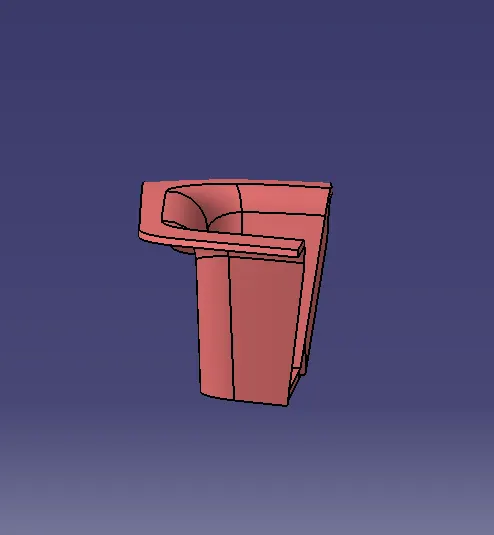
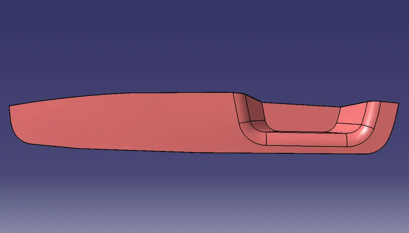
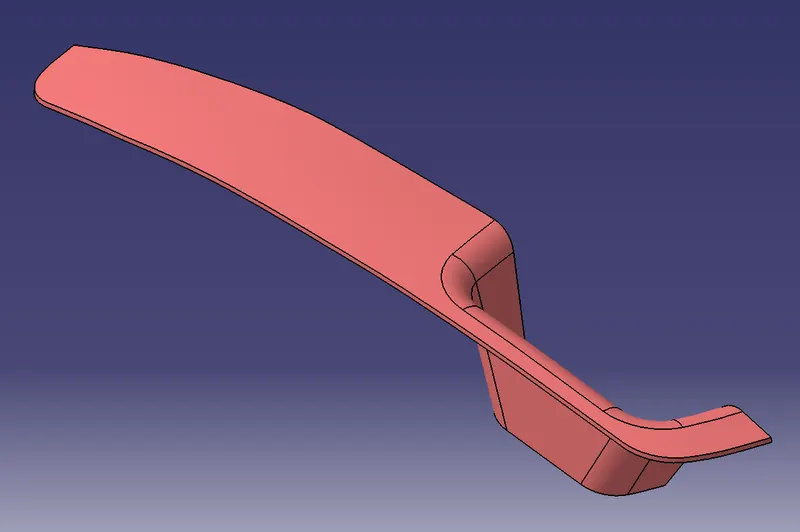
3D CAD MODEL:
FRONT VIEW:
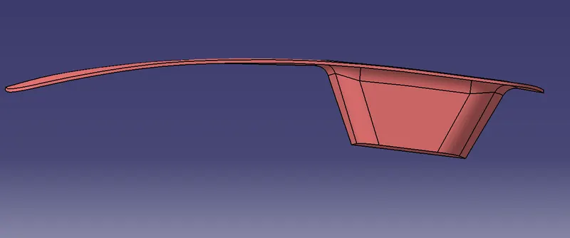
SIDE VIEW:
TOP VIEW:
ISOMETRIC VIEW:
TREE STRUCTURE:
Result:
Switch Bezel Plastic component using CLASS A surface have been successfully created and draft analysis has also been performed for the same.