1D elements on a Parallel Bracket
Aim:
To create 1D elements on a Parallel Bracket (given component/model) with a given cross-section and DOF.
Procedure:
Initially import the model in Hypermesh by selecting file type as "IGES".
Once the model is imported, create mid-surfaces of the component as "Bracket B1 and Bracket B2".
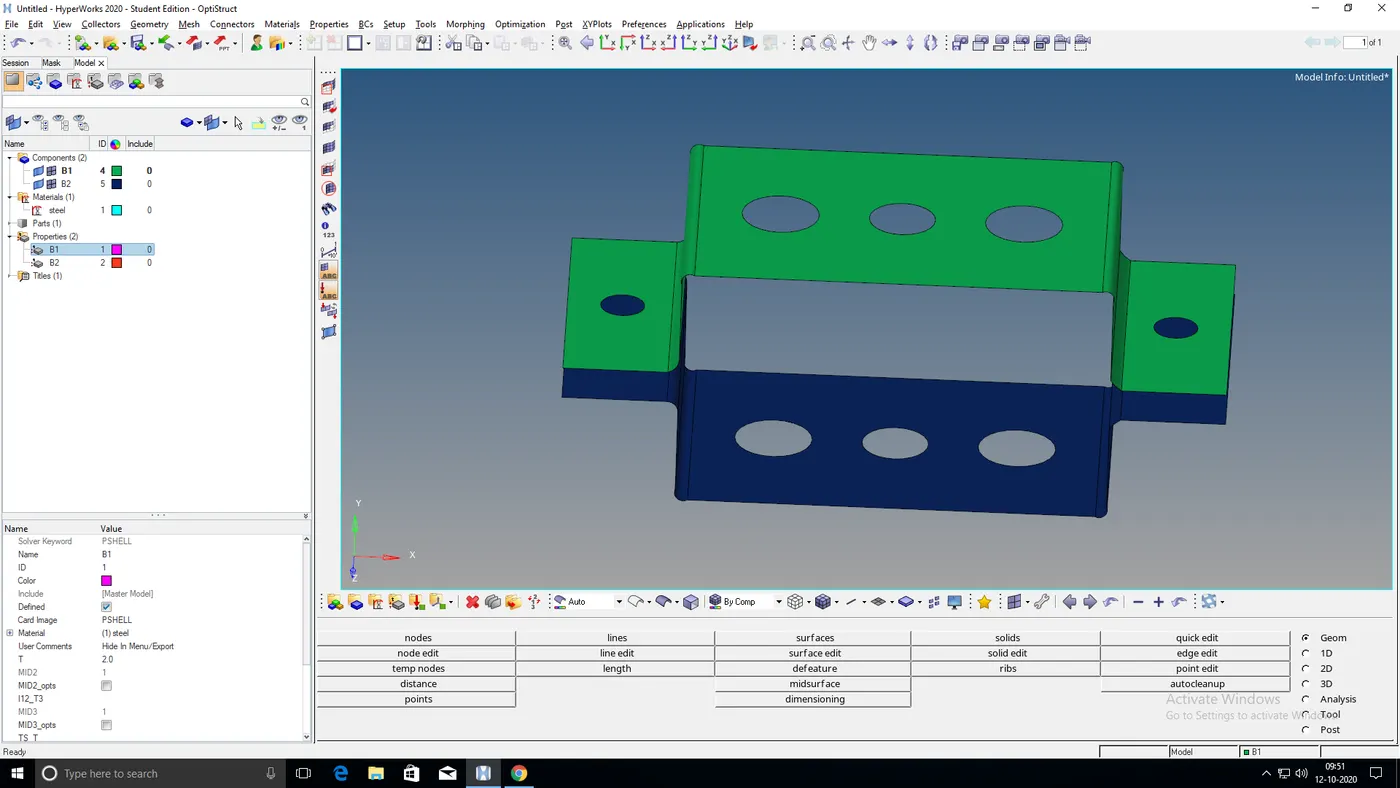
Fig: Bracket B1 and B2 (Mid surfaces) created
After creating mid-surfaces of the component, delete the solids of the parallel bracket.
Now assign properties to the brackets B1 and B2 with a thickness of 2 and 2.5mm respectively and select card image as PSHELL.
Before meshing the mid-surfaces, give a washer split with an offset value of 5mm.
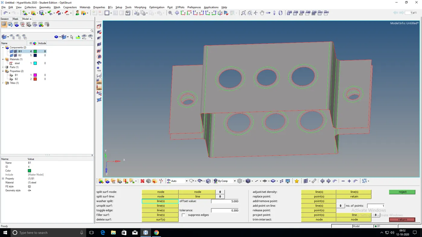
Fig: Washersplit img1
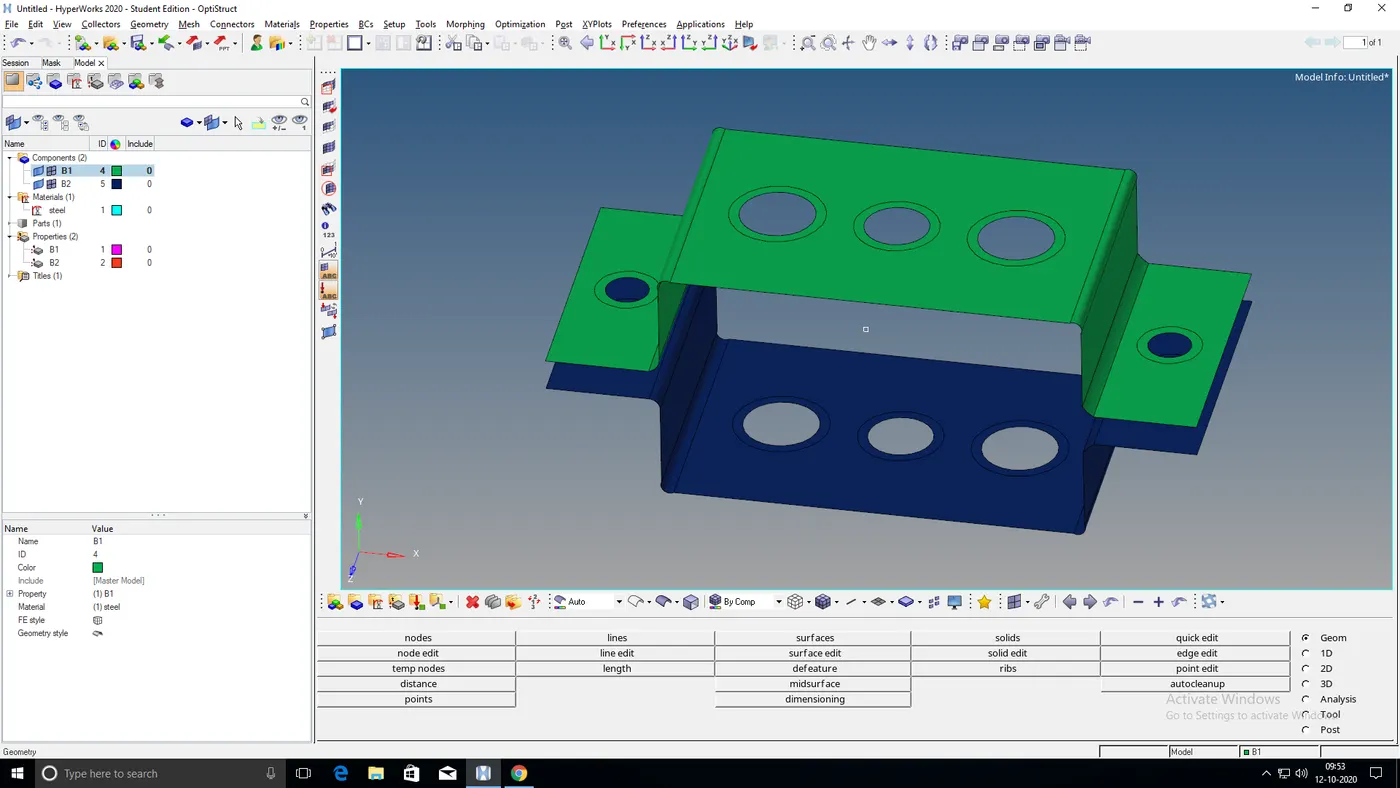
Fig: Washersplit img2
Now mesh the surfaces with an element size of 5mm and select the mesh type as 'quads'.
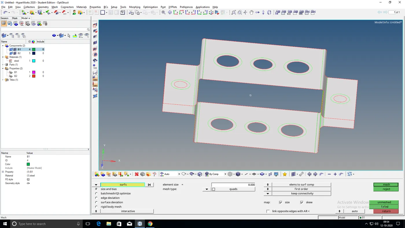
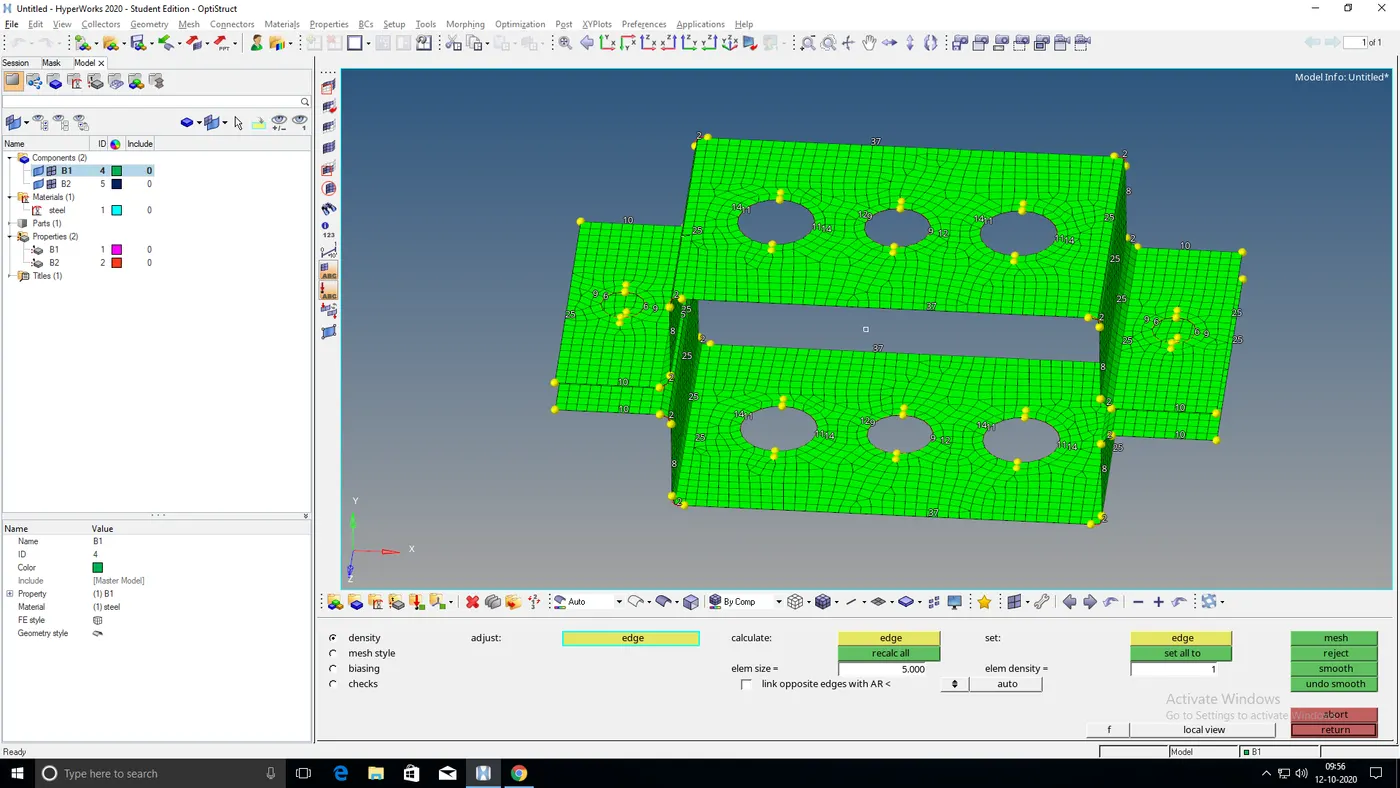
Fig: Surfaces selected for meshing Fig: Meshing with an element size of 5mm
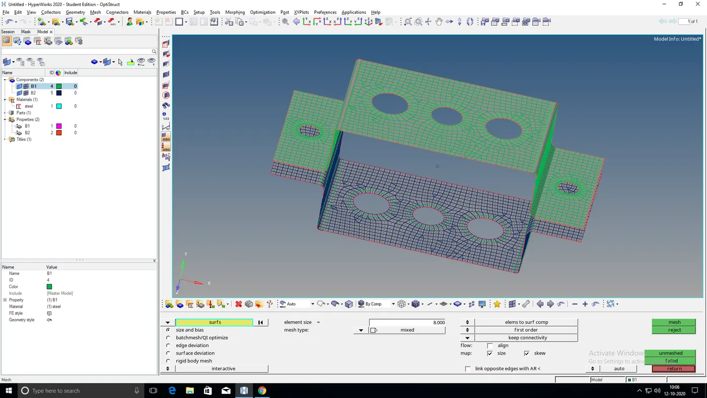
Fig: Surfaces are meshed
After meshing the surfaces, create an RBE2 link at 'a' with only translational DOF. similarly, create 2 more RBE2 links at 'd' and 'e' for applying the mass of magnitude 10.
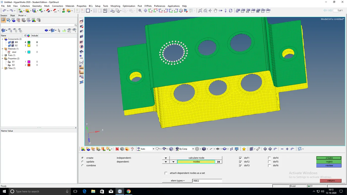
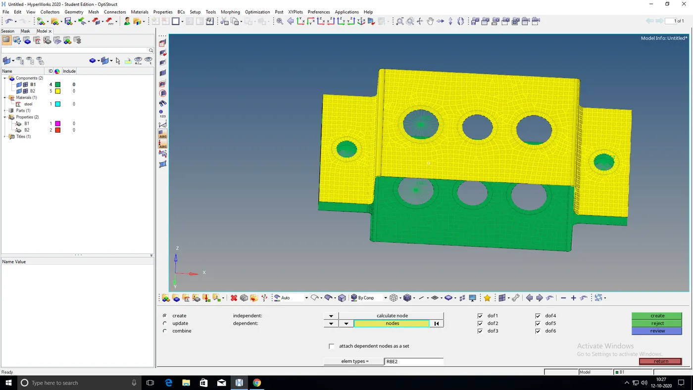
Fig: Creating RBE2 link at 'a' Fig: RBE2 link created at 'a' 'd' and 'e'
At 'b', create an RBE3 link with all DOF and similarly also create an RBE3 link at 'c' but here with only DOF in x and y.
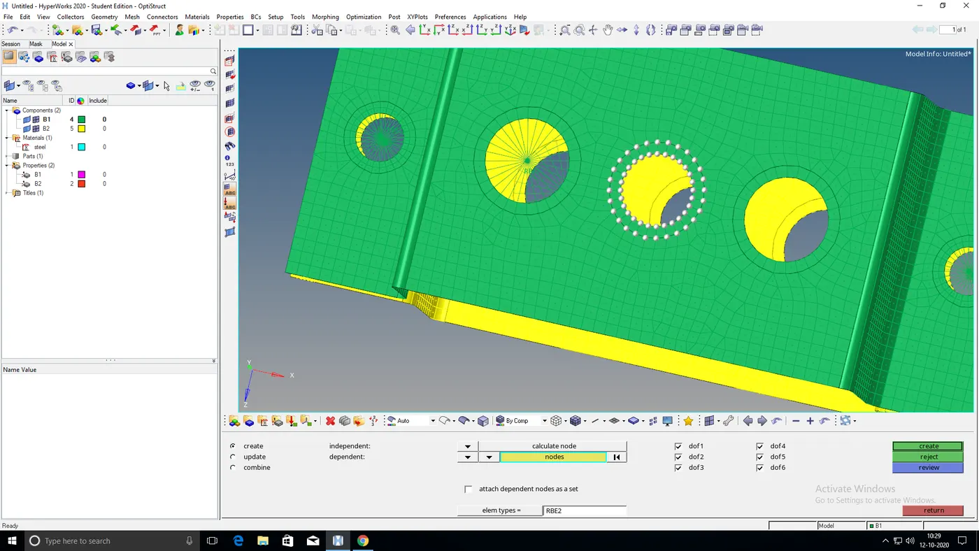
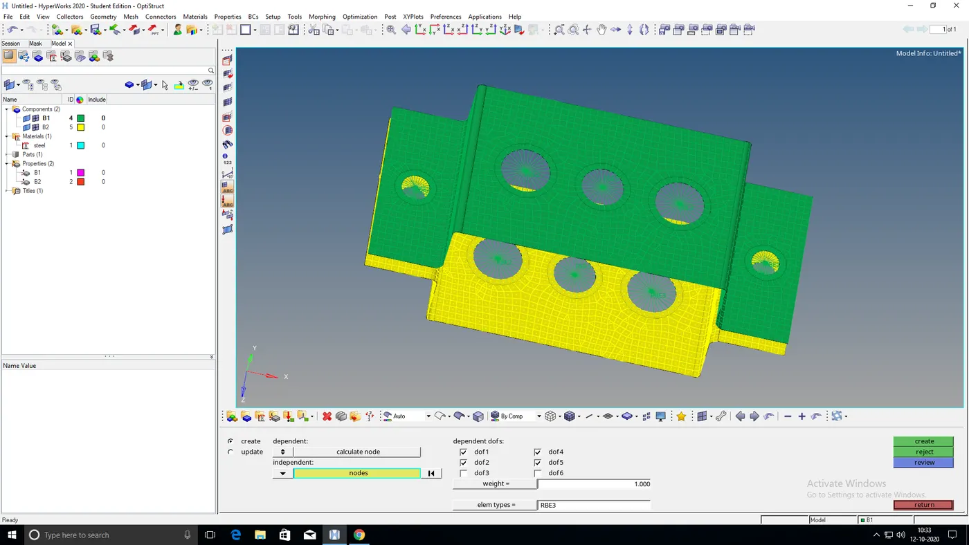
Fig: Creating RBE3 link at 'b' Fig: RBE3 link created at 'b' and 'c'
Go to the 'Hyperbeam' tool in order to create the cross-sections and give dimensions to them.
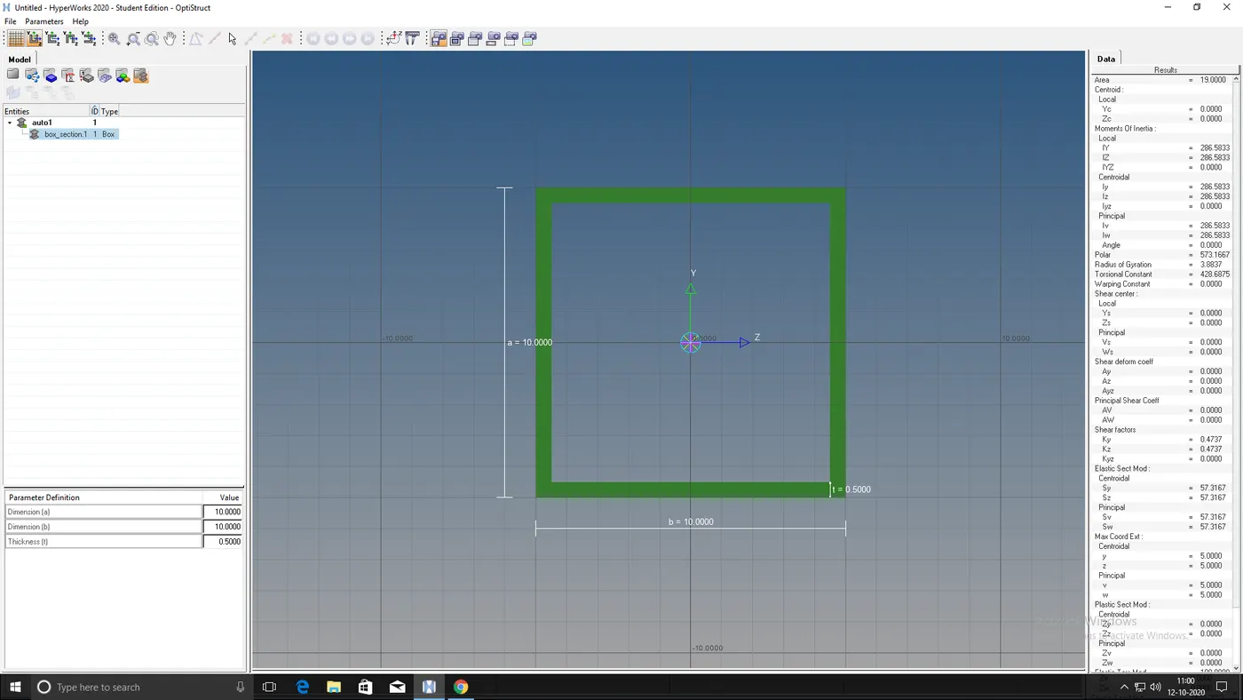
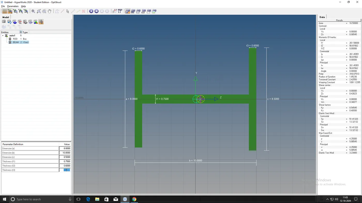
Fig: BOX CROSS-SECTION Fig: I CROSS-SECTION
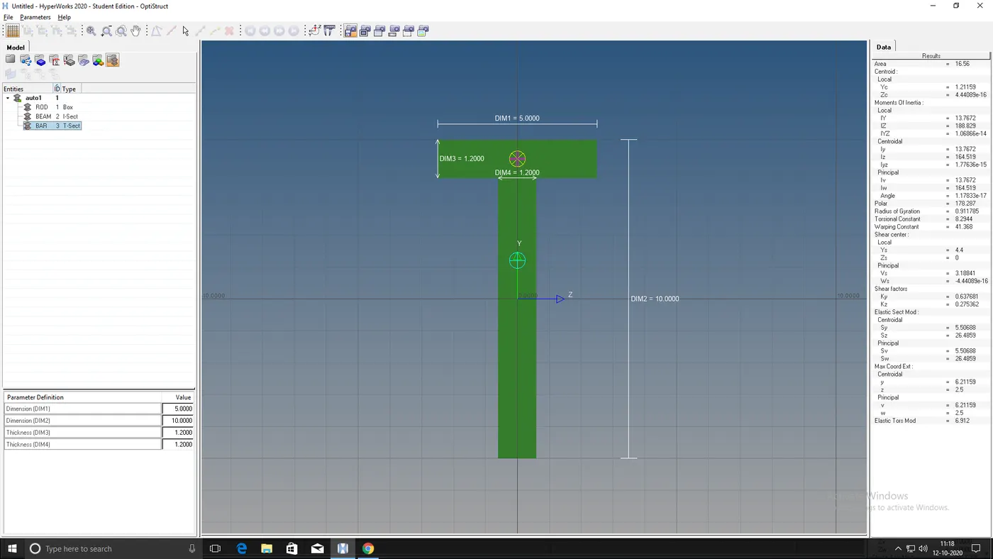
Fig: T CROSS-SECTION
Now create a rod, beam and bar at a,b and c respectively.
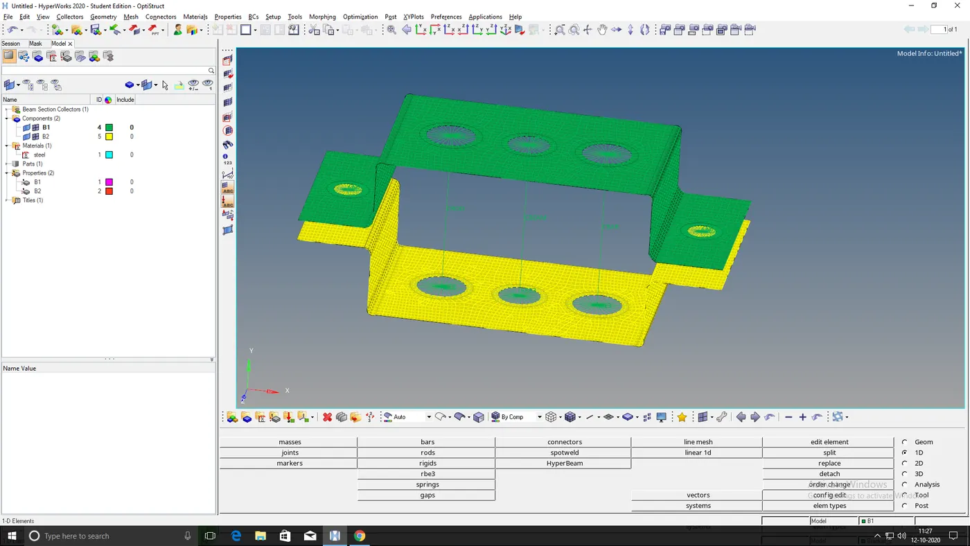
Fig: ROD, BEAM, AND BAR at a,b and c respectively
Once these elements are created, update the properties in order to give the cross-sections to it.
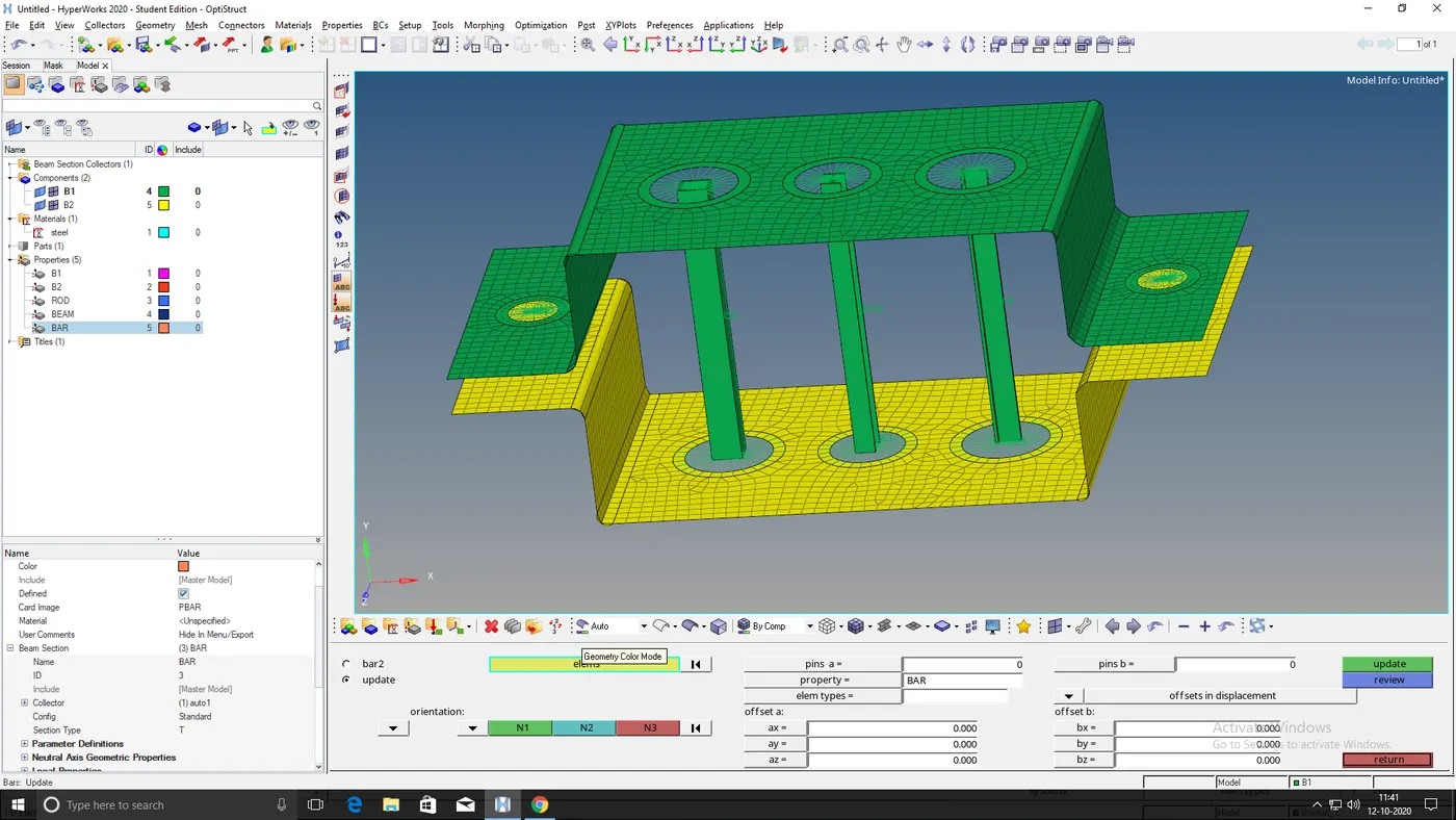
Fig: CROSS SECTIONS OF BOX, I AND T as ROD,BEAM AND BAR
Apply a mass of magnitude 10 at 'd' and 'e'.
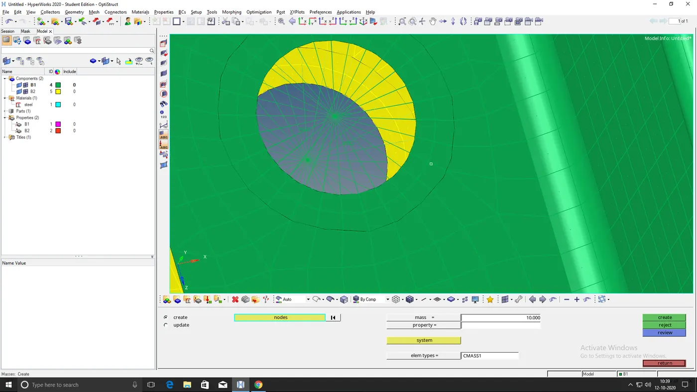
Fig: Mass of magnitude 10
With the help of spring element join the two components i.e, bracket B1 and B2 at 'f'.
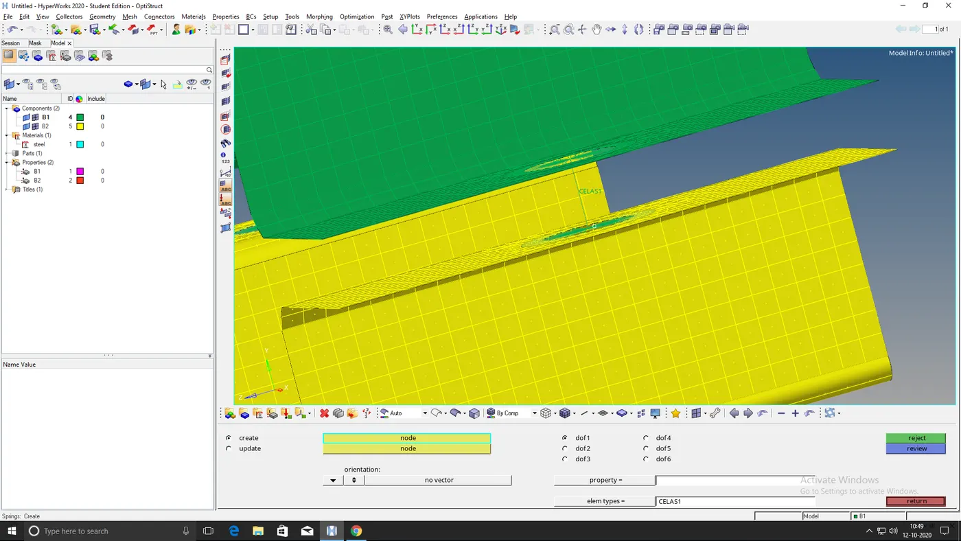
Fig: Spring element joining 2 components
Final output:
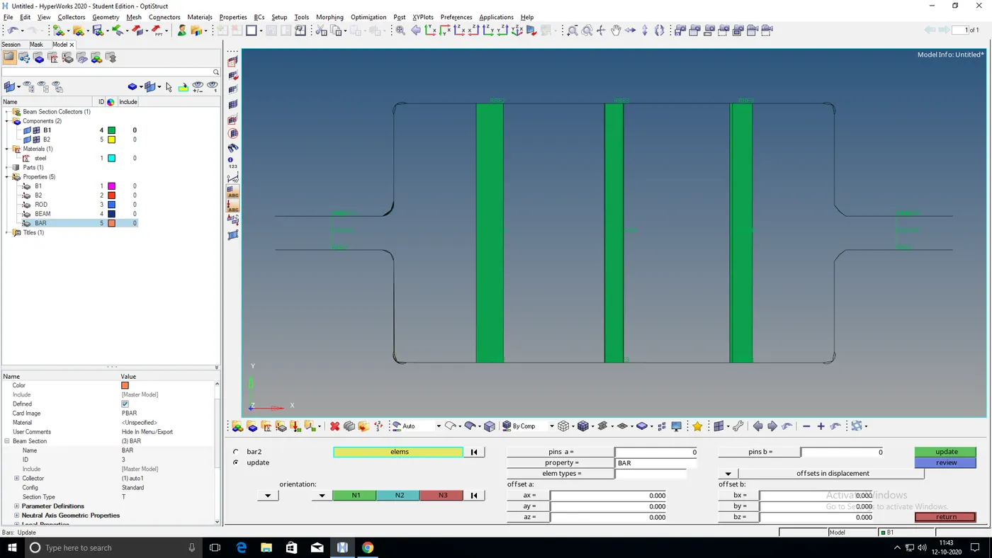
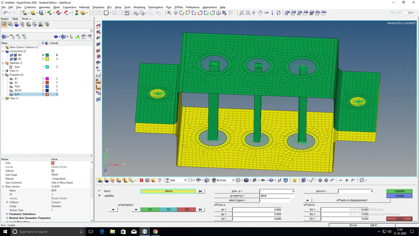
Fig: Final output img1 Fig: Final output img2
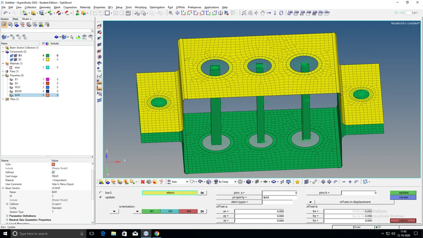
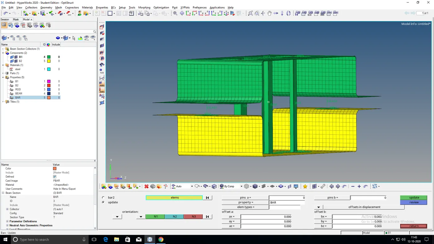
Fig: Final output img3 Fig: Final output img4
Result:
Thus we were successfully able to generate the mesh on the mid surface and create 1D elements on the given component with given cross-section values.