Door Applique Design with Engineering Features
Aim:
To design the Door Applique with engineering features such as Heat stakes and Locators, given styling surface / CLASS A surface as input and also to perform Draft Analysis on the final 3D CAD model.
Objective:
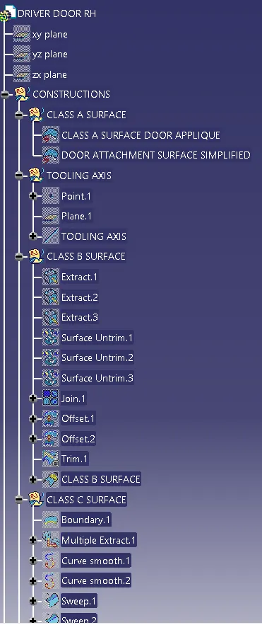
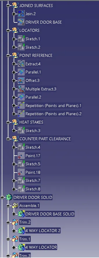
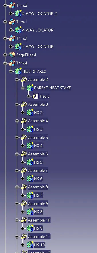
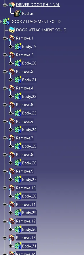
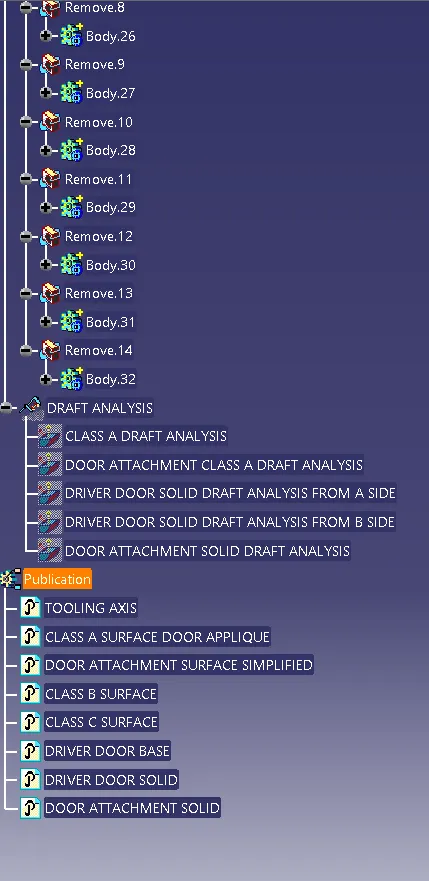
To ensure proper tree structure is followed.
Geometrical sets should have a proper name based on the sketches present inside of it.
All the sketches should be created under the geometrical set.
Using the Close Surface feature to make a solid body from the surface.
To publish the tooling axis, class A, B and C surface.
Procedure:
TOOLING AXIS:
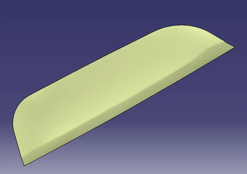
First import the given Class A surface model of the Door Applique in CATIA V5.
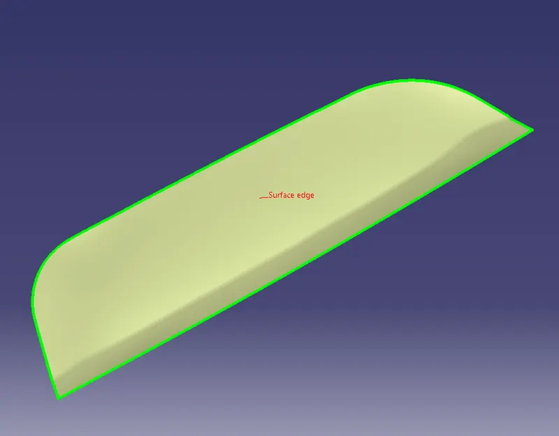
After importing the model, check for the boundaries.
A tooling axis needs to be created in a direction from which it can capture most parts/features of the component. Generally a tooling axis will be created perpendicular to the base surface of the component.
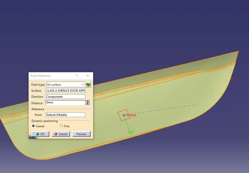
In this case we need to create the tooling axis in Y - direction. So in order to create the tooling axis in Y - direction, we first need to create a reference point on the center of the base surface as shown in the figure below.
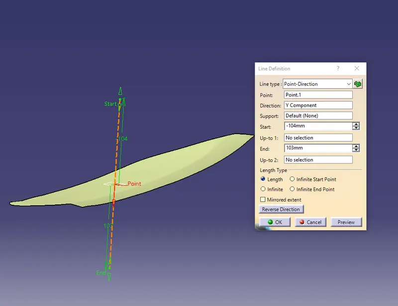
Now using the reference point, create a line in Y - direction. This line will give us the tooling axis.
DRAFT ANALYSIS ON CLASS A SURFACE:
To perform Draft Analysis on the CLASS A surface, Go to menu bar > select insert > Analysis > Feature Draft Analysis.
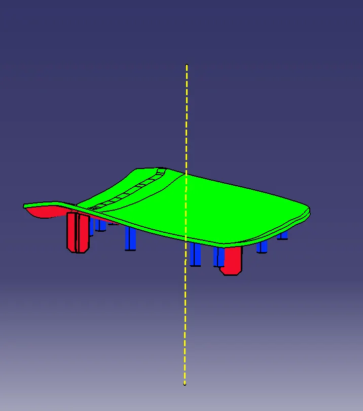
To give draft direction, use the compass and align it with the tooling axis which we created for the model. Once it is properly aligned, select the surface of the model which will show us the draft angle given on the component. Make sure the draft angle on the component is having 3 deg draft value (component showing green in colour). If the draft value is negative (component colour in red) then we need to adjust the tooling axis direction with the help of compass.
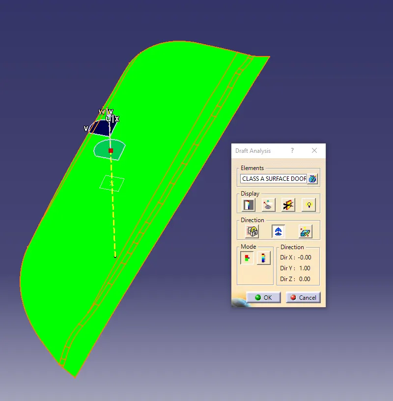
Using the Analysis option under Display Tab, we can check / analyze the exact draft value at any point on the given model.
CLASS B SURFACE:
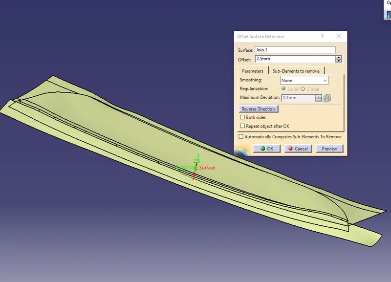
Considering the thickness of the component as 2.5 mm, we need to create a CLASS B surface which will be similar to the A surface at an offset value of 2.5 mm.
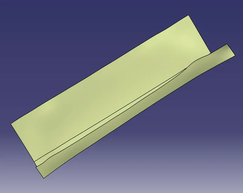
A “CLASS B” surface can be created by first extracting the base of a CLASS A surface. This extracted surface is then untrimmed followed by the extrapolation of the untrimmed surface.
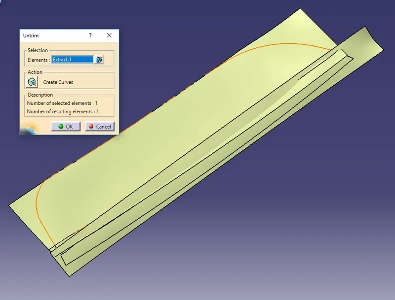
NOTE: The surface needs to be extrapolated by any suitable value such that it must bisects / intersect with the CLASS C surface. This extrapolation of surface will allow us to easily trim the surface to get a final output.
Once the surface is created we can offset it by a value of 2.5mm (thickness of the component). This will give us a CLASS B surface.
CLASS C SURFACE:
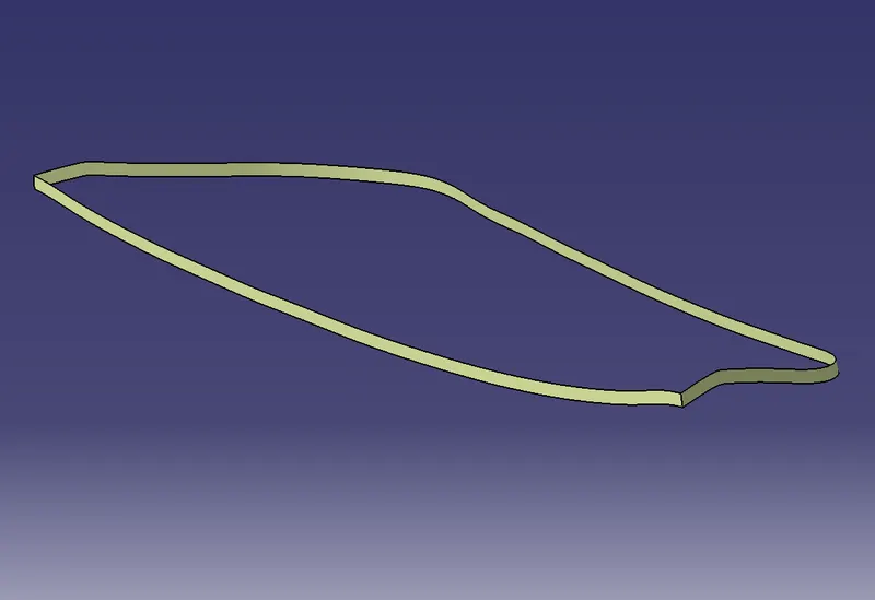
To create a CLASS C surface, first extract the boundaries of the CLASS A surface as shown in below figure.
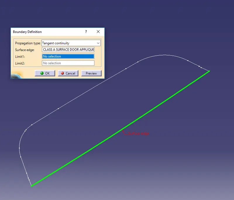
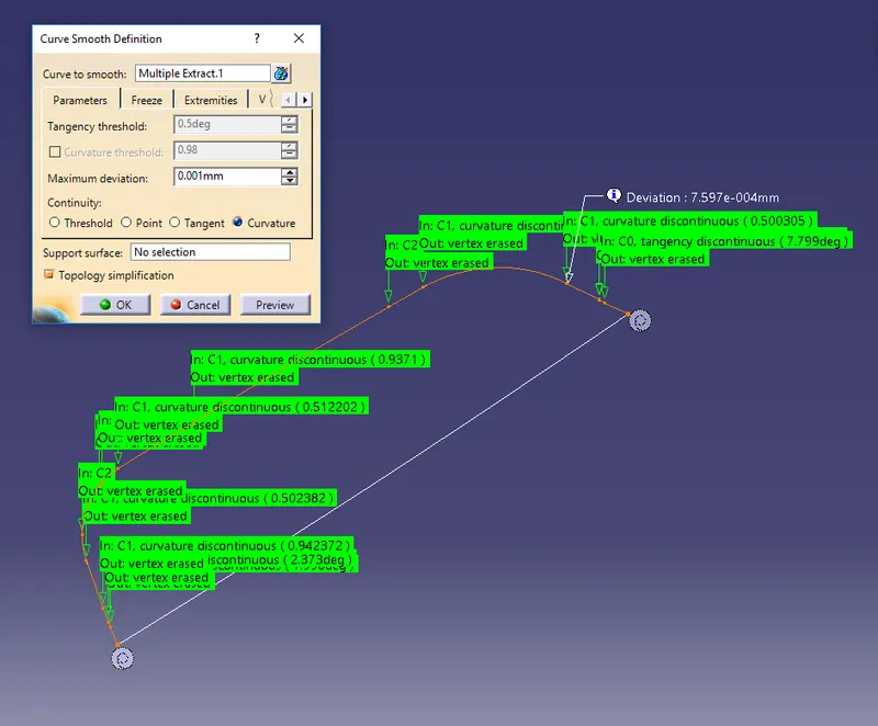
After extracting the boundary, we need to perform smooth (max. Deviation as 0.001mm) operation on it in order to create a continuous tangent surface.
Now using the ‘sweep’ option create the surface. To perform this operation, Go to the Toolbar > Sweep > Profile type > Line > Subtype > With draft direction > Guide curve 1 - (select the extracted boundaries) > Draft direction - (select the tooling axis) > angle as 3 deg and give any suitable length and press ok.
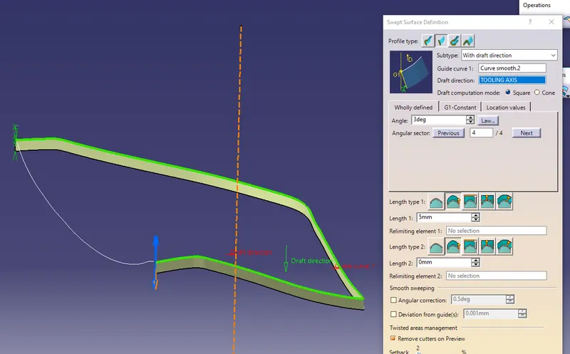
Note: The boundaries of the CLASS A surface needs to be extracted separately (because of sharp edges) and the sweep operation also needs to be done separately.
Once these sweep surfaces are created, trim it to join the surfaces. This will give us a CLASS C surface.
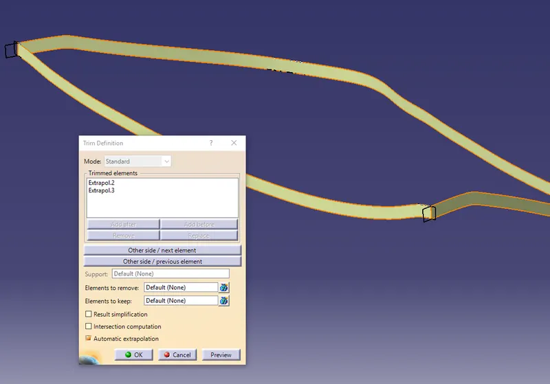
FINAL TRIM :
To create the Door Applique component we need to join all these surfaces (i.e, CLASS A,B and C surfaces).
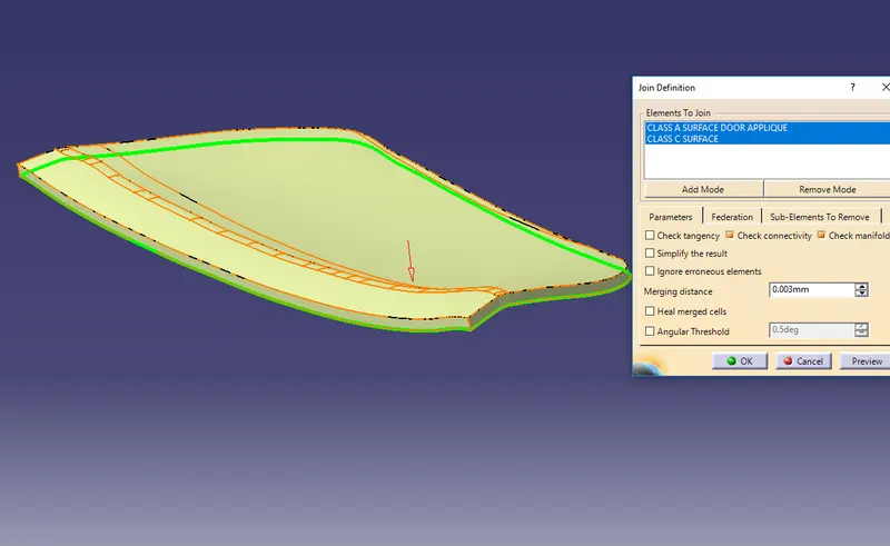
First join the CLASS A surface with the CLASS C surface and then trim this joined surface with the CLASS B surface to get the final output.
CLOSED SURFACE:
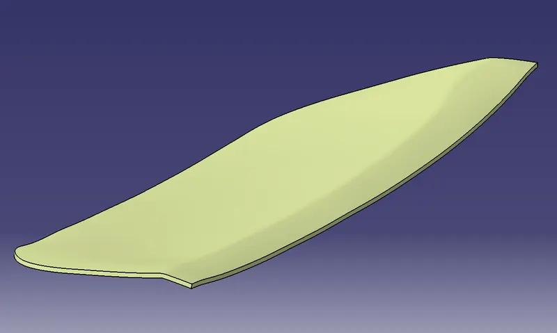
Since these surfaces are hollow, we need to close it to form a thick solid component.
using the “CLOSE SURFACE” option in PART WORKBENCH, a solid body from the surface can be formed.
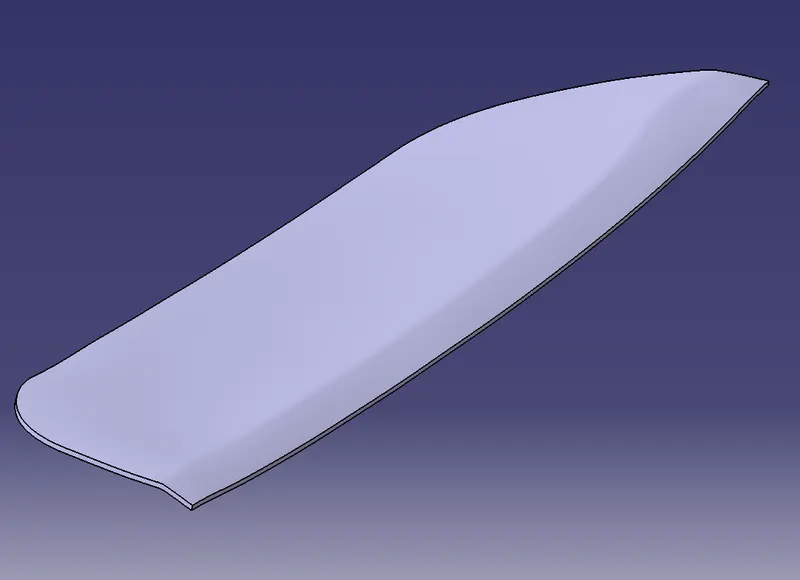
This will give us a solid component. (Door Applique without engineering features).
ENGINEERING FEATURES:
4 - way and 2 - way locator:
Locators are a great way to make sure the parts we are putting together fit the way we want them to fit. The difference between a 4 way and a 2 way locator is that the 4 way locator prevents movement at 2 axis on the plane whereas a 2 way locator only prevents movement at 1 axis on the plane.
To create a 4 way locator, we need to create a sketch with two lines intersecting each other perpendicularly forming a ‘+’. Once the sketch is created, pad it to form a locator.
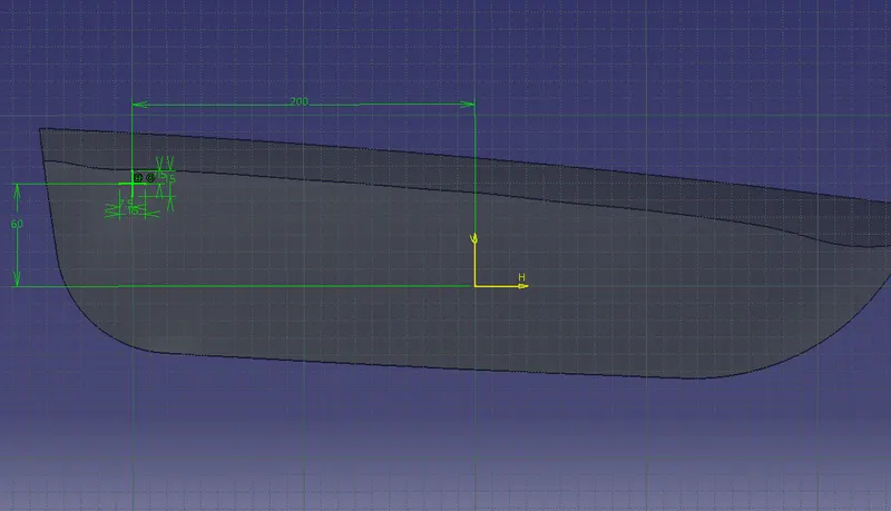
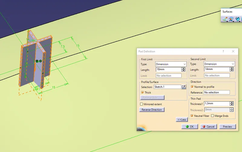
Using the translate option, we can copy-paste this locator by moving it to a required distance.
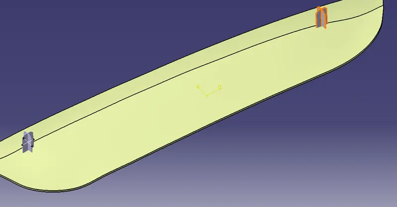
By creating a new sketch with a single line, similar operations can be performed to form a 2 way locator.
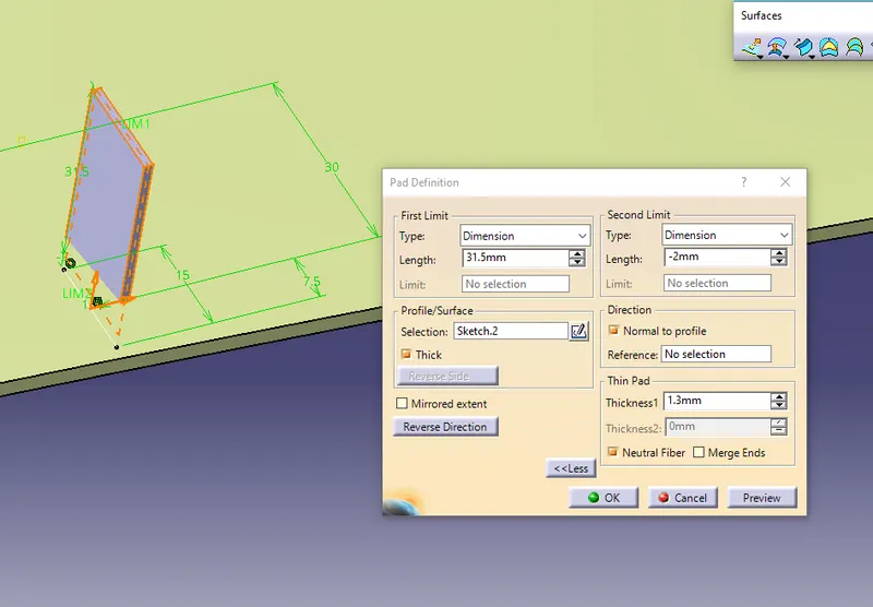
A draft of 0.5 deg is given for both the locators and also a chamfer of 5mm at 45 angle is given to the top edges of the locators.
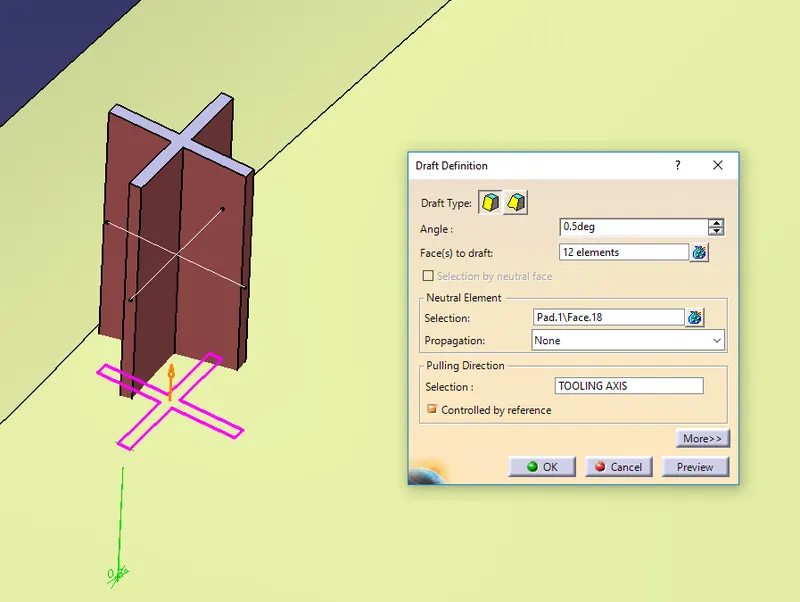
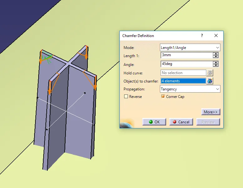
Once the locators are created with the design rules, add it to the Door Applique.
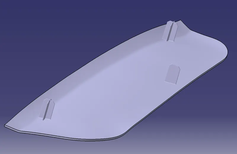
Heat Stakes:
Heat stakes are used to join two or more parts that are made of plastic with the help of heat staking process. Heat staking process involves deformation of the plastic material using heat and force to fix it with the other parts.
To create the Heat Stakes, we need to create a sketch with 2 circles of diameter 5mm and 7mm respectively. Now pad this sketch to form a solid and give it a draft of 0.5 deg.
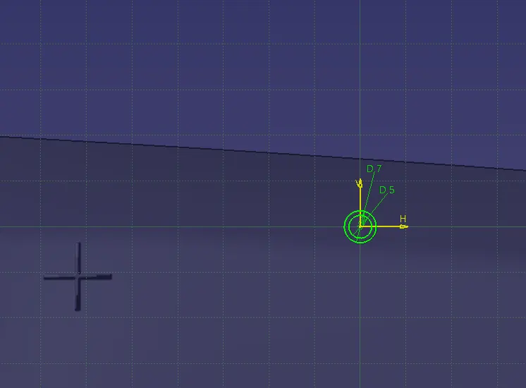
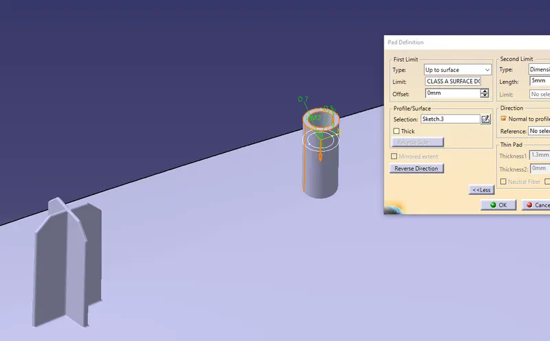
In order to fit the Door Applique to Door Attachment we need more number of Heat stakes. This can be done easily by using the translate option.
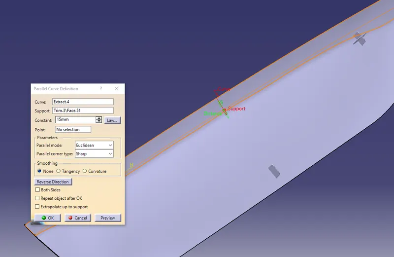
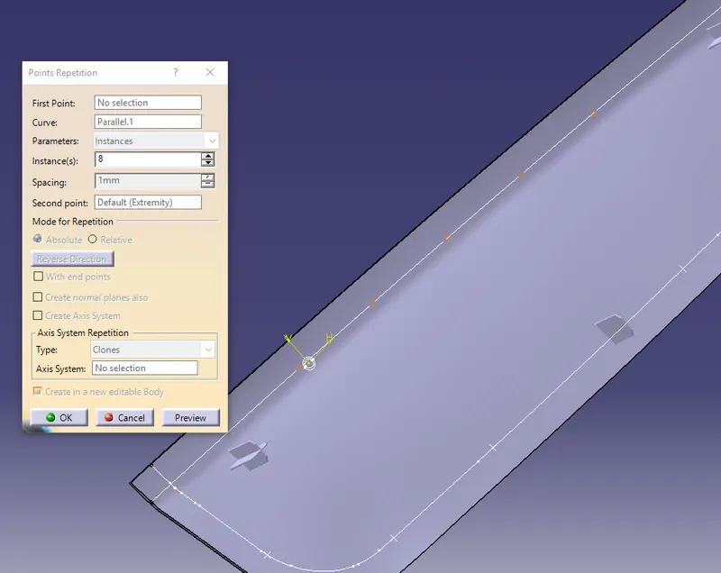
To translate the Heat stakes we need points which are 50mm apart from each other. In order to create these points we first need to extract the boundary of the Door Applique. Now using this boundary a parallel curve is created at a distance of 15mm.
Now using the “repetition of points” option we can create multiple points on the curve at a distance of 50mm from each other.
Using the translate option these Heat stakes can be moved from one point to the other.
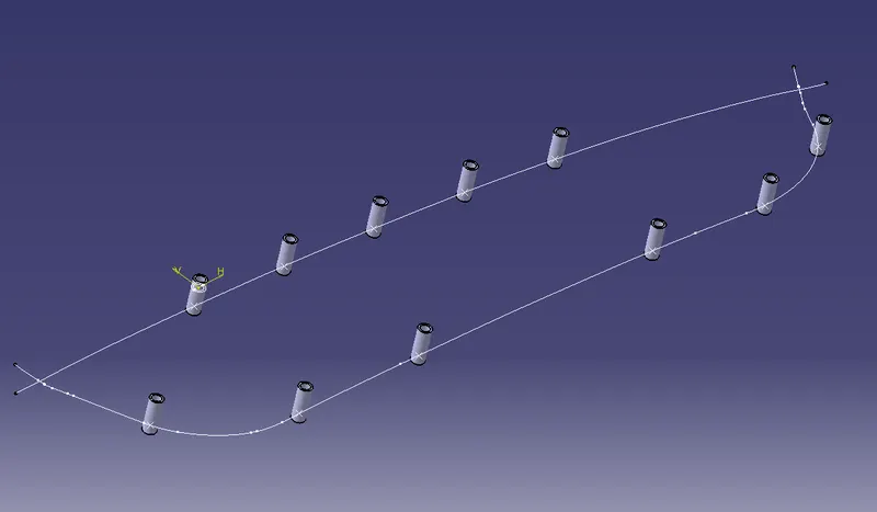
Once all the Heat stakes are created add it to the Door Applique.
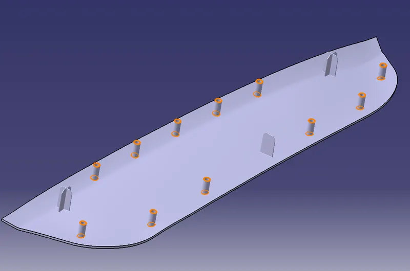
Creating Holes on the Door Attachment:
In order to fit the Door Applique on to the Door Attachment, we need holes on the Door Attachment opposite to the Locators and Heat Stakes.
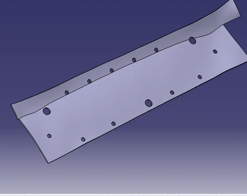
The holes on the attachment must be created considering a clearance of 0.1mm for the locators and 0.5mm for the heat stake.
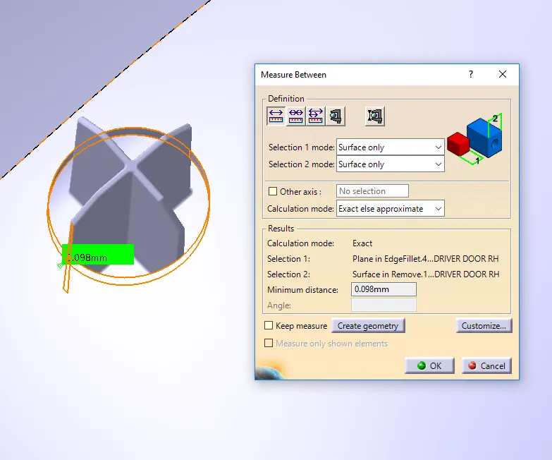
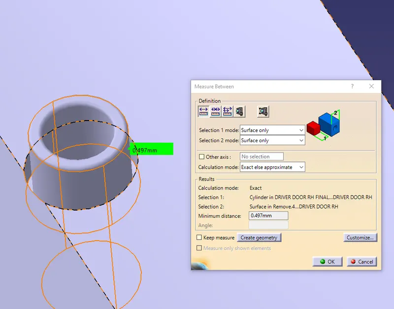
DRAFT ANALYSIS ON FINAL MODEL:
To perform Draft Analysis on the 3D CAD model, Go to menu bar > select insert > Analysis > Feature Draft Analysis.
To give draft direction, use the compass and align it with the tooling axis which we created for the model. Once it is properly aligned, select the surface of the model which will show us the draft angle given on the component. Make sure the draft angle on the component is having 3 deg draft value (component showing green in colour). If the draft value is negative (component colour in red) then we need to adjust the tooling axis direction with the help of compass.
DRAFT ANALYSIS from A SIDE:
DRAFT ANALYSIS from B SIDE:
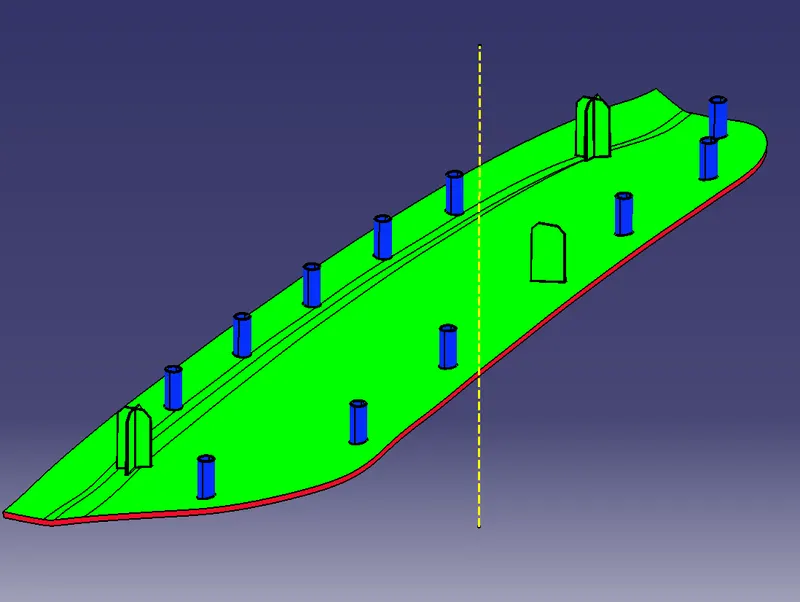
Note: Draft value ranging from 0 - 3 deg will show the component Blue in colour.
Using the Analysis option under Display Tab, we can check / analyze the exact draft value at any point on the given model.
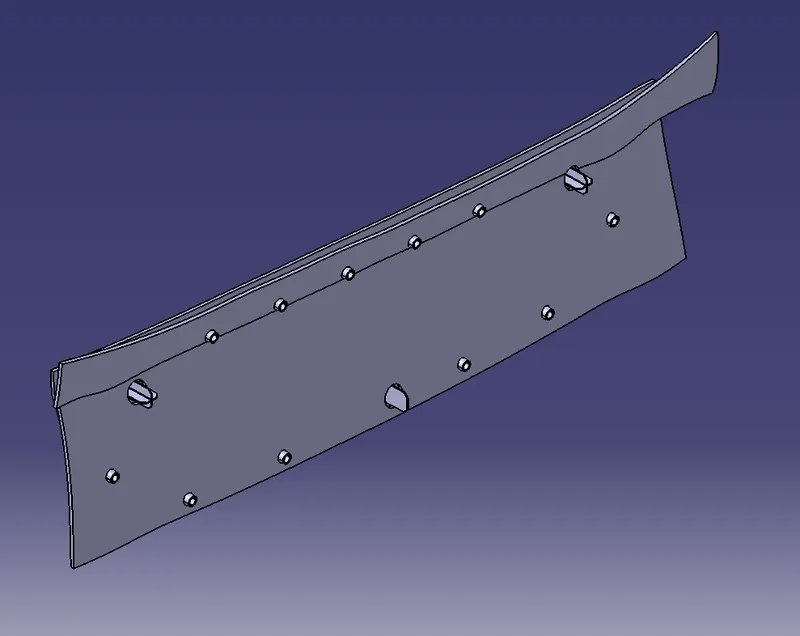
3D CAD MODEL:
TREE STRUCTURE:
Result:
Door Applique plastic component with engineering features using CLASS A surface have been successfully created and draft analysis have also been performed for the same.