Development of a Door Trim Panel
Aim:
To create a CAD model (Door Trim Panel) with attachment features considering the given inputs, design rules and following the OEM standards.
Abstract:
The project report deals with the explanation of steps and procedure followed while developing the Door Trim Panel of a car using CATIA V5. Using the CLASS-A surface and master sections as input, we were able to create a Tooling axis, CLASS-B surface, CLASS-C surface, Flanges and form a solid body after which the attachment features such as Dog House, Push Pins, Heat stakes, etc are created. To check the manufacturability of the parts, a Draft Analysis has also been performed using the main/side tooling axis on various components such as lower substrate, map pockets, armrest, etc.
Methodology:
- CLASS-A surface extraction
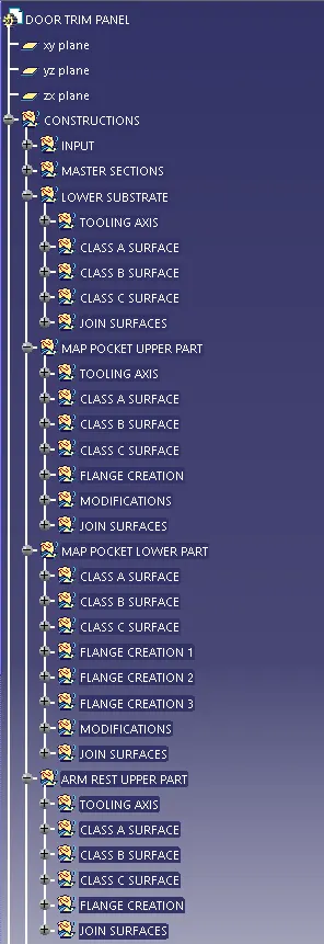
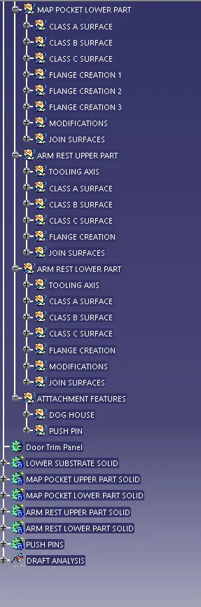
- Creation of different Geometrical sets for each component such as lower substrate, map pocket (upper & lower part), armrest (upper & lower part), etc.
- Tooling Axis / Side Core Axis Creation
- Creation of Flanges
- Creation of CLASS-B Surface
- Creation of CLASS-C Surface
- Joining of CLASS-A, B & C Surface
- Performing a check for boundaries
- Forming a Solid Body
- Attachment features creation
- Performing Draft Analysis
Procedure:
The first step to follow in this project is to extract the CLASS-A surface (individually for each component) of the Door Trim Panel and divide these surfaces into different Geometrical sets as follows.
- Lower Substrate
- Map Pocket Upper Part
- Map Pocker Lower Part
- Arm Rest Upper Part
- Arm Rest Lower Part
1. Lower Substrate:
CLASS-A surface extraction:
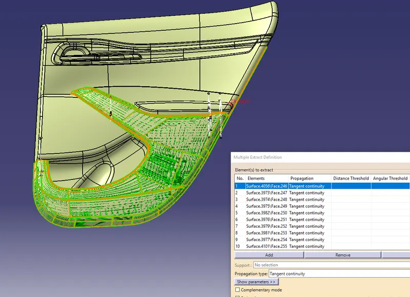
Initially, we need to extract the CLASS-A surface for the Lower Substrate from the given input.
Tooling Axis:
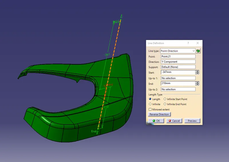
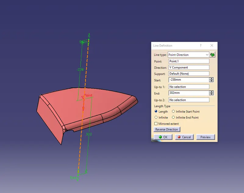
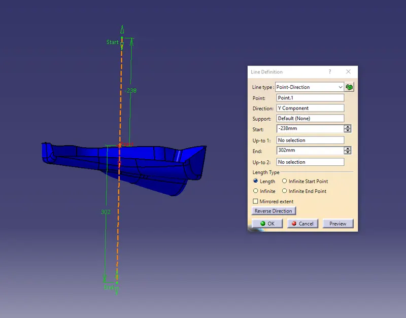
A tooling axis needs to be created in a direction from which it can capture most parts/features of the component. Generally, a tooling axis will be created perpendicular to the base surface of the component.
In this case, we need to create the tooling axis in the Y-direction. So to create the tooling axis in Y-direction, we first need to create a point and using this point create a line giving direction in the Z-axis. This line will give us the Tooling Axis.
Draft Analysis on CLASS-A surface:
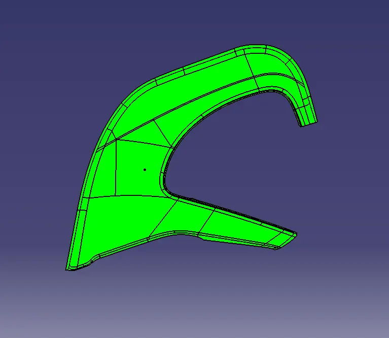
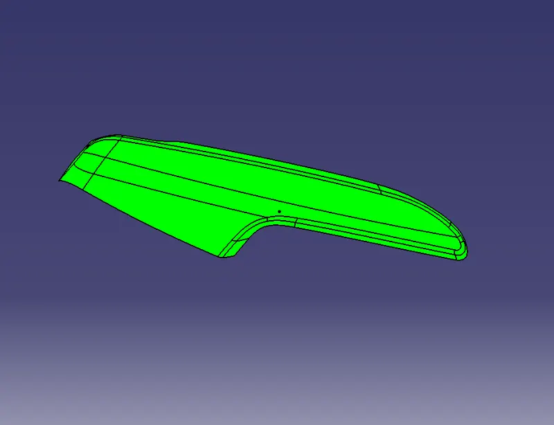
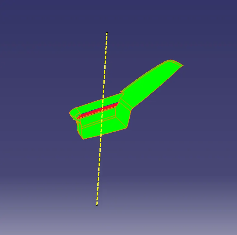
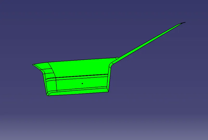
To ensure if the Tooling Axis we created is proper, we need to inspect the CLASS-A surface by performing a Draft Analysis on it.
CLASS-B surface:
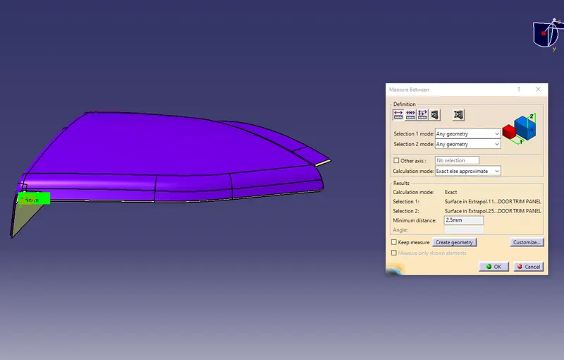
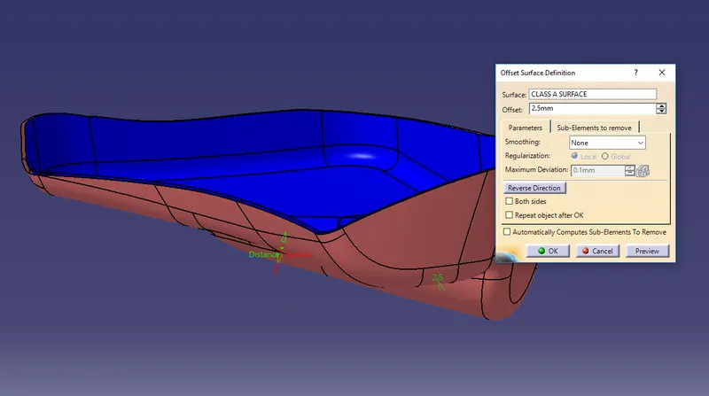
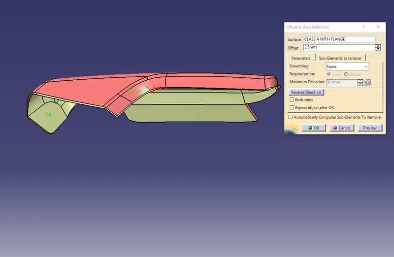
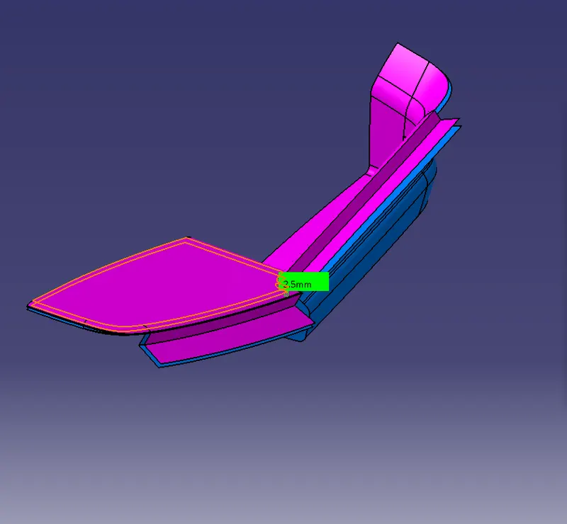
To create the CLASS-B surface, the CLASS-A surface is offset by 2.5mm (since the thickness of the component is 2.5mm). From the master sections which is given to us as input, we can measure the thickness of the component.
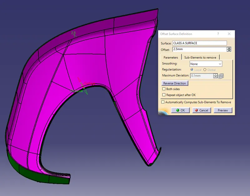
At times few surfaces of the CLASS-B surfaces cannot be offset due to the change in the fillet region. These issues can be fixed by creating the surface manually in those portions. Since there are no issues on this surface we can proceed to the next step.
CLASS-C surface:
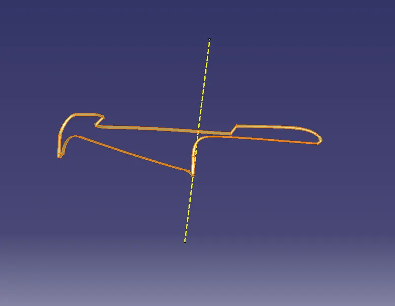
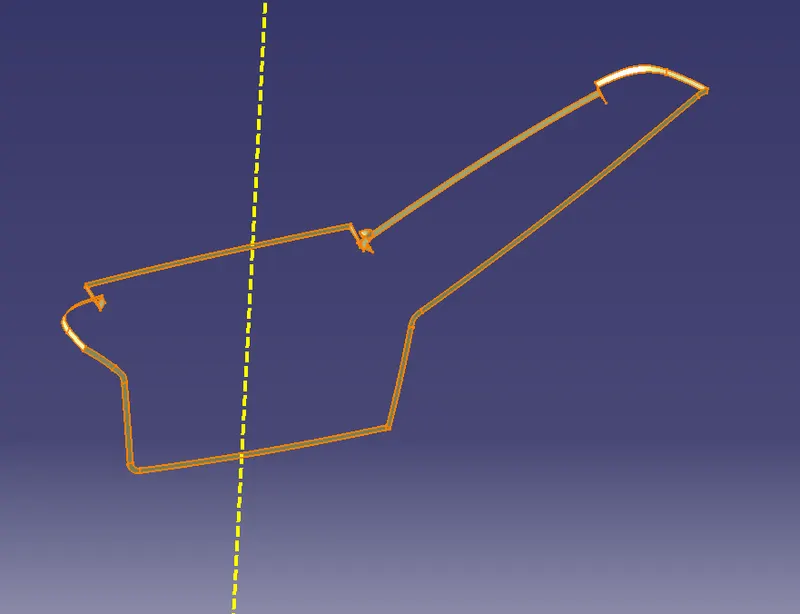
To create a CLASS C surface first extract the boundaries of the CLASS A surface.
After extracting the boundary, we need to perform a smooth (max. Deviation as 0.001mm) operation on it to create a continuous tangent surface.
Now using the ‘sweep’ option create the C surface by sweeping the boundary of the CLASS-A surface at an angle of 3deg outwards to the tooling direction
Note: The boundaries of the CLASS A surface needs to be extracted separately and the sweep operation also needs to be performed separately. It is not possible to create a C surface by a single boundary/sweep following the Draft Direction.
Join all these sweep surfaces to form the final C surface.
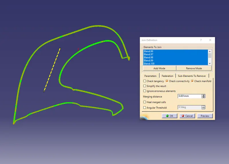
Joining Surfaces:
To form a closed surface we first need to join the CLASS A surface with the CLASS C surface and then trim this joined surface with the CLASS B surface to get the final output.
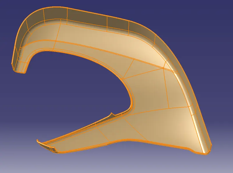
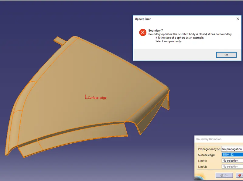
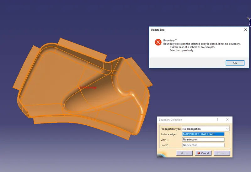
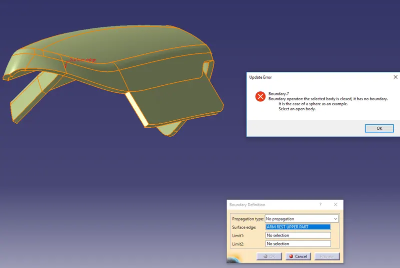
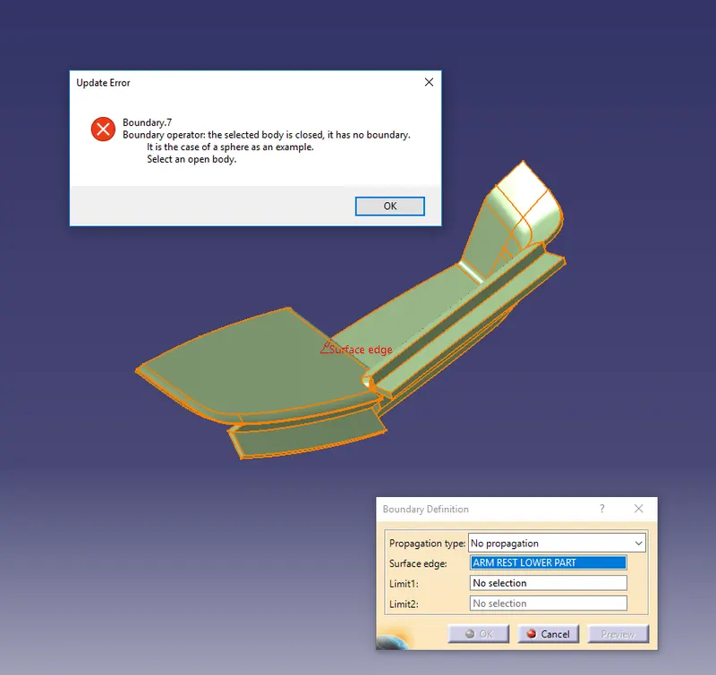
Check if there are any gaps after joining the surfaces by using the boundary option. If there will be any gaps after the joining of surfaces then these gaps need to be fixed to form a closed body.
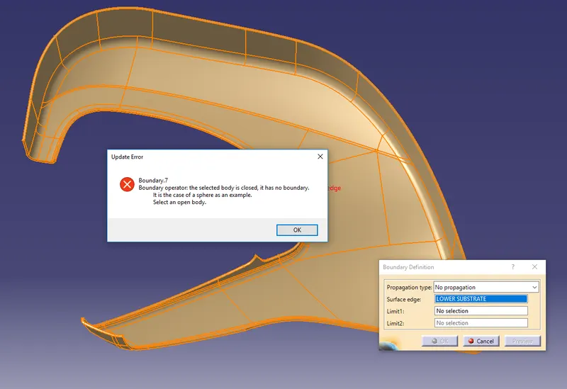
Note: Since there are no gaps found, the body is said to be a closed body.
Forming a Solid Body:
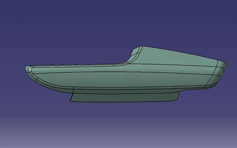
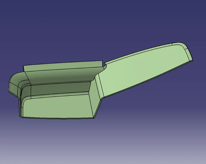
Since these surfaces are hollow, we need to close them to form a thick solid component.
Using the “CLOSE SURFACE” option in PART WORKBENCH, a solid body from the closed surface can be formed.
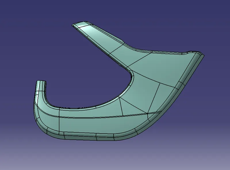
2. Map Pocket Upper and Lower Part:
CLASS-A surface extraction:
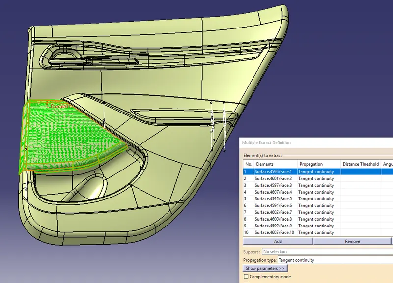
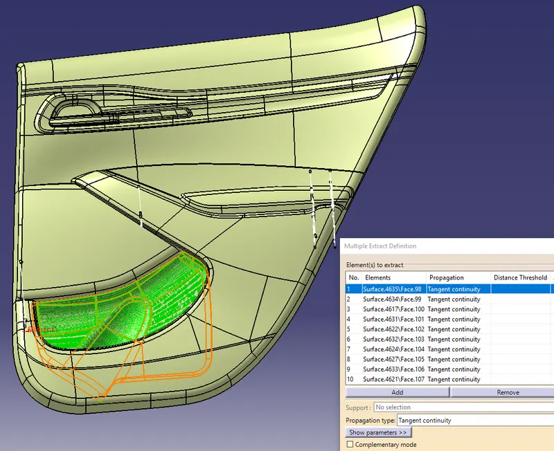
Now again from the input which was given to us, we need to extract the CLASS-A surface for the Map Pocket Upper and Lower Part separately in a different geometrical set.
Tooling Axis:
The creation of the tooling axis for this component is the same as mentioned for the above part.
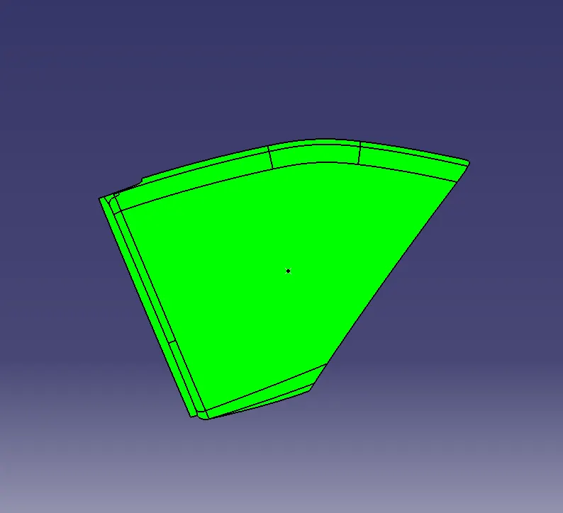
Draft Analysis on CLASS-A surface:
Creating Flanges:
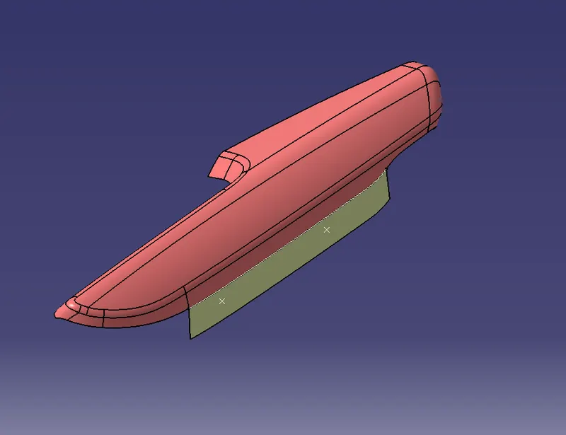
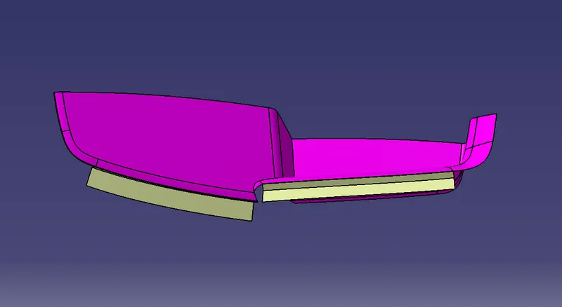
Flanges are needed to join the components. Following the master sections, we can create these flanges and attach them to the CLASS-A surface.
To create a Flange, we first need to extract the boundary (only where the Flange is required) of the CLASS-A surface. Sweep this boundary with the reference surface (CLASS-A) making an angle of 90 deg.
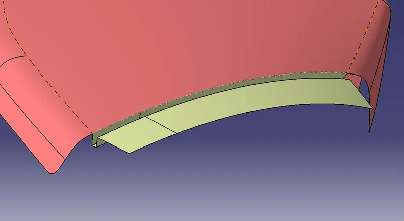
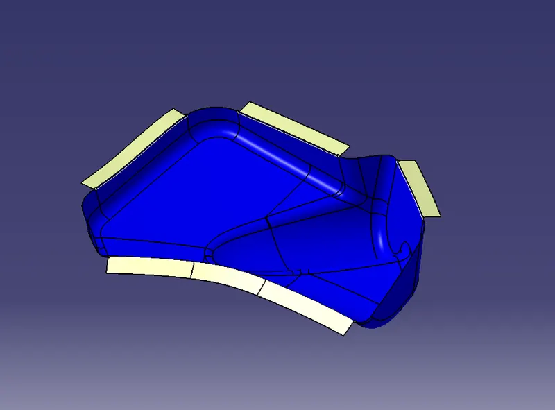
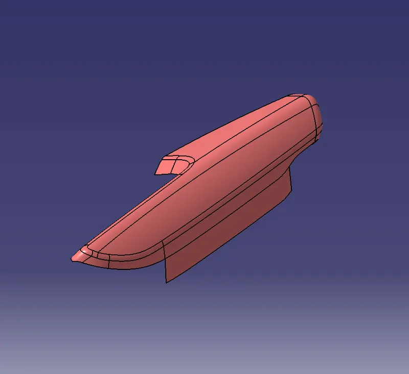
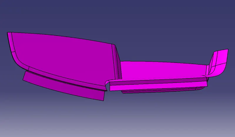
A Flange is created and it can be joined with the CLASS-A surface.
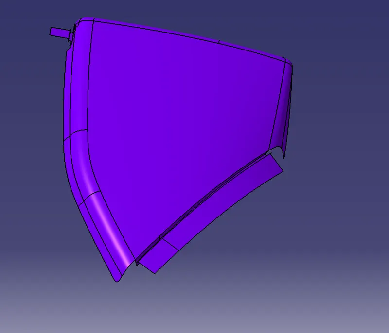
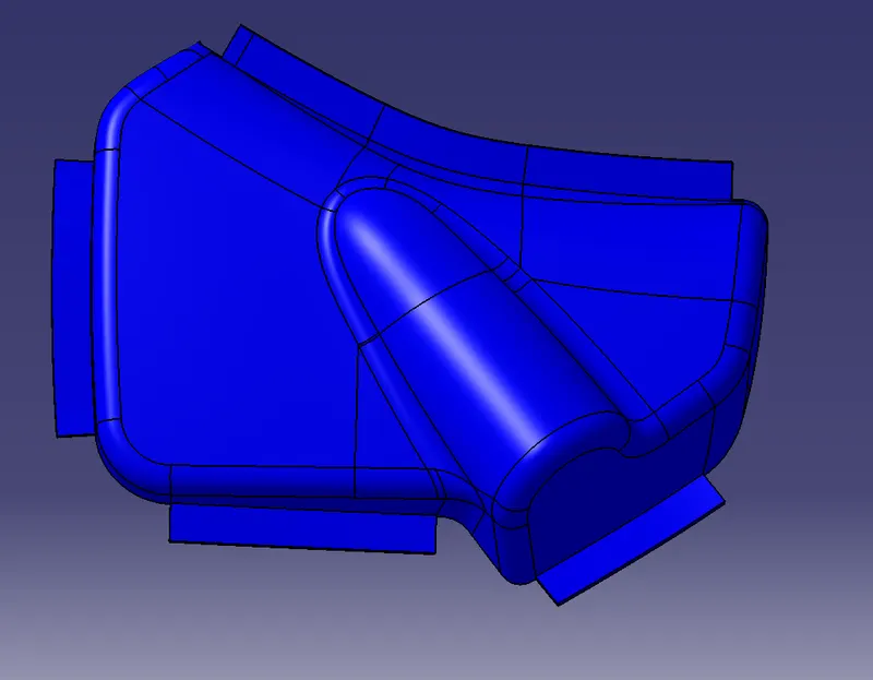
Note: The holes in the flanges can be created later after creating the heat stakes to get proper clearance.
CLASS-B surface:
The steps and procedure for creating the CLASS-B surface is the same as mentioned for the above part.
CLASS-C surface:
Also for the CLASS-C surface, the steps and procedure is the same as mentioned for the above part.
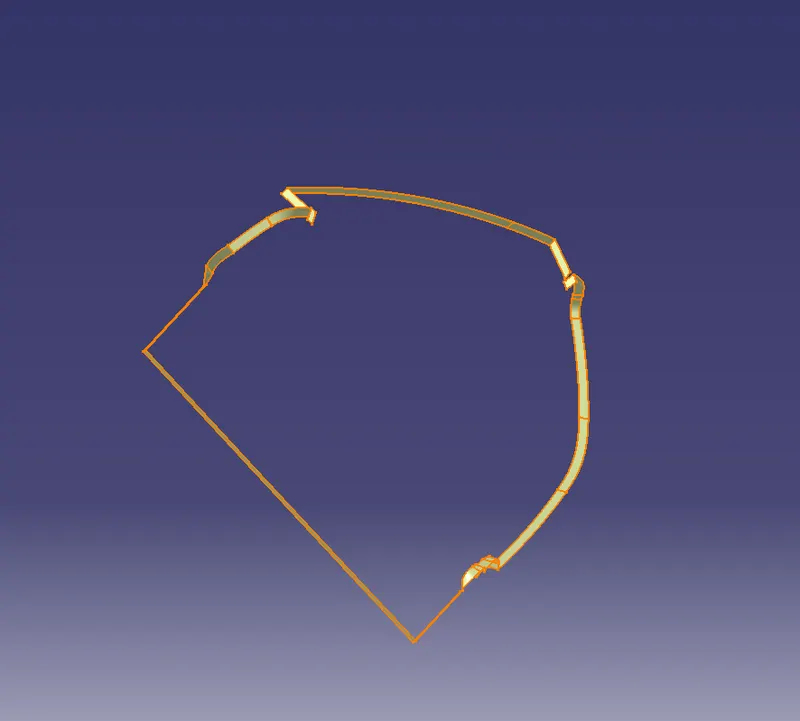
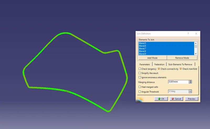
Note: Since few parts of the components can be cleared at 90 deg to the tooling axis, there is no need to use the sweep operation every time. The C surface can also be created there using the 'Blend' option.
Joining Surfaces:
To form a closed surface, join the CLASS-A surface with the CLASS-C surface and then join/trim this surface with the CLASS-B surface to form the close body.
Forming a Solid Body:
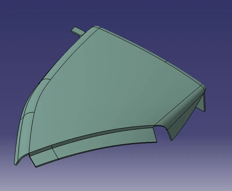
Using the “CLOSE SURFACE” option in PART WORKBENCH, a solid body from the closed surface can be formed.
3. Arm Rest Upper Part and Lower Part:
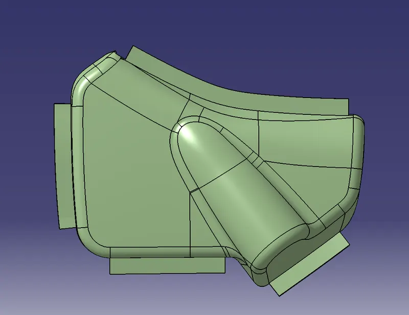
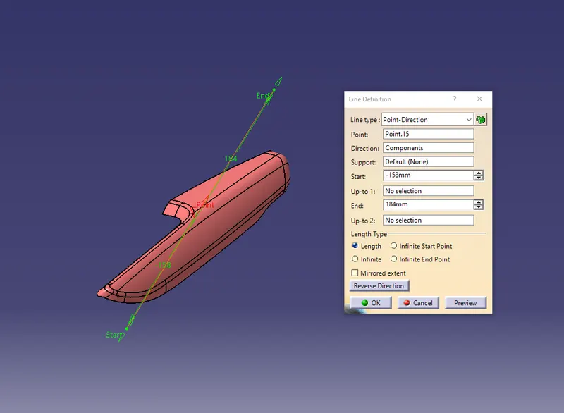
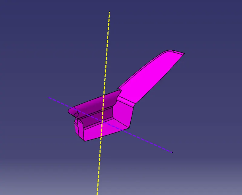
To create the surfaces and forming a close body similar steps need to be performed as mentioned for the above parts. But to create a proper tooling axis for Arm Rest Upper Part, we need to adjust the tooling axis since this component cannot be cleared in 90 deg to any (X, Y & Z) of the directions.
For the Arm Rest Lower Part, a side core axis is also required along with the main tooling axis.
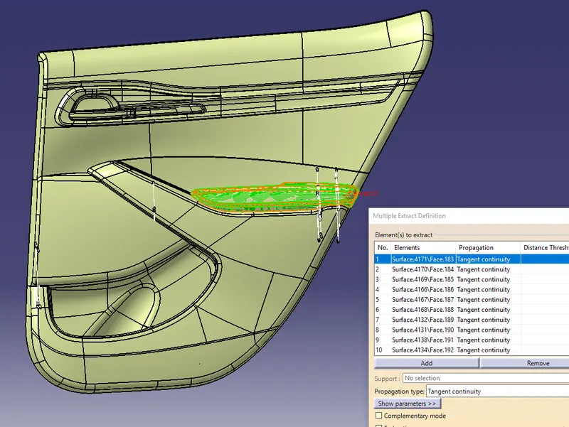
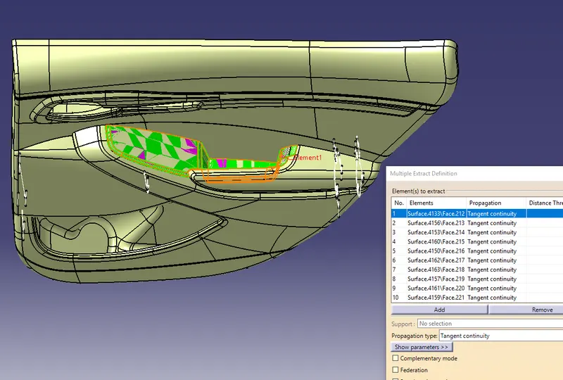
CLASS-A surface extraction:
Tooling Axis:
Draft Analysis on CLASS-A surface:
Creating Flanges:
Joining Flanges with CLASS-A surface:
CLASS-B surface:
CLASS-C surface:
Joining Surfaces:
Forming a Solid Body:
Attachment features creation:
Heat Stakes:
Heat stakes are used to join two or more parts that are made of plastic with the help of the heat staking process. The heat staking process involves the deformation of the plastic material using heat and force to fix it with the other parts.
To create the Heat Stake, we need to create a sketch with a circle of diameter 8mm. Now extrude this sketch to a height such that it is passing through the Flange. Using the shell option, thicken this extrude (thickness 2mm) to form a solid and give it a draft of 0.5 deg.
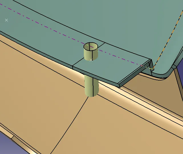
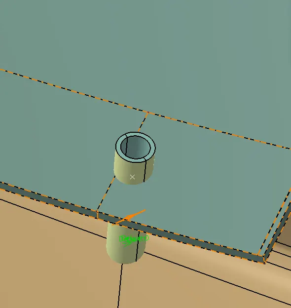
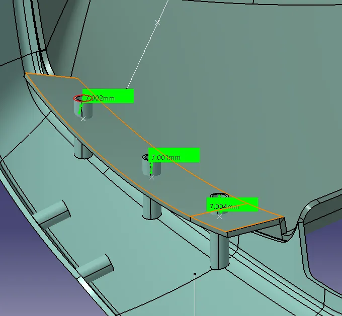
Make sure a 7mm distance must be maintained between the Flange top surface to the top surface of the heat stake.
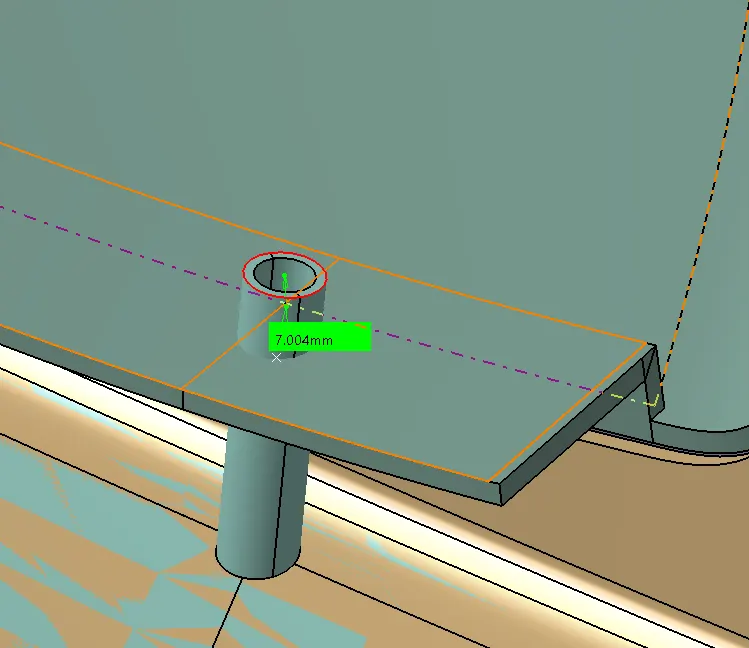
To fit all the components with each other, we need more number of heat Stakes at various locations such as on the Lower substrate, Map Pocket Upper Part and Arm Rest Upper Part. This can be done easily by using the translate option.
Note: 60-65mm gap needs to be maintained between the heat stakes.
Points are needed to position these heat stakes. Once all the points are created, the solid body of the heat stake can be copied and paste on the tree structure multiple times (depending on the requirement, heat stakes need to be copy-paste).
Now using the translate option move these heat stakes from one point to another.
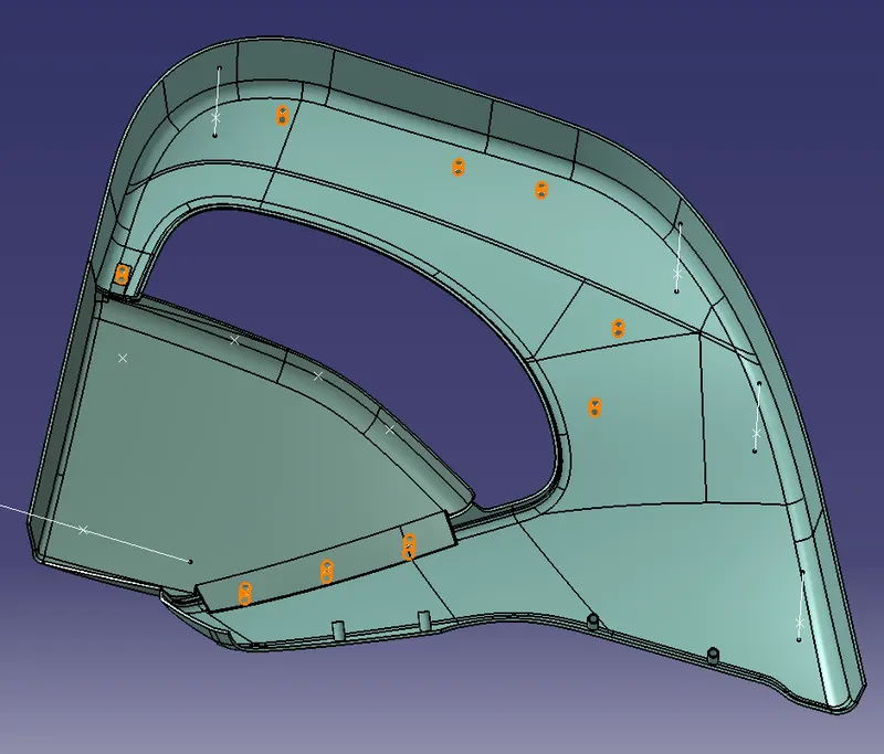
Once all heat stakes are translated, make sure to check the height of them. All the heat stakes must be maintaining a 7mm distance from the Flange top surface to the top surface of the heat stake. If any of the heat stakes is not maintaining the required height then adjust the height by translating it in Y-direction.
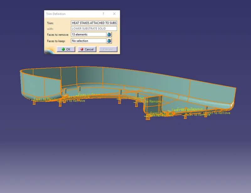
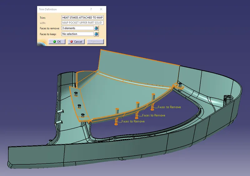
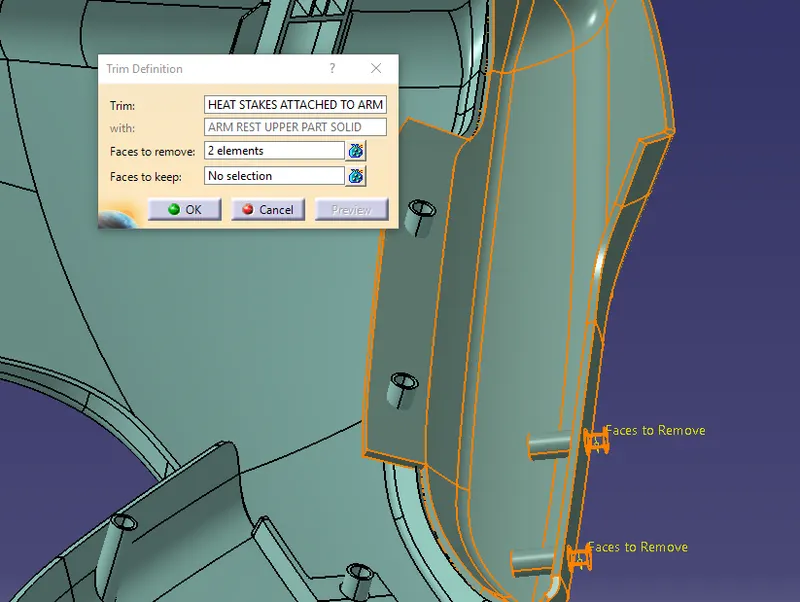
Now using Boolean operations, add these heat stakes to the solid bodies (Lower substrate, Map Pocket Upper Part and Arm Rest Upper Part).
Creating holes on Flanges:
A clearance of 0.5mm must be maintained between the hole and heat stake. So to create a hole, we need to extract the outer surface of the heat stake and offset it to a value of 0.5mm.
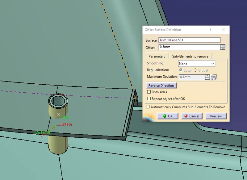
Split the solid body using these offset surface to make a hole in the Flange.
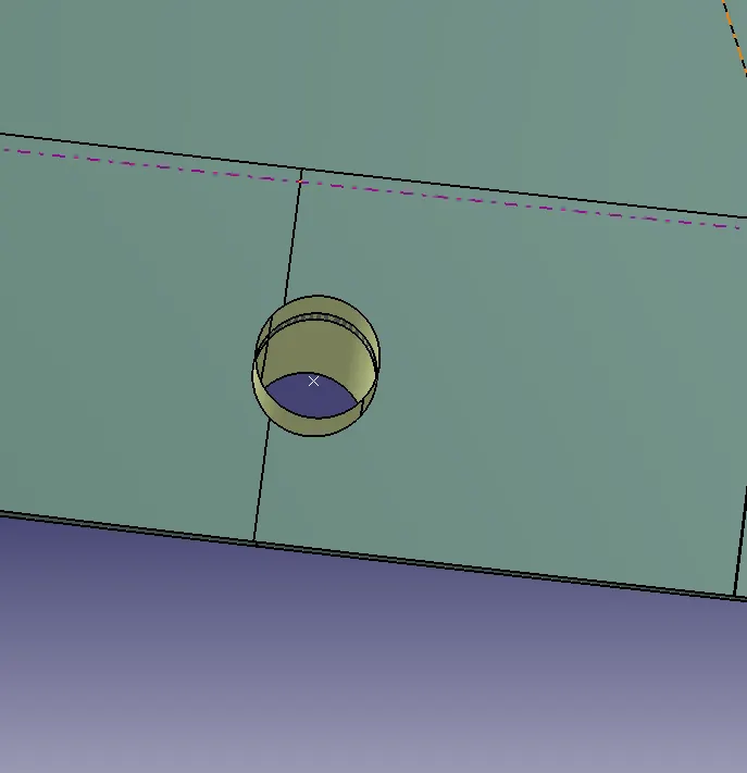
The offset surface can be translated to other positions (using the same points created for heat takes translation) where a hole is required.
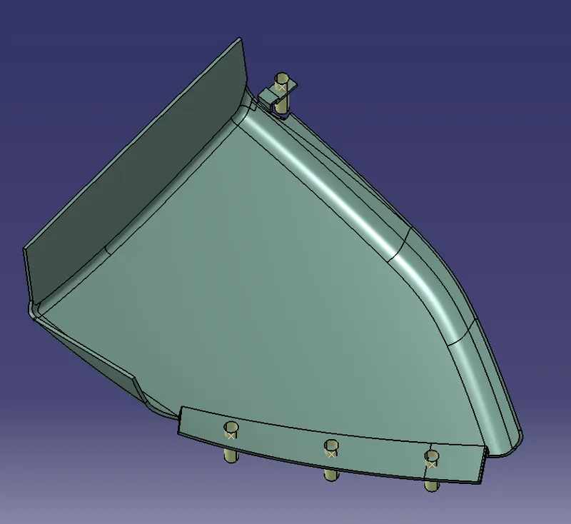
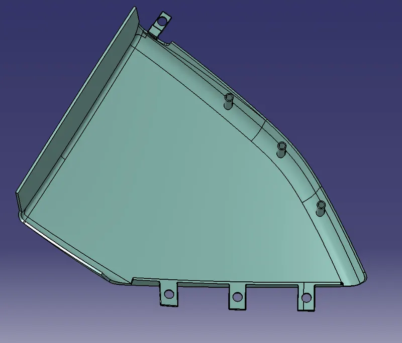
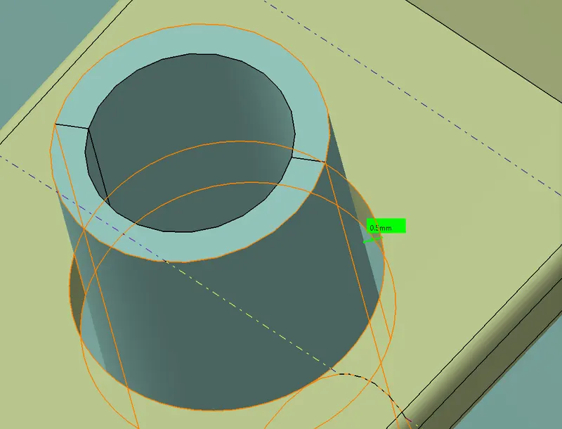
Note: I have removed the excess solid portion of the flange to give it a proper shape. This step is not required and can be avoided if we were given the shape of Flange while surface creation only.
Dog House:
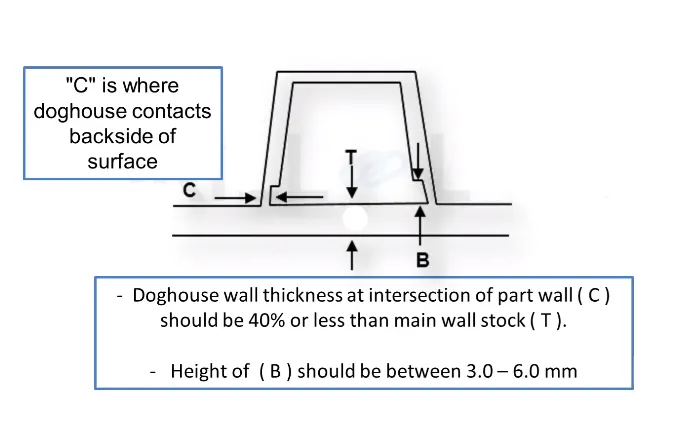
The Dog House is an engineering feature that is used in the plastic trim design. It is used as a supporting feature for other engineering features like snaps, locators, push pins etc. that are mounted on the Dog house to increase their strength and also to avoid the sink marks.
To create the Dog House, we first need to create a sketch that is rectangular with one side is open and then extrude it.
Now using thicken option in PART WORKBENCH, give it a thickness of 2mm to form a solid.
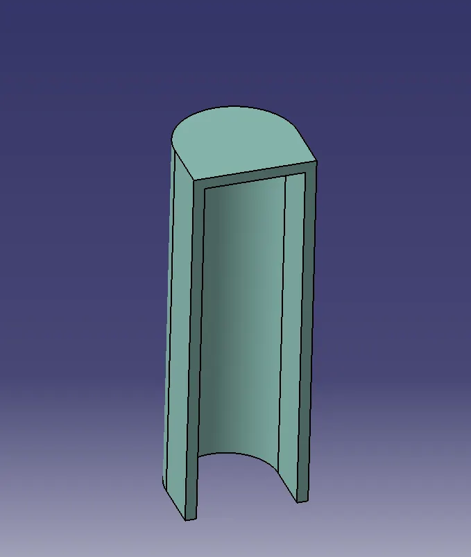
Now using another sketch, give a shape for the top surface of Dog House. PAD this sketch and remove it with the solid body of Dog House.
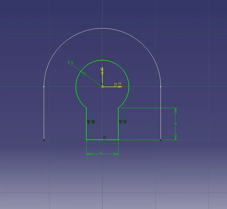
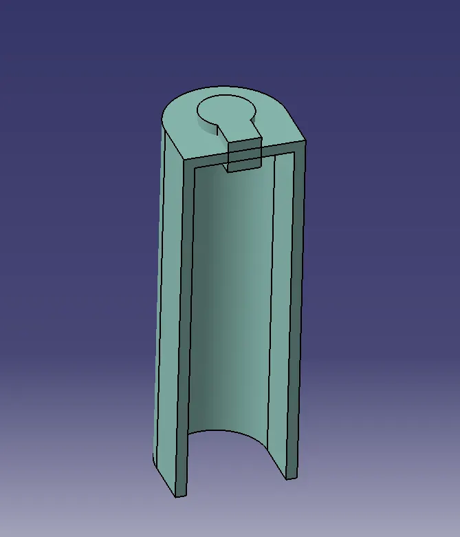
To get the inner shape of the Dog House the following Design Rules are followed.
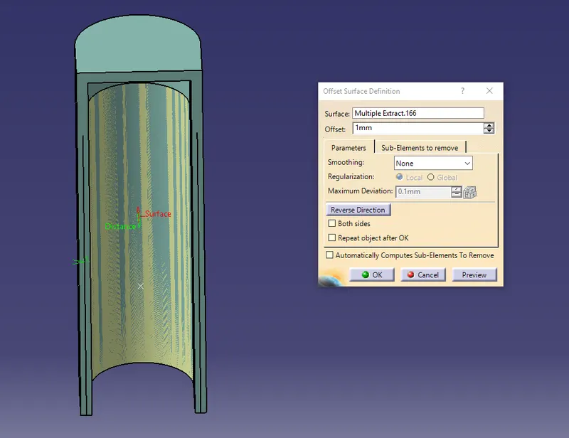
First, we have extracted the inner walls of the Dog House and offset it to 1mm (since the thickness of the bottom portion walls should be 40% of T i.e 2.5*0.4=1mm).
Then the base surface on which the Dog House is going to fixed is extracted and offset by 5.5mm (it can be anywhere between 3-6mm).
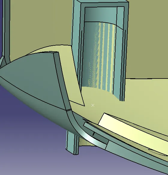
The offset base surface and the offset walls of the Dog House is trimmed together. This trimmed surface is then split with the main/solid body of the Dog House to form the inner shape of the Dog House.
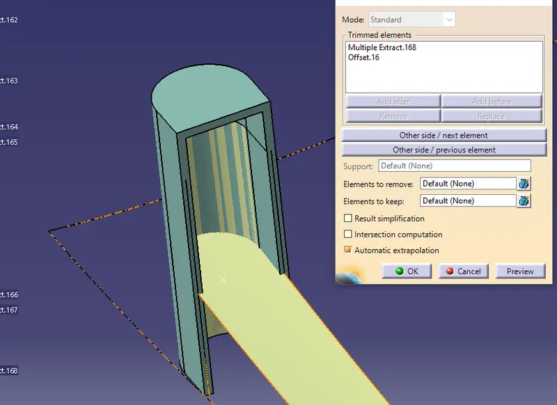
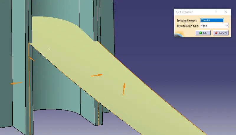
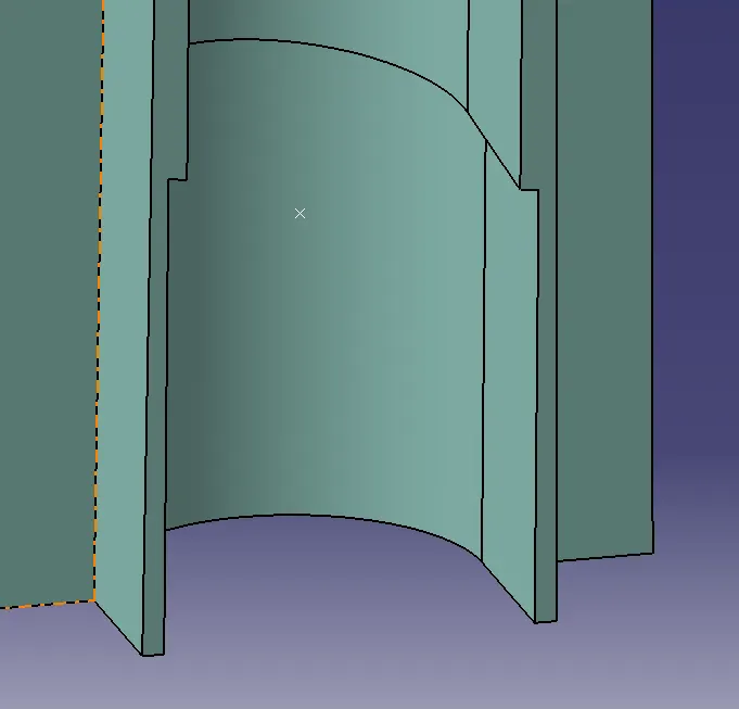
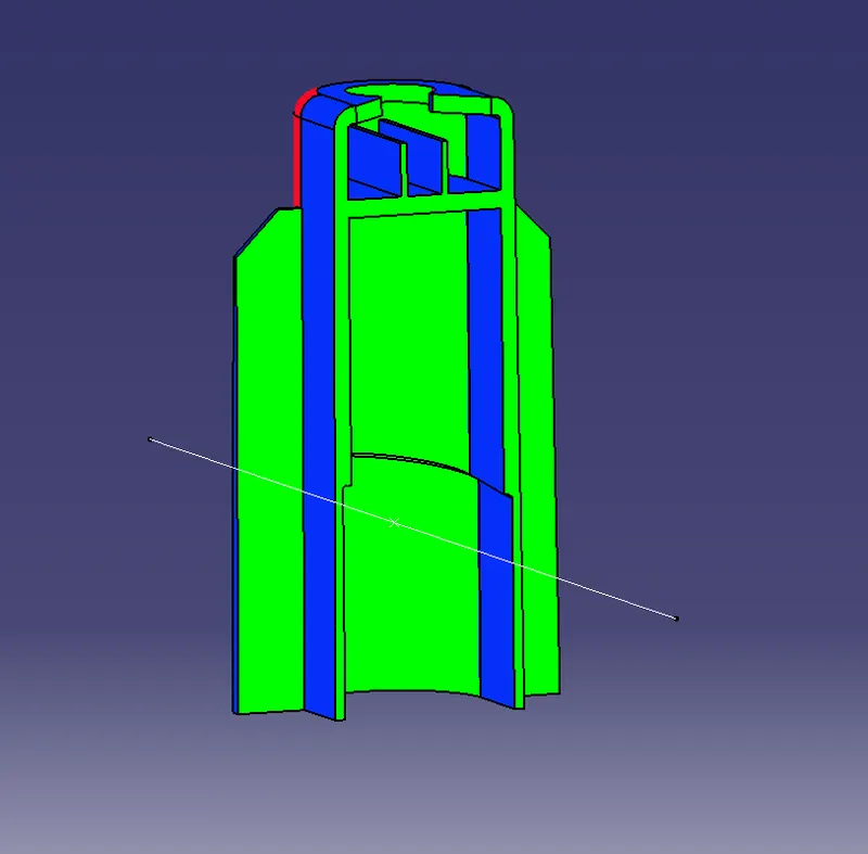
Note: Ribs are created to give strength to the Dog House and a side core axis is also used to draft the inner portion of the Dog House.
The Outer and inner walls of the Dog House is drafted with a 0.5deg draft value.
The Dog House can also be translated from one point to another. But make sure that the base surface for all the Dog House is not similar hence the inner portion should be created separately for all the Dog House.
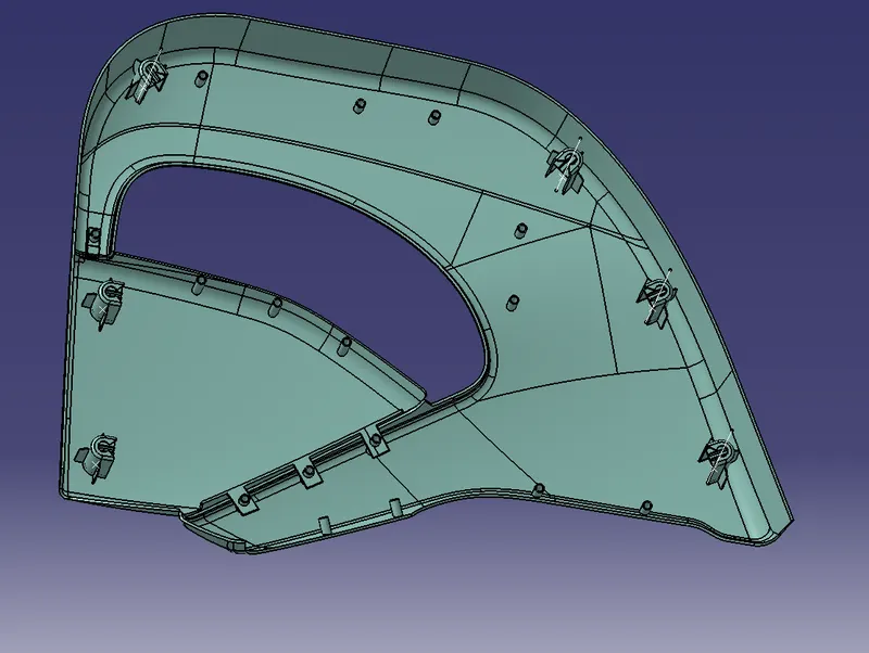
Push Pins:
Push Pins are used for joining one component to another and are attached to the Dog House.
To create a Push Pin a sketch is drawn following the below details.
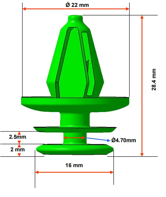
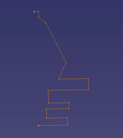
After creating the sketch, a shaft option is used to create a solid circular body.
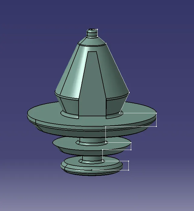
The Push Pin can be translated from one point to another using the same points used for translating the Dog House.
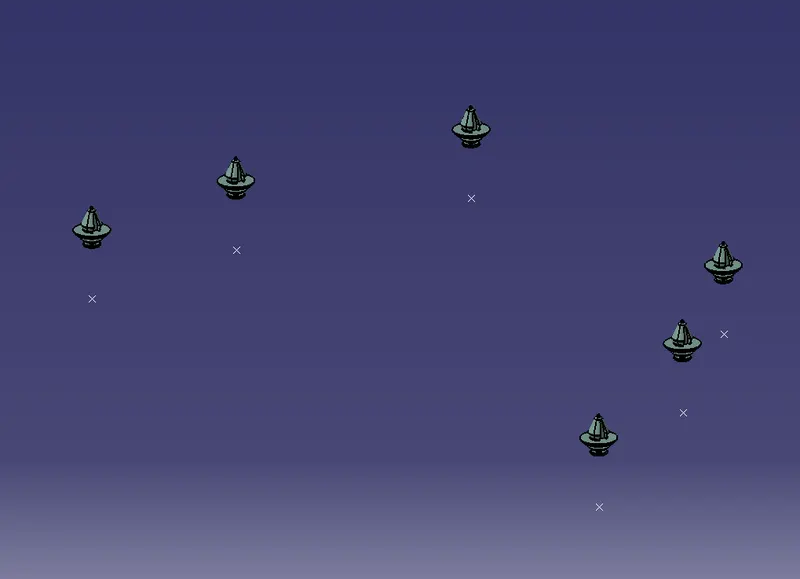
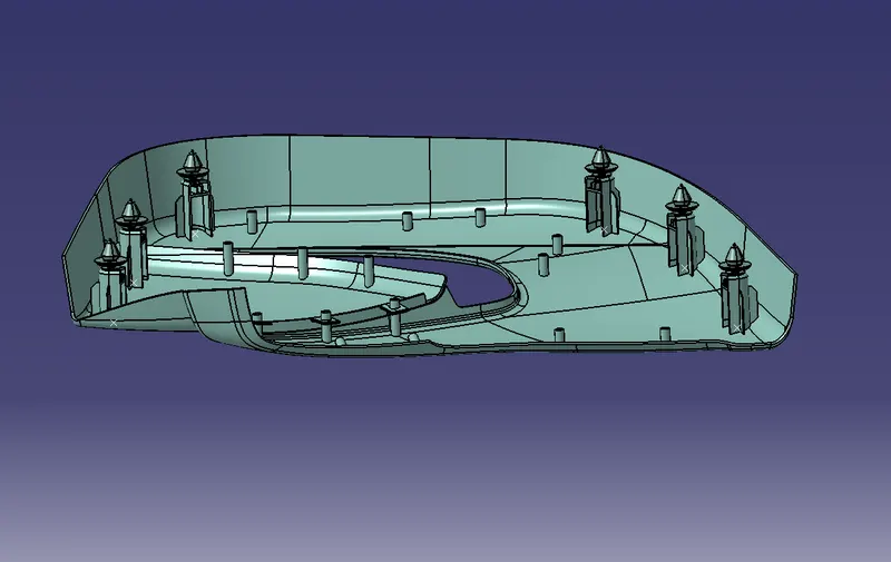
Note: After creating all the solid bodies, chamfer and fillets can be given to them.
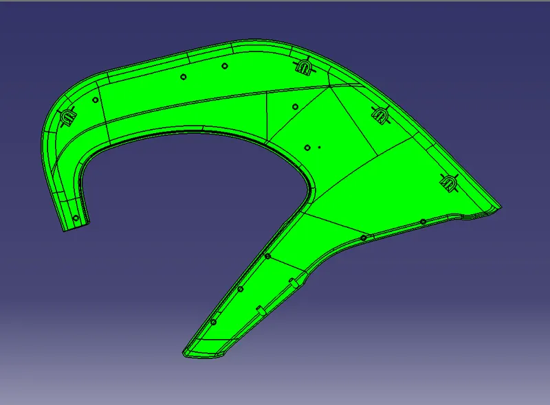
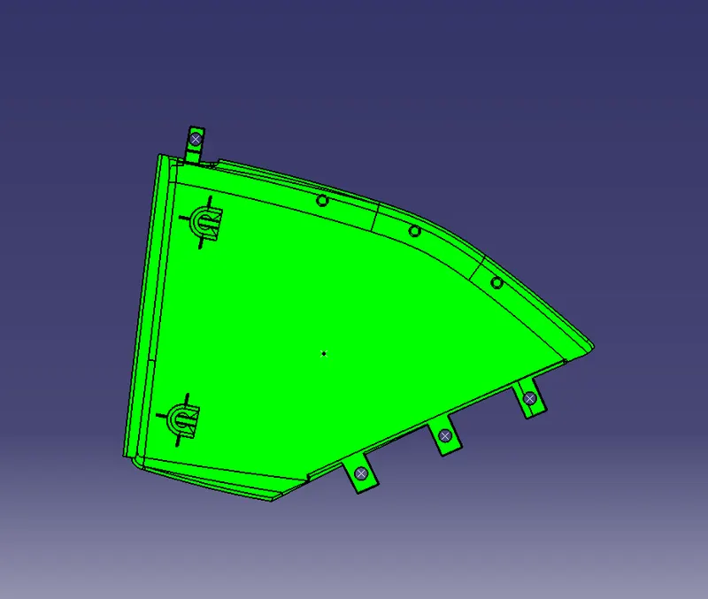
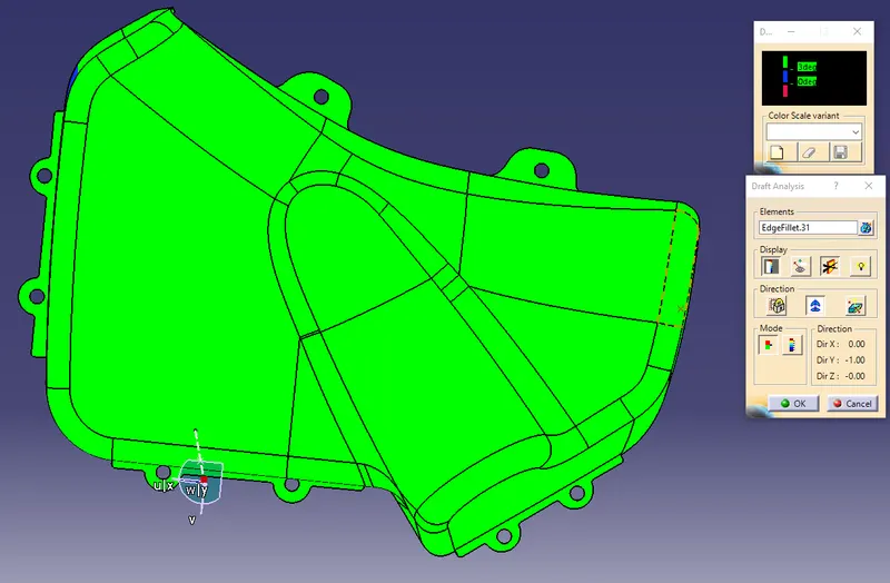
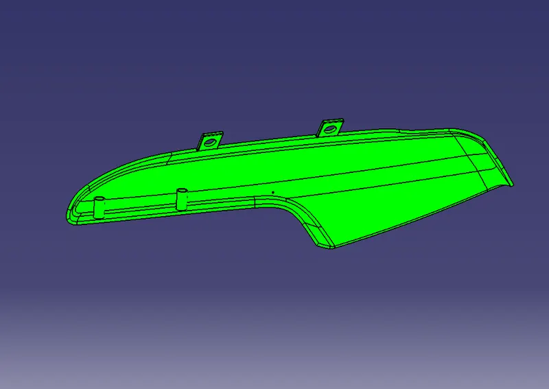
DRAFT ANALYSIS ON CAD MODEL:
Draft Analysis using main tooling axis:
Lower Substrate:
Map Pocket Upper Part:
Map Pocket Lower Part:
Arm Rest Upper Part:
Arm Rest Lower Part:
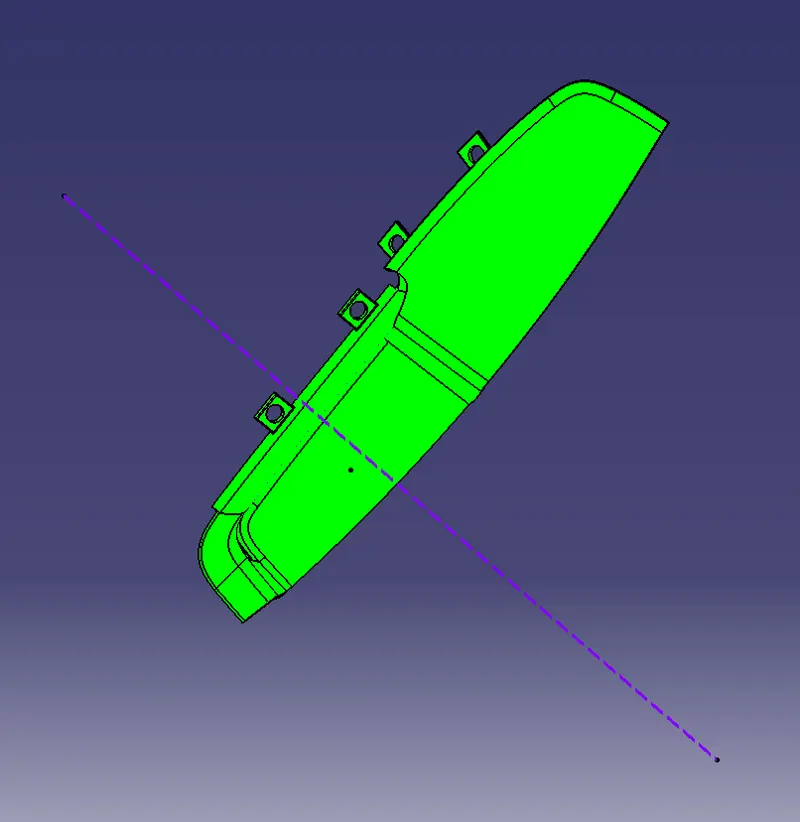
Dog House:
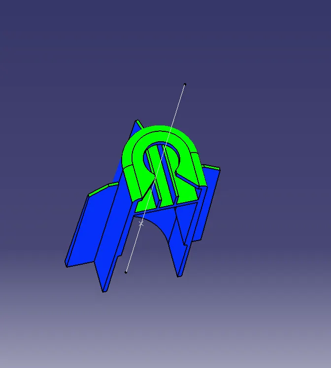
Sliding Axis:
Arm Rest Lower Part:
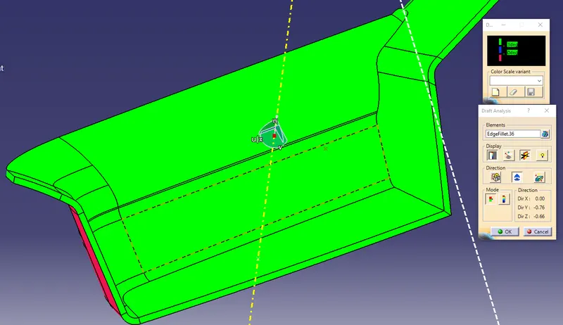
Dog House:
TREE STRUCTURE:
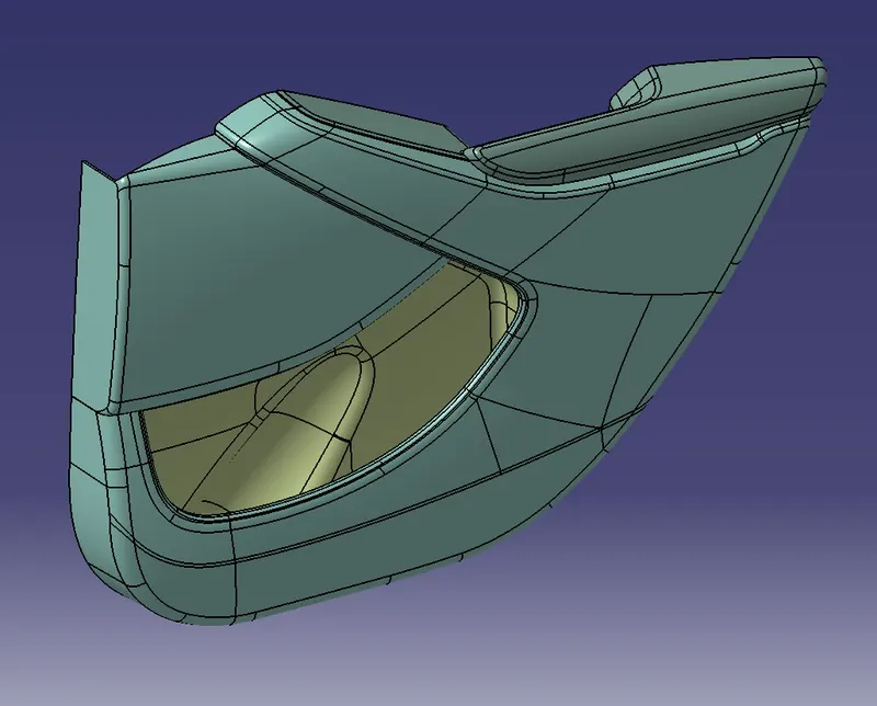
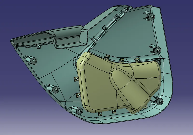
FINAL CAD MODEL:
Result & Conclusion:
A Door Trim Panel with engineering features using the master section and styling surface as an input has been successfully created and draft analysis has also been performed for the same.