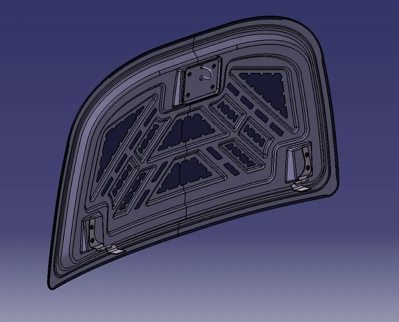
Hood Design
Aim:
To Design & Assemble Hood outer panel, inner panel and the necessary reinforcements by following the Design parameters & Master section which is given to us as an input.
Abstract:
The project report deals with the explanation of steps and procedure followed while developing the HOOD Assembly of a car using CATIA V5. Using the styling surface and master section as input, we were able to create HOOD outer panel and inner panel with features like embossments and mastic points. After creating the HOOD outer & inner panels, we have created a complete HOOD assembly consisting of the outer panel, inner panel, latch, hinge & reinforcements. In the end, a Draft Analysis has also been performed using the main tooling axis to check the manufacturability of the components.
Methodology:
- Creating Hood Inner Panel
- Creating Hood Outer Panel
- Creating Embossment for Hinge
- Creating Embossment for Latch
- Creating Reinforcements
- Assembling the components
- Performing Draft Analysis on CAD Model
Theory:
HOOD:
The hood or bonnet is the hinged cover over the engine of motor vehicles. Hoods can open to allow access to the engine compartment or trunk on rear-engine and some mid-engine vehicles for maintenance and repair. It generally covers the engine and other essential accessories like battery, Radiator, electrical components, etc. of the car which are exposed outside. The Hood consists of an outer panel and an inner panel. The inner panel provides strength and support, where the outer panel is a metal cover that has styling factors. While designing the hood, a design engineer needs to make sure that the following design requirements are followed.
- Pedestrian safety
- Occupant safety
- Vehicle quality
- Styling
- Ability to manufacture
Out of these requirements, Pedestrian safety & Occupant safety are the most important factors. Euro NCAP is a voluntary vehicle safety rating system that will provide European consumers with information regarding the safety of passenger vehicles. The more stars, the better safety it will be provided to the customer. Thus a design engineer must need to follow these requirements to provide better safety to the customers.
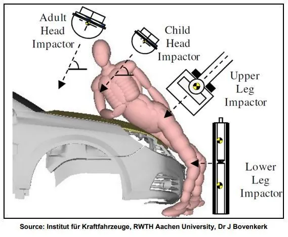
Vehicle designers usually focus on understanding the car-pedestrian interaction, which is characterized by the following sequence of events: the vehicle bumper first contacts the lower limbs of the pedestrian, the leading edge of the hood hits the upper thigh or pelvis, and the head and upper torso are struck by the top surface of the hood and/or windshield. Most pedestrian deaths occur due to the traumatic brain injury resulting from the hard impact of the head against the stiff hood or windshield. In addition, although usually non-fatal, injuries to the lower limb (usually to the knee joint and long bones) are the most common cause of disabilities. The hood of most vehicles is usually fabricated from sheet metal, which is a compliant energy-absorbing structure that poses a comparatively small threat. Most serious head injuries occur when there is insufficient clearance between the hood and the stiff underlying engine components. A gap of approximately 10 cm is usually enough to allow the pedestrian’s head to have a controlled deceleration and a significantly reduced risk of death. Most limb injuries occur due to a direct blow from the bumper and the leading edge of the hood. Wrap Around Distance (WAD) is the distance from the ground level to the end of the hood as shown in the image.
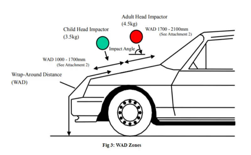
There are two main zones that are considered while the designing stage; the Child head impact zone (1000mm to 1700mm WAD) and the Adult head impact zone. (1700mm to 2100mm WAD). If the side reference line is on the fender, the WAD will be more and the impact zone will be less and vice versa.
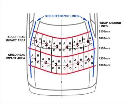
The hood panel should be designed in such a way that it diverges the impact forces during a collision away from the occupants inside the cabin. The forces should be damped properly to avoid or reduce the risk of injuries and death.
Components of Hood:
The components of the Hood includes Hinge, Latch and Reinforcements which are attached to the inner panel of the Hood. The basic definitions of these parts are given below:
Hinge: A hinge is a piece of metal, wood, or plastic that is used to join a door to its frame or to join two things together so that one of them can swing freely.
Latch: The hood latch helps to keep your hood closed. When the hood is closed, the latch slides over what is called a catch, and the spring covers the latch to keep it snug. When you pull the knob inside the car to open the hood, the hood latch cable opens the latch, allowing it to bypass the catch and open. There is, however, a second hood latch, to keep the hood from flying up if accidentally unlatched. That latch will need to be opened with your hand to get the hood fully open.
Reinforcements: The purpose of reinforcement is to provide additional strength for the hood where it is needed. When the latch and striker attached to the panel, the strength will be reduced in that area. To improve the strength in that area the reinforcement is added.
Latch Trajectory:
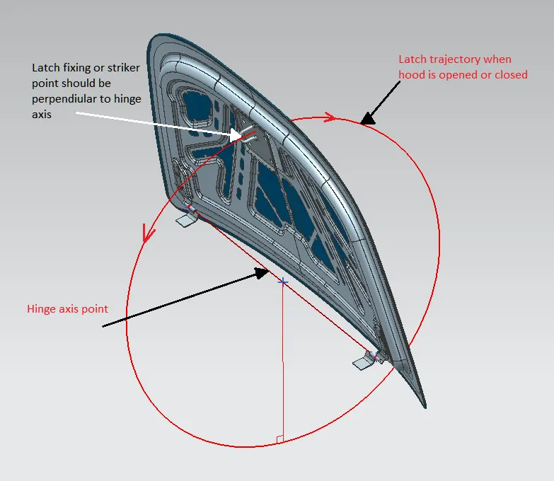
Latch Trajectory is the orbital path in which the latch should be positioned to the lock hole. The trajectory is drawn based on the reference of the Hinge joint central axis.
Mastic Data:
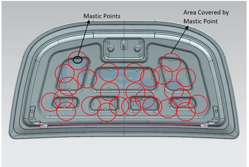
Mastic is common as an adhesive and sealant. A mastic sealant is a type of liquid sealant that cures in an elastic state, thus making it flexible while holding the bond of the surfaces that have attached. It adheres to just about any material making an all-purpose type of sealant. Wood, aluminium, glass, marble, and even duct board are all standard applications for mastic sealant.
Embossments:
Embossing is an operation used in making raised figures on the sheets, with corresponding relief on the other side. The process essentially involves drawing and bending the metal. The die set consists of a die and punch with the desired contours so that when the punch and die meet the clearance between them is the same as that of the sheet thickness. Embossing operation is generally used for providing dimples on sheets to increase their rigidity and for decorative sheet work used for panels in houses and religious places. Stretch forming operation is a relatively less severe operation.
Manufacturing Process:
The manufacturing process involves turning raw materials into finished products which are used for some purpose. The economics of the manufacturing operation is a very important consideration. To be viable in the modern environment, a product has to be competitively priced besides having functional and aesthetic appeal. There are different processes available for manufacture. These are classified as Casting Process, Forming Process, Fabrication Process, Material Removal Process.
Deep Drawing:
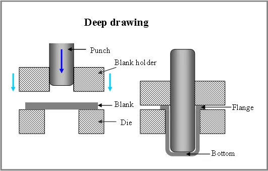
Drawing is the process of making cu[s, shells, and similar articles from metal blanks. Drawing when cup height is more than half the diameter is termed deep drawing. Ductile materials are easier to be drawn into deeper cups. In deep drawing, because of the radial flow of material, the sidewalls increase in thickness as the height is increased. There would be a slight thinning of metal at the bottom corners.
Hemming:
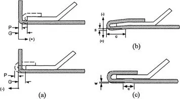
Hemming is a sheet metal forming process in which sheets are joined by bending it usually to 180 degrees. Automotive body panels and automotive parts such as deck lids, trunk lids, doors, hoods, and tailgates are forming by the hemming process.
Procedure:
Creating Hood Inner Panel:
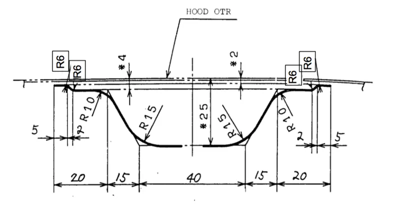
To create the Hood Inner Panel, the below input (i.e Master section) needs to be followed.
First, open the given model i.e, Hood styling surface in CATIA V5.
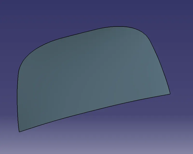
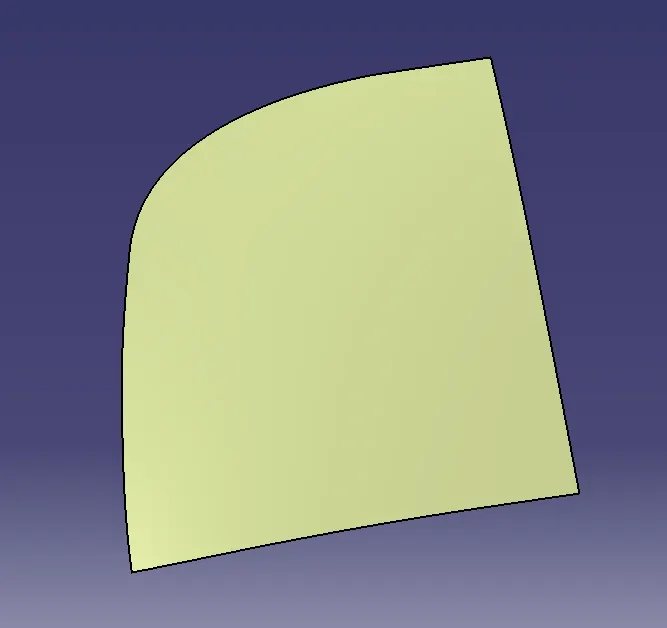
Extract the surface and split it using the YZ plane to get the half portion of the surface.
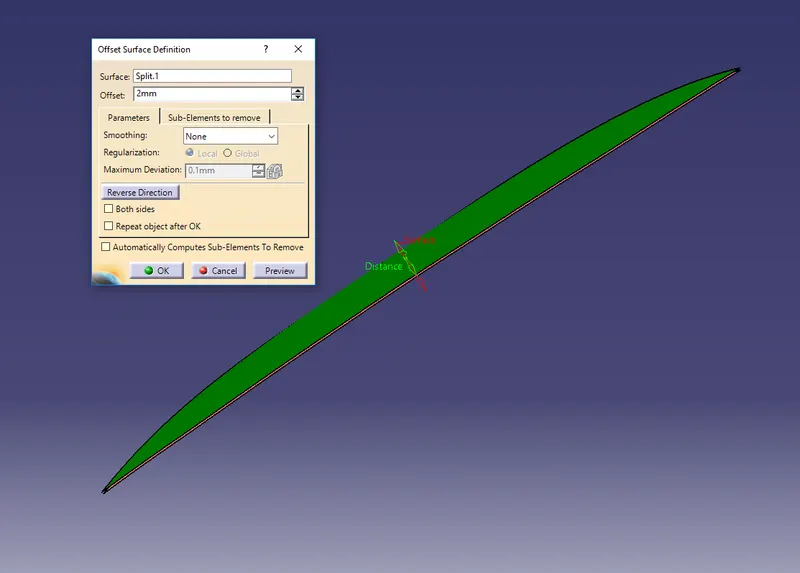
Now following the master section, offset the surface (split surface) to 2mm.
After offsetting the surface, use the boundary option to create boundaries of the surface and then using the parallel curve option, offset the boundary on the surface for about 20mm (15+5mm).
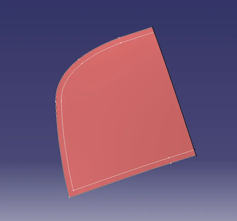
Note: Since the distance from the corner to the first edge is not given in the master section, we are assuming a value of 15mm.
Now split this surface with the boundary which we offset to get the first inner portion surface of the Hood.
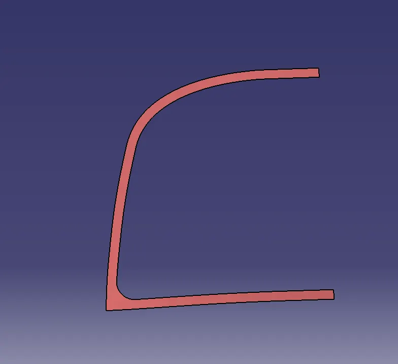
Similarly, we need to create all other inner portion surfaces for the Hood Inner Panel at different offset values by following the master section.
Offset the split surface (the main surface which we split with the YZ plane) to 4mm and again by extracting the boundary, offset it to 22mm (15+5+2mm) on the surface. Split the surface using this boundary and this will give us our second portion of the inner surface.
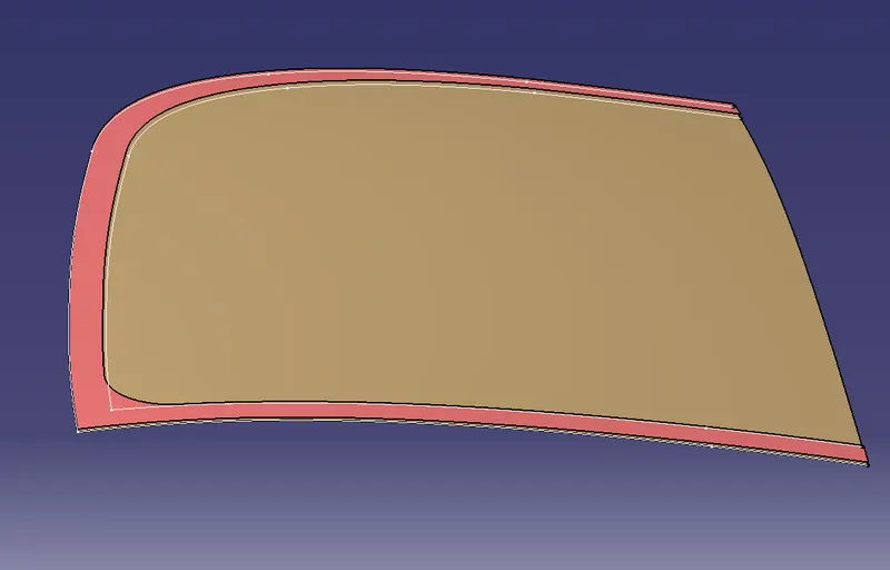
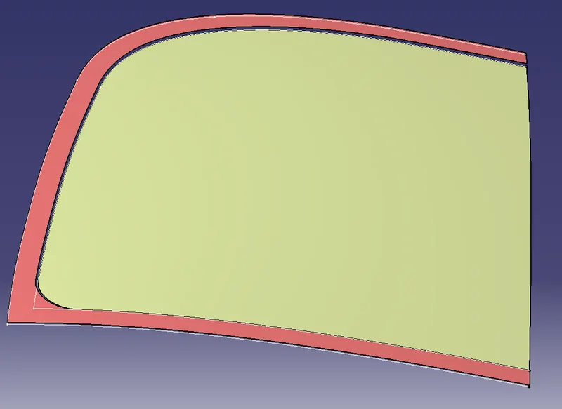
We also need to offset the boundary to 35mm (15+20mm) and split the second portion surface with it to get the inner edge of the surface.
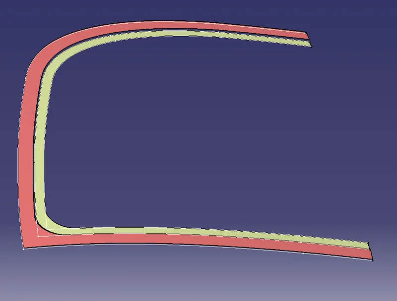
Create a surface between the first and second inner portion surfaces (by selecting inner edges) using the Blend or Multi-Section option.
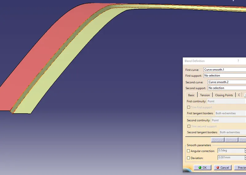
Now again offset the main split surface to 25mm and offset its boundary to 50mm (15+20+15mm) and split the surface. This will give us the third and final inner portion of the Hood Inner Panel.
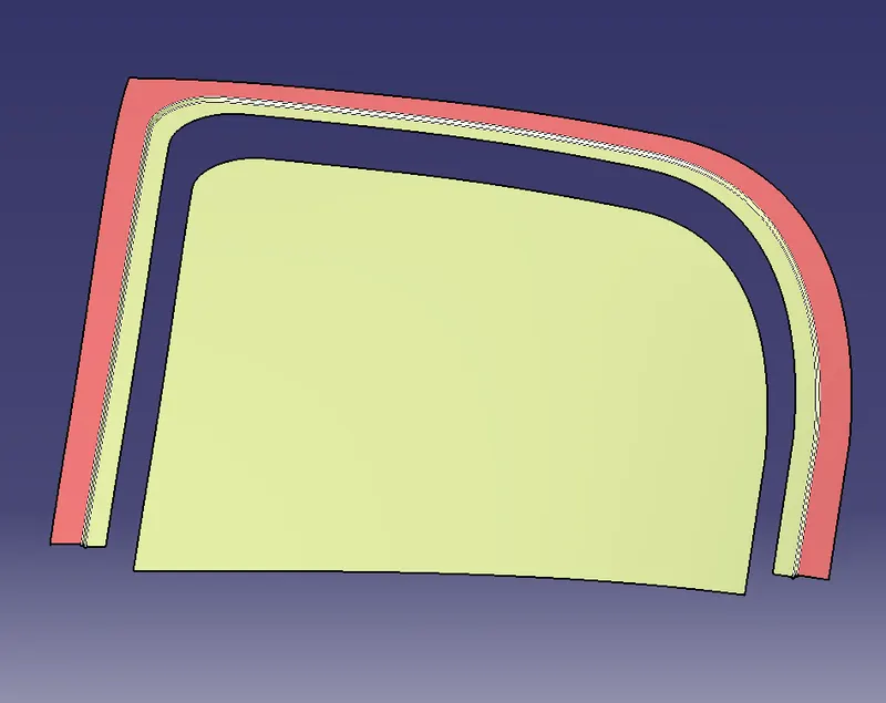
Similarly, create a surface between the second and third inner portion surfaces (by selecting inner edges) using the Blend or Multi-Section option and give the required fillets to the edges by following the master section.
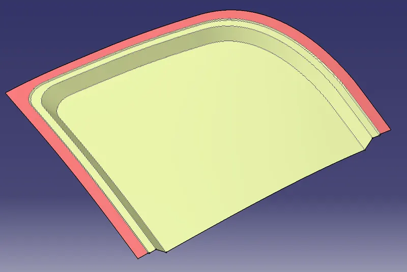
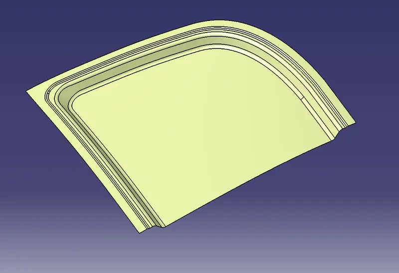
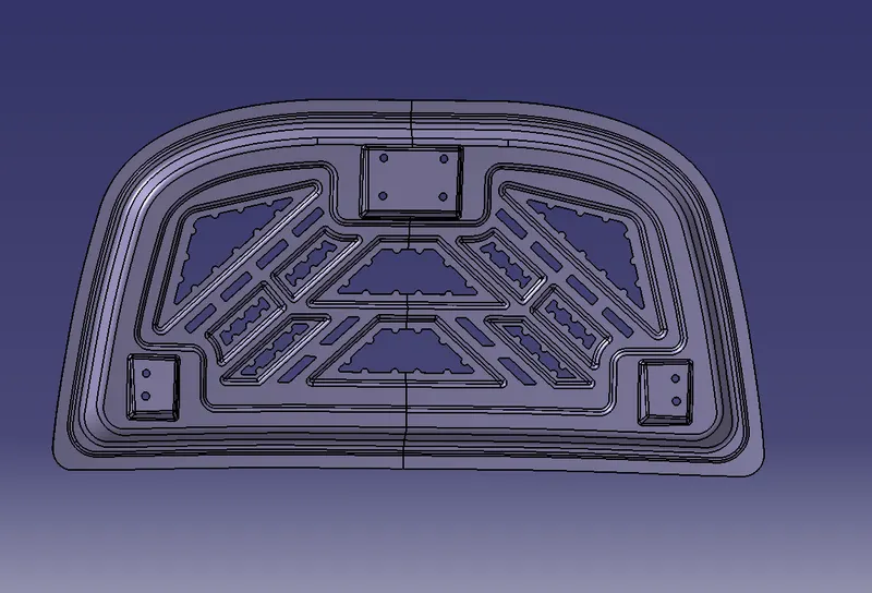
Now to create embossment, create a sketch (no specific dimensions is needed) and project this sketch on the Inner Panel surface.
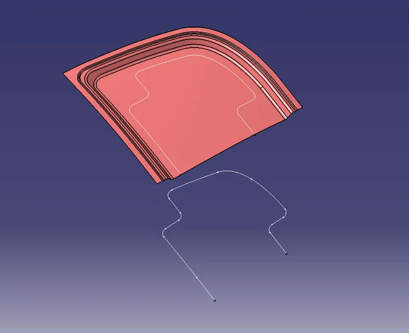
Split the surface with this projected sketch to get the cut out for the embossment.
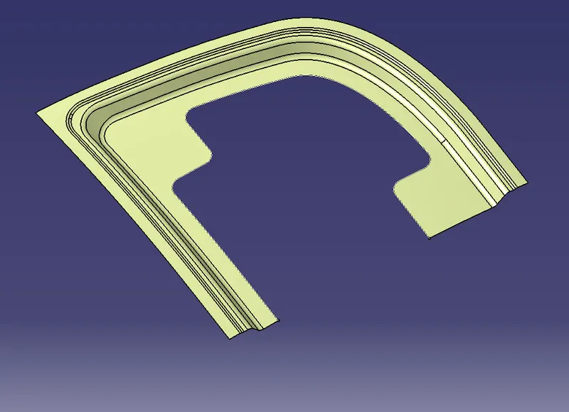
Using the boundaries of this cutout, sweep the surface with a draft value of more than 7 deg.
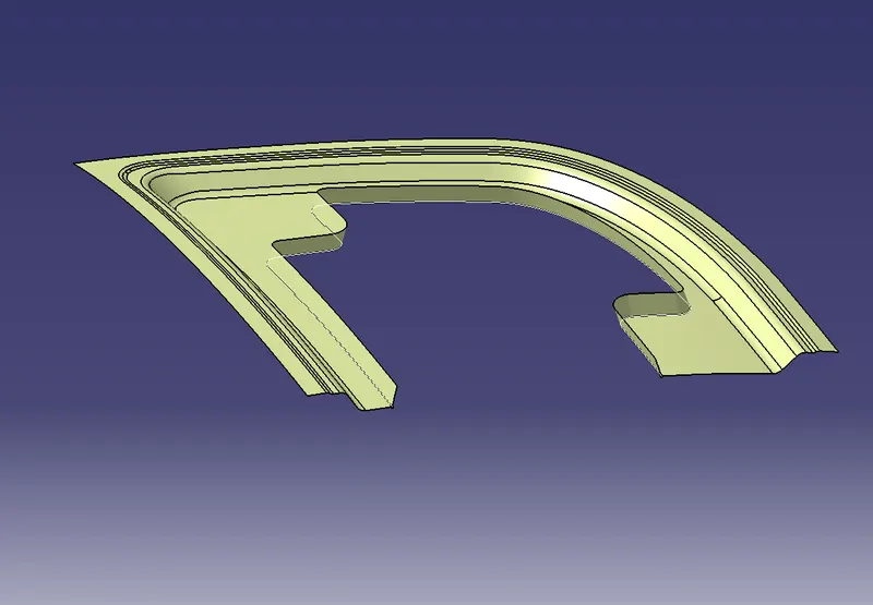
To create the base surface for the embossment, offset the main split surface with a value that can give the embossment a height of 5mm.
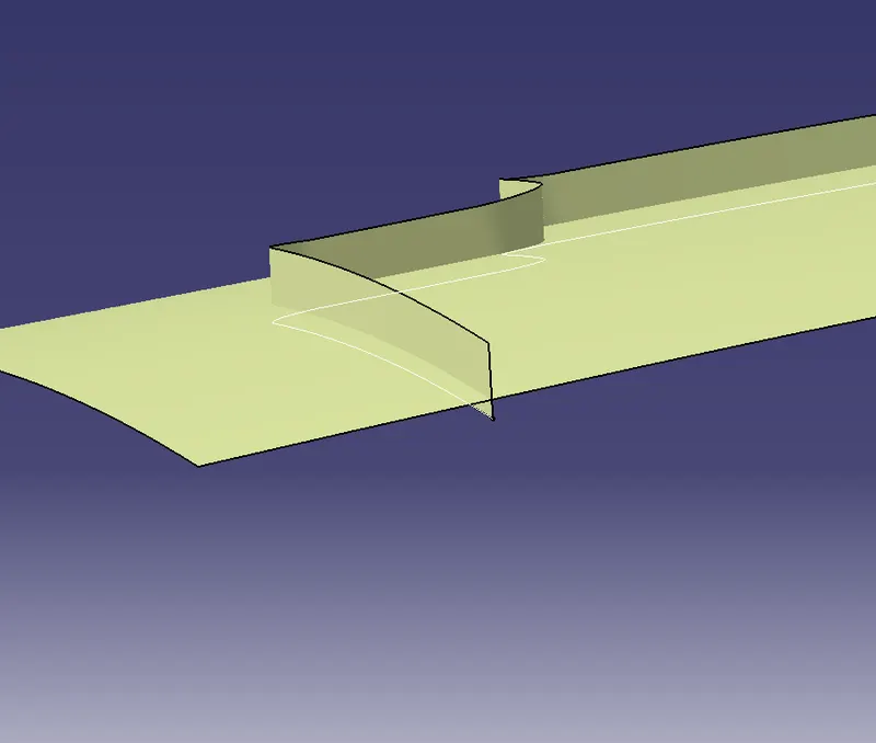
Now trim the sweep surface with the base surface of the embossment to get the final output.
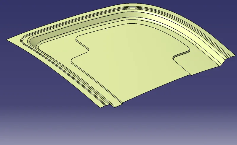
Necessary cuts are needed for the embossments and they should be in such a way that the stress in the body that develops during an impact should not affect the occupant heavily.
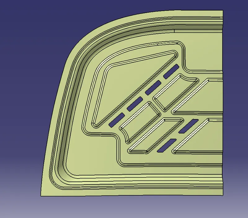
After creating the embossments, mastic points are to be included near the hole regions such that these points are used to make sure that there is no gap between the outer and inner panels.
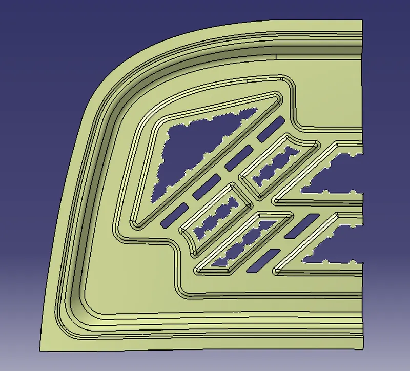
Now using the symmetry option create a surface on the other side. Join these surfaces and if there is a gap between the surfaces, we need to create a surface in between them.
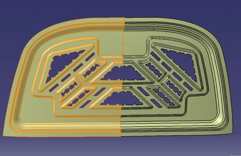
Note: A max of 0.003 merge value can be given while joining the surfaces.
Creating Hood Outer Panel:
To create the Hood Outer Panel, the below inputs needs to be followed.
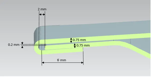
Using the main split surface, create the outer panel by first extrapolating it to 2.75mm.
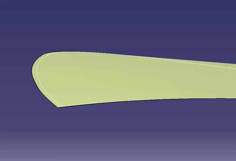
Now offset this extrapolated surface to 2.45mm and extract its boundaries.
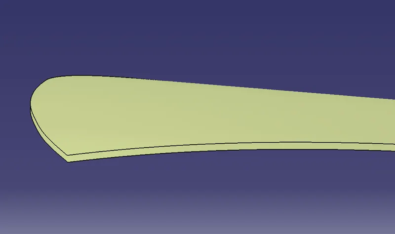
Using the parallel curve option, offset the boundary to 6mm and split the surface using it.
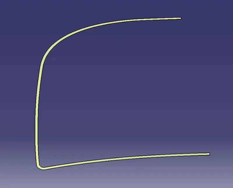
Create a surface between the extrapolated surface and split surface using the Blend or Multi-Section option. Join the Surfaces and give an edge fillet to them.
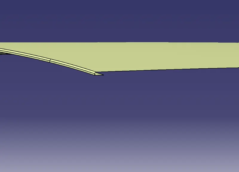
According to the requirement, we need to give 3mm cutouts at the hemming regions.
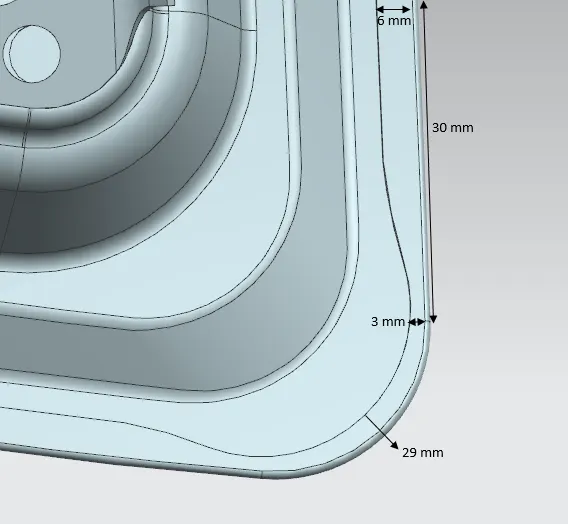
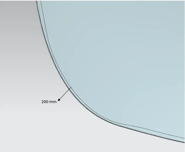
Extract & offset the boundary to 3mm and using spline create the cutouts of 3mm.
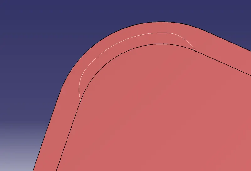
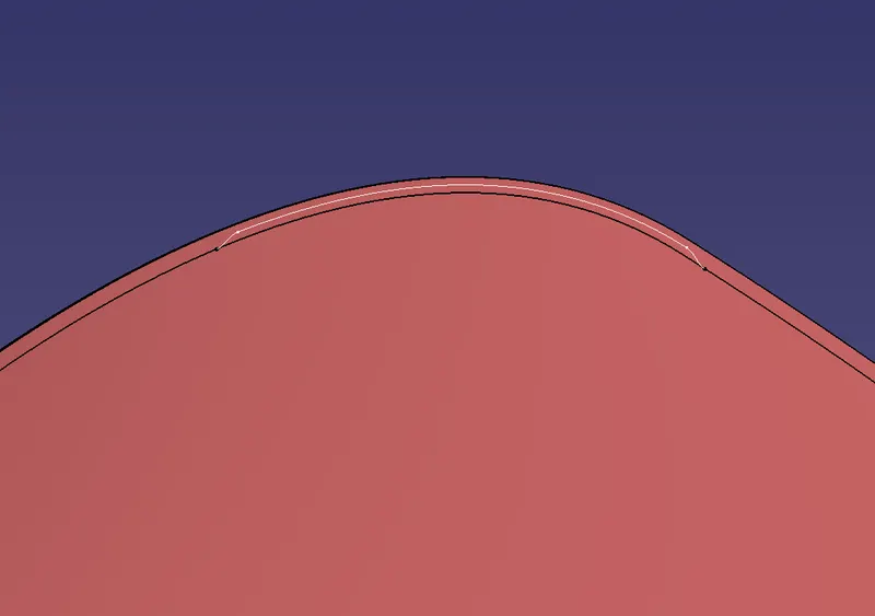
Project these cutouts lines on the surface and split the surface using it.
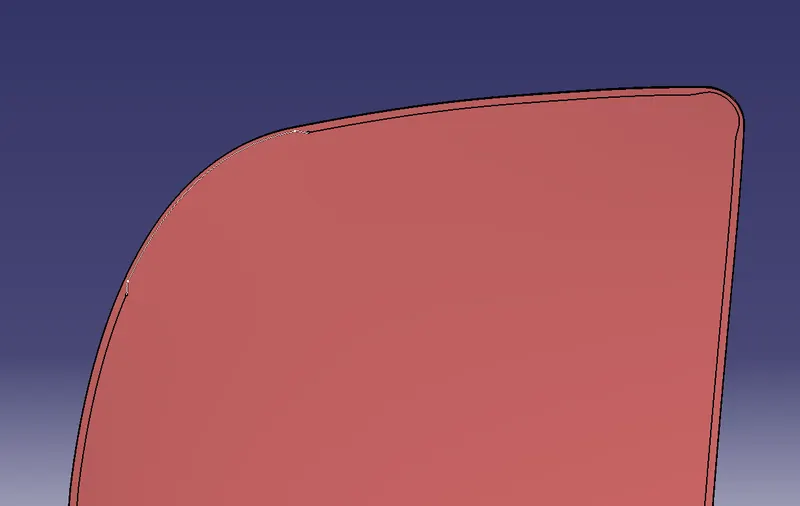
Using the symmetry option create a surface on the other side. Join these surfaces with a max merge value of 0.003mm.
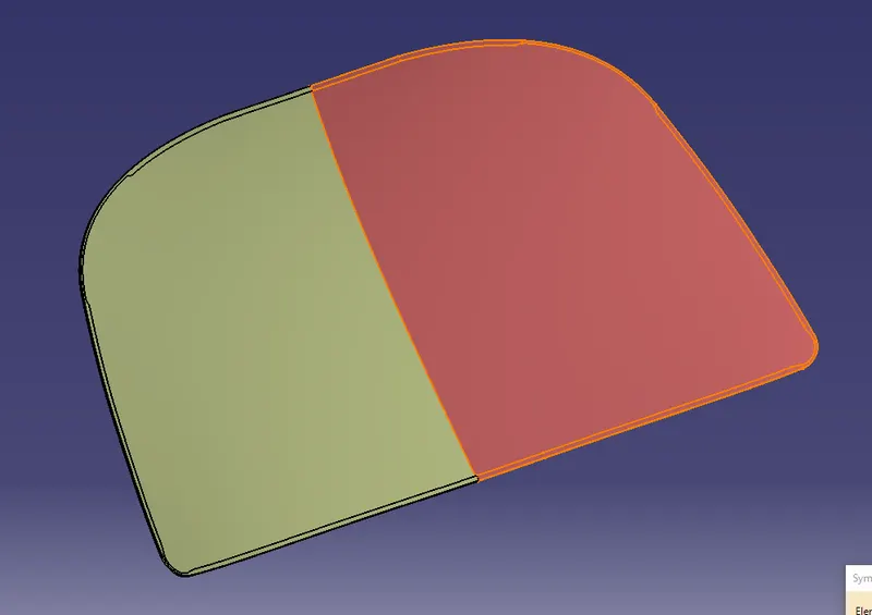
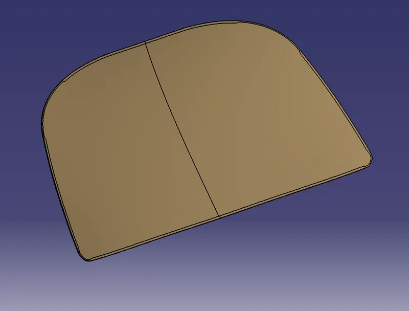
Create a solid body with a thickness of 0.75mm using thicken option in the part workbench.
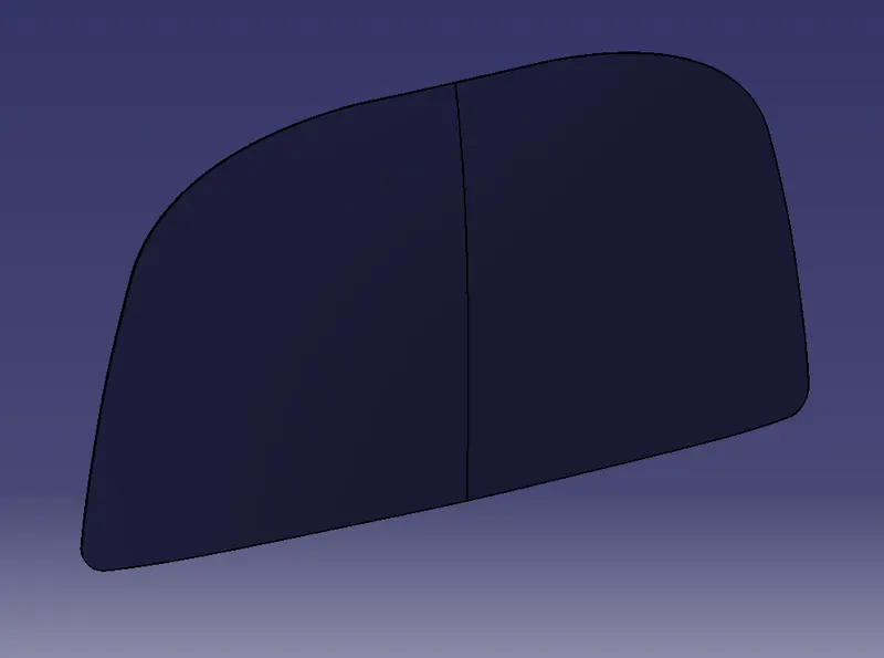
Creating embossment for Hinge:
To create the embossment for Hinge, use the Assembly workbench to adjust the Hinge Part near the Hood Part using the manipulate tool.
Now, go to the Hood Model part workbench and create a sketch using the Hinge such that the embossment area can cover the hinge part.
Once the sketch is created, project it to the surface and split the surface using it.
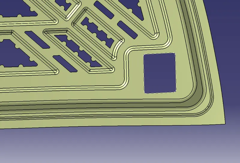
Use the Sweep option to create the surface with a draft value of more than 7 deg.
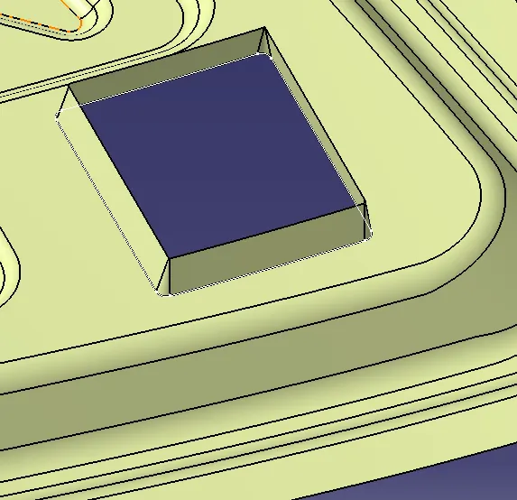
Now extract the lower surface of the hinge part and extrapolate it. Trim the sweep and extrapolated surface to get the final output.
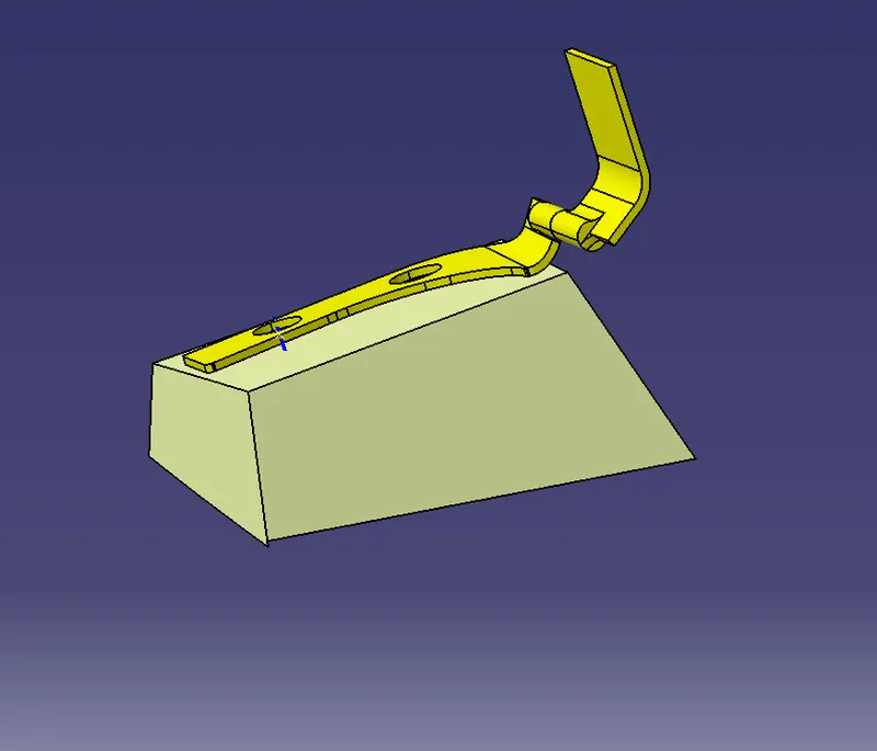
Mirror the Hinge Surface onto the other side and join these hinge with the main surface (Inner Panel).
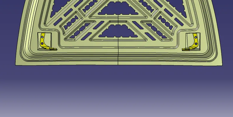
Create a point at the centre of the Hinge circle at both ends and create a line using the two points.
Create the middle point using the two points created and create a circle using the middle point created. The circle trajectory should be tangent to the latch part.
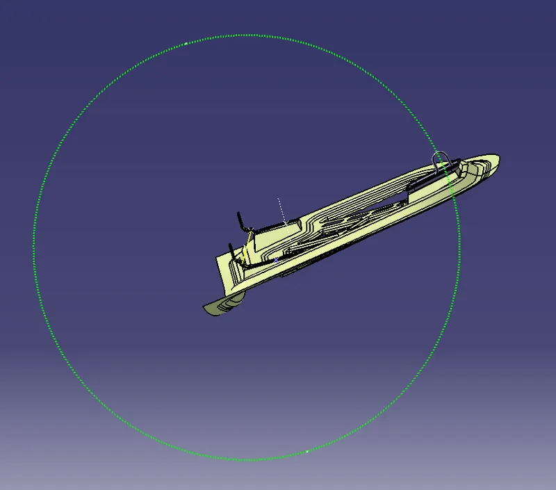
Creating embossment for Latch:
Creating embossment for Latch is similar to that of the hinge part but in this case, the latch part striker should be tangent to the circle.
Use the striker to create a sketch and project it to the surface and split it.
Now extract the lower surface of the striker part and extrapolate it.
Trim the sweep and extrapolated surface to get the final output.
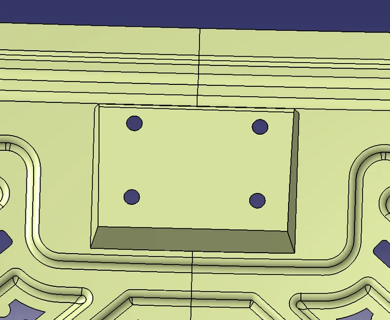
Finally, join this surface with the Inner Panel Surface and thicken it in the part workbench with a thickness value of 0.75mm.
Creating Reinforcements:
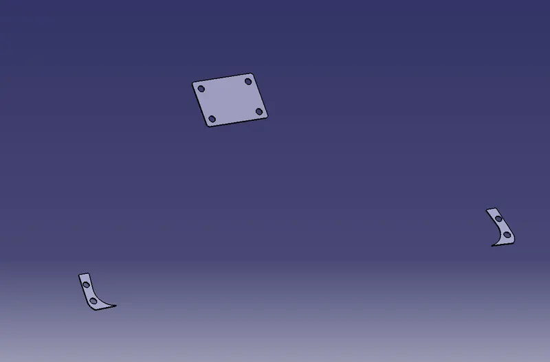
To create the Reinforcements, Go to the Assembly workbench, Click on the lower part of the Hinge and Latch surfaces and extract the surfaces.
Go to Part Workbench and Use the thick surface option to create a solid with a thickness of 1.5mm.
Assembling the components:
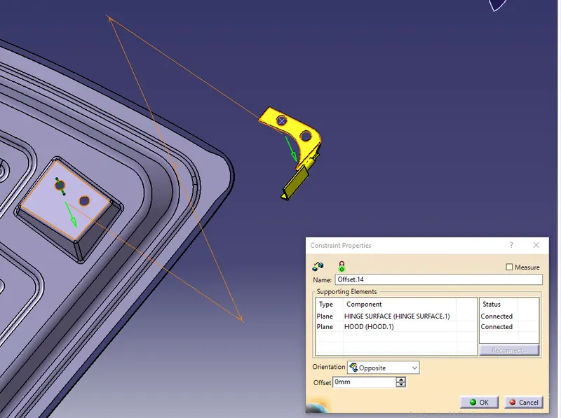
To assemble the components, Go to the Assembly Workbench and constraint the parts using offset constraints. Give an offset value of '0' by selecting the embossment surface of the hinge and the lower part of the hinge. A similar operation needs to be performed for constraining the Latch.
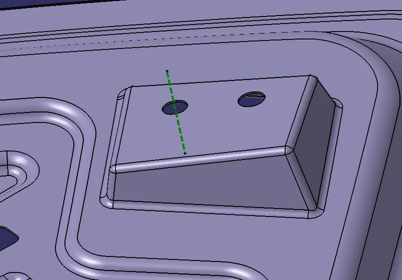
Create an axis at the centre of the holes of the latch and hinge embossment and their parts and coincide these axes with there respective parts.
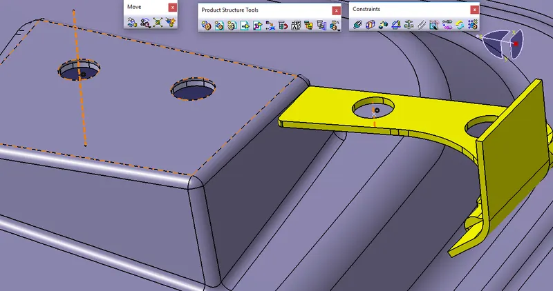
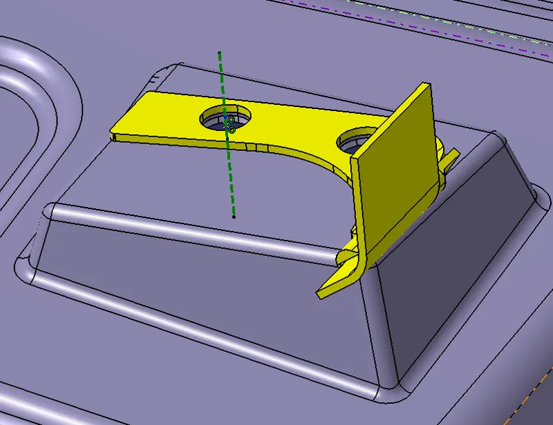
Use explode & update option to check if all the parts are assembled properly or not.
Result:
The design and development of the Hood inner panel, outer panel, latch, hinge and reinforcements is completed following the design parameters and also successfully assembled.
DRAFT ANALYSIS ON CAD MODEL:
The draft analysis of the hood inner panel was successfully performed with a minimum angle of 7 degrees with respect to the tooling direction.
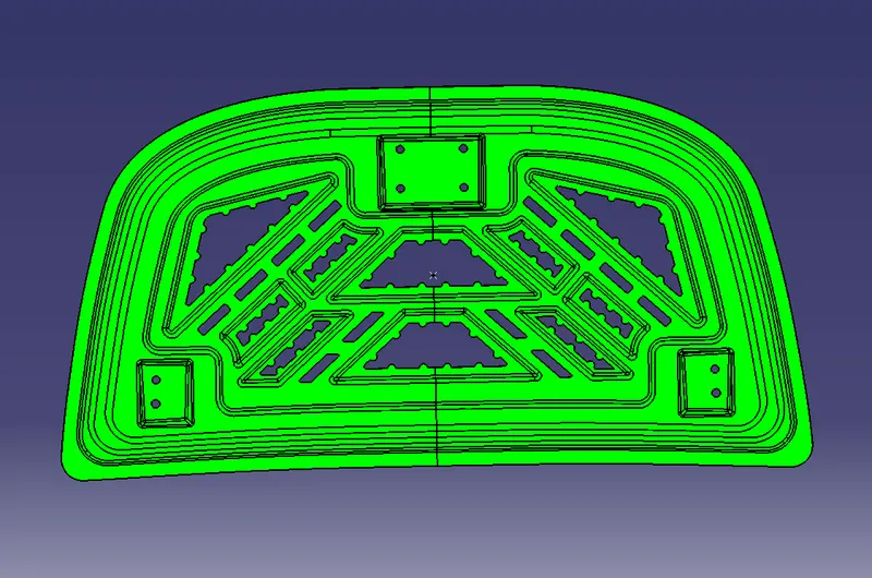
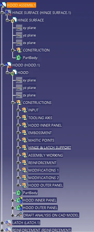
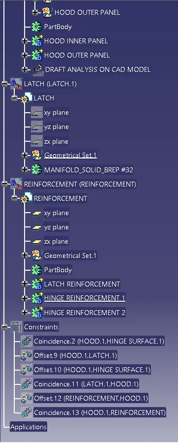
TREE STRUCTURE:
FINAL CAD MODEL: