Roof Crush Analysis - BIW of Neon Car
Aim:
To set up the case for ROOF CRUSH - BIW OF NEON car and successfully simulating while also plotting the graphs for the results obtained.
SOFTWARE:
HyperWorks 2020
USER PROFILE:
RADIOSS
OBJECTIVE:
The objective of the challenge is to follow the below-given steps:
Import
- Car
- Impactor
Transforms
- This will require (in order)
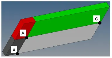
- A 180° rotation about the global z-axis with the point opposite to C as a base point
- A 25° rotation about the axis through axis AC
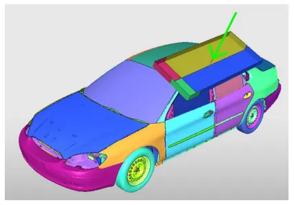
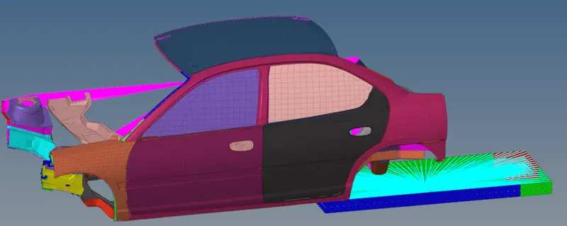
Reference image ( Full Vehicle Model )
Interfaces
- Create a Type 7 contact interface between the impactor and the car
- choose an appropriate stiffness definition
- choose an appropriate minimum gap
- change the coefficient of friction to 0.2
- choose the appropriate friction penalty formulation
- Save the data from the interface to the time history file.
Boundary condition
- keep the suspension shock tower nodes locked in Z.
Impactor Boundary Conditions
- The impactor assembly contains a spring attached for stability. Create a BCS collector to fix the free end of the spring.
- Create a moving SKEW to define the direction normal to the impactor’s face.
- Create a BCS collector to guide the master node of the impactor rigid body so that it is free to translate normally to the face of the impactor, but is fixed in all other DOFs.
Imposed Displacement
- Impose the velocity of the impactor starting from 0 mm/s at t = 0. The displacement of the impactor should be 200 mm @ 200 ms.
- Avoid abrupt changes in the acceleration of the impactor.
Setting up the control Cards in the engine file
- /ANALY card
- /DEF_SHELL card,
- /DEF_SOLID card, and
- /IOFLAG card
- /SPMD card
- /TITLE card
Engine File
- Solve for 200 ms
- Create an animation file every 0.0005 seconds
Include selected output in animation files:
- Elemental Energy
- Elemental equivalent plastic strain
- Elemental hourglass energy
- Elemental von Mises stress
- Nodal added mass
- Turn on parallel arithmetic
Solution and Results Post Processing
- Run the model
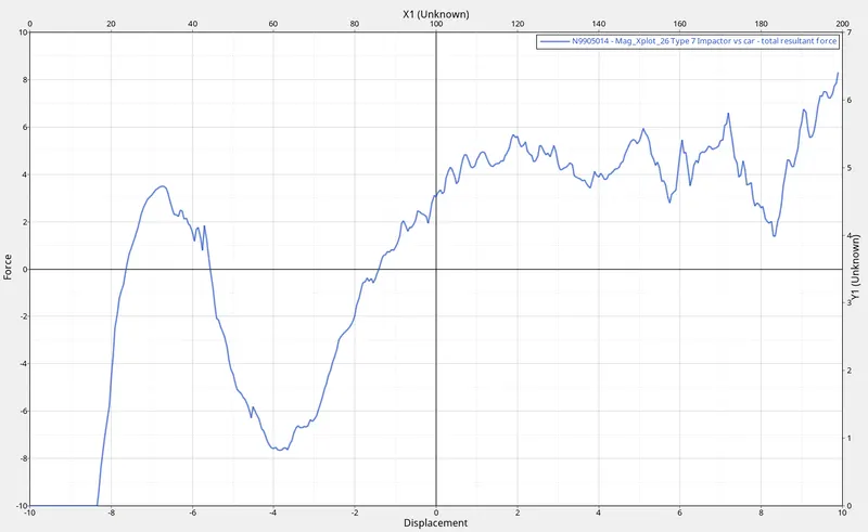
- Plot force vs. displacement. Check that the FMVSS 216 target load of 47,000 N (= 3 * GVW) has been met.
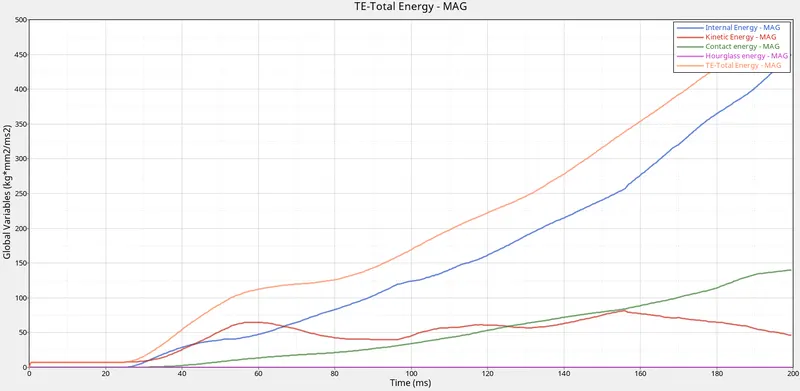
- Plot the energy vs. time curves
REFERENCE IMAGES:
PROCEDURE:
Importing the models:
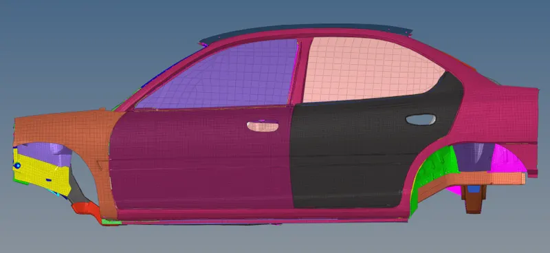
First import the car starter file (.rad) in HYPERMESH by going to menu bar > file > import > solver deck. Browse the file from the system and import it.
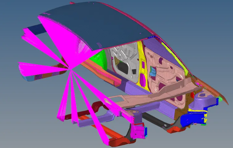
Now on the same graphical screen import another model i.e impactor. Follow the same steps as mentioned above to import the impactor.
Checking for the units:
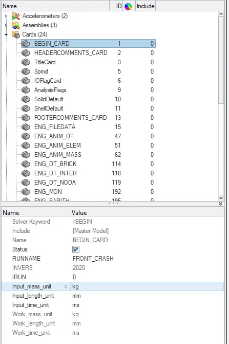
After importing the model, check for the units. In this project, we are following the [Kg mm ms] unit system. To change the unit system Go to Tab bar > Cards > Begin card.
Setting up an impactor location:
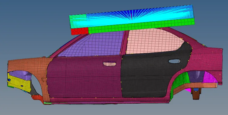
To set up the impactor location, we need to use rotate and translate options in HYPERMESH. First, we need to rotate the impactor and to perform this operation Go to Tools > Rotate > select all the elements of impactor > select the z-axis and base point as C (as shown in the reference image) > angle as 180° and click on Rotate +.

Now a 25° rotation about the axis through axis AC needs to be performed on the impactor by following the same procedure as mentioned above.
Now using the translate option move the impactor and place it in a position as shown in the reference image. To perform this operation, Go to Tools > Translate > select the axis > give magnitude value and click on Translate +.
Creating interfaces:
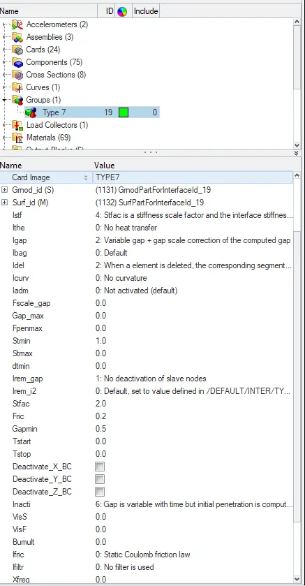
In this project we need to create two interfaces, one interface is for the self contact with the components of the car and the other will be for the contact taking place between the car & impactor. For both the contacts we will be using a Type 7 interface only. Now to create the interface, Go to Tab bar > Groups > right-click on it and create. Set the recommended properties of the Type 7 interface which is given below.
Note: Delete all the previous interfaces which are present under the groups.
Card image: Type 7
FOR CAR:
Gmod_id (S) (slave entities): select all the components of the car.
Surf_id (M) (Master entities): select all the components of the car.
FOR CAR & IMPACTOR:
Gmod_id (S) (slave entities): select all the components of the car.
Surf_id (M) (Master entities): select all the components of the impactor.
Istf: 4 - It is the gap for stiffness definition, it is the interface stiffness which is the minimum of the master and slave stiffness.
Igap: 2 - It is the gap option flag. Igap = 2 is Variable gap + gap scale correction of the computed gap.
Idel: 2 - It is the node and segment deletion flag. When a 4-node shell, a 3-node shell or a solid element is deleted, the corresponding segment is removed from the master side of the interface. It is also removed in case of explicit deletion using the Radioss Engine keyword /DEL in the Engine file.
Additionally, non-connected nodes are removed from the slave side of the interface.
Stmin: 1 - It is the minimum stiffness value that can be used only if Istf value is not equal to 1.
Irem_gap: 1 - The option Irem_gap is used to deactivate slave nodes that are close to elements. But in this case, since we put the value as 1 that means there is no deactivation of slave nodes.
Stfac: 2 - Stiffness scale factor applied to the master side of the interface (if Istf is not equal to 1).
Fric : 0.2 - Coulomb friction
inacti: 6 - Deactivation flag of stiffness in case of initial penetrations. But in this case, the value is set to 6 which means the gap is variable with time but initial penetration is computed.
Gapmin: 0.5 - Minimum gap for impact activation.
Iform : 2 - Stiffness (incremental) formulation.
NOTE:
The only difference between the two interfaces is that in the first interface (which is for self contact) we are just selecting the components of the car in both master and slave while in the second interface ( CAR & IMPACTOR ) we are selecting the components of the car as slave and components of impactor as a master.
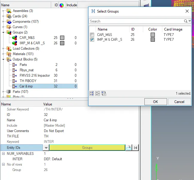
Now we need to call the CAR & IMPACTOR interface in the output block. To perform this operation Go to Tab bar > under model browser > right-click on output block and create > name the card > under Entity IDs select the car and impactor interface.
Applying Boundary Conditions:
The boundary condition for shock towers:
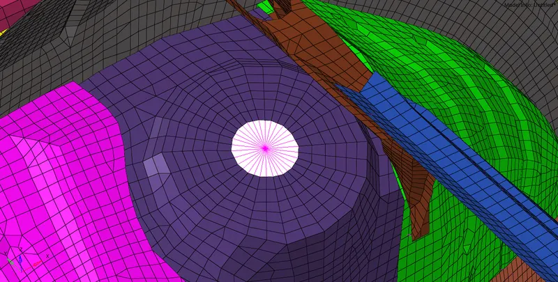
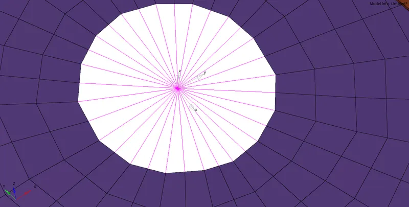
There are three shock towers in the model for suspension at 3 different locations. These shock towers should be locked in the z-axis so that they cannot move in the z-direction. For this, we first need to provide a rigid body connection to all the nodes of shock towers and we also need to create a SKEW to define the local coordinate system. To create a rigid body, Go to the main menu page > 1D > rigids > select the nodes and create. Now create a skew at the centre node of the rigid body, Go to Tab bar > under solver browser > right click and create > SKEW > MOV. select the origin node (N1), Axis node (N2) and plane node (N3) and this will create a local coordinate.
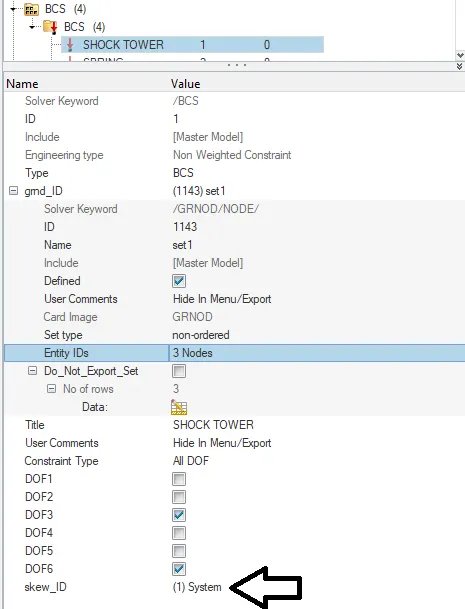
Now create Boundary condition for shock towers, To perform this operation Go to Tab bar > under solver browser > right click and create > BOUNDARY CONDITIONS > BCS. Name it as shock towers and under Entity IDs select the 3 centre nodes of rigid bodies and select the SKEW system (which we have created for shock towers) under Skew_ID. To keep the suspension shock tower nodes locked in Z - DIRECTION, select only DOF 3 and DOF 6 boxes.
The boundary condition for impactor and spring:
Spring:
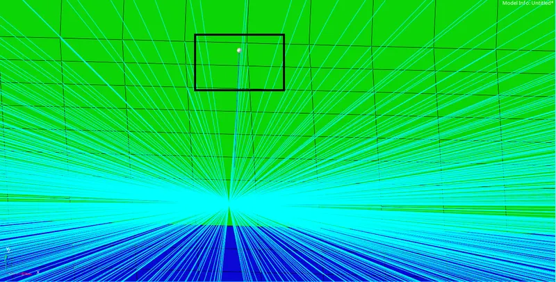
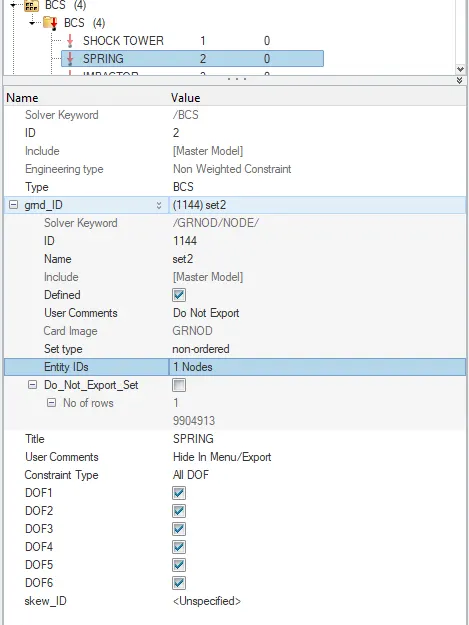
The impactor assembly contains a spring attached for stability. Create a BCS to fix the free end of the spring. To fix the free end of the spring just select the free end node of the spring under Entity IDs and select all the DOF.
Note :
create a separate BCS collector for spring. The procedure for creating the BCS is the same as mentioned in “Boundary condition for shock towers”.
Impactor:
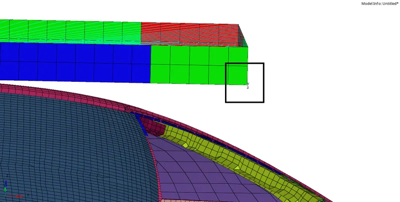
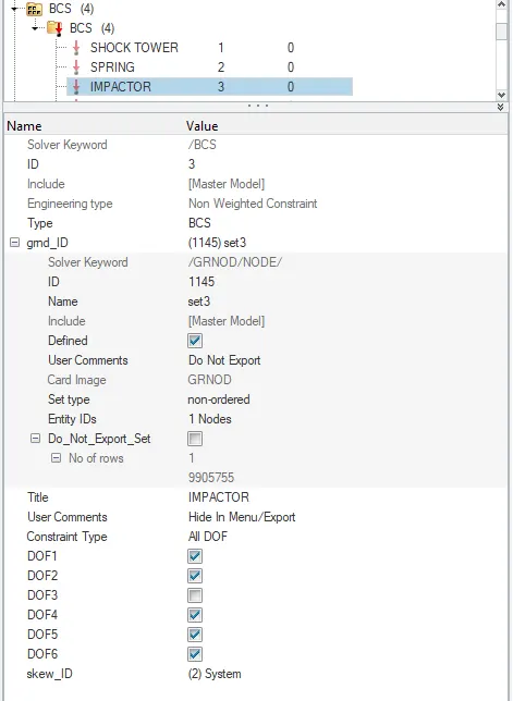
To create a BCS for the impactor we also need to create a skew to define the direction normal to the impactor’s face. The procedure for creating the SKEW & BCS is the same as mentioned in “Boundary condition for shock towers”. But while selecting the Skew_ID make sure to select the SKEW system which we have created for impactor.
DOF should be locked in all the directions except DOF 3 so that it is free to translate normally to the face of the impactor but it is fixed in all other DOFs.
Note:
We can also create a BCS for rigid bodies as a precautionary measure. Lock all the DOFs in BCS for rigid bodies.
Applying imposed displacement:
To apply imposed displacement to the impactor, we first need to plot a velocity/displacement curve. The velocity of the impactor starting from 0 mm/s at t = 0 and the displacement of the impactor should be 200 mm @ 200 ms.
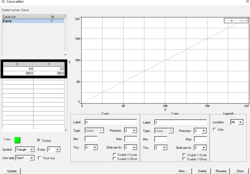
To plot the curve, Go to the Tab bar > under the model browser > right click and create > curve. A new dialogue box will pop up on the screen, click on new and name the curve, give X and Y coordinate values as (0,0) and (200,200) respectively and click on update.
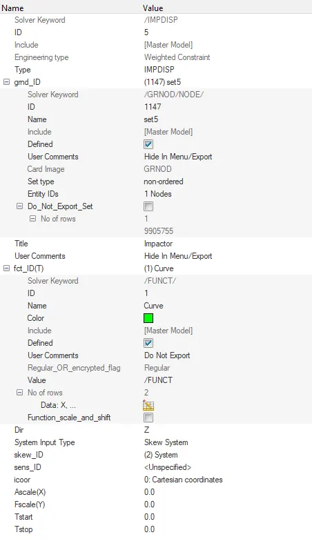
Now create imposed displacement by going to Tab bar > under solver browser > right click and create > BOUNDARY CONDITIONS > IMPDISP. Right-click on grnd_ID and create, under Entity IDs select the node at the fixed end of the spring ( that is at the centre of the impactor) and in the fct_ID select the curve which we have plotted. Select the SKEW (which we have created for impactor) under skew_ID and give the Dir as Z.
Setting up the control Cards in the engine file:
For the impactor, we only get a starter file. So to run the file to its fullest the Engine file should be created but to create the engine file, we don’t have the prerequisite data to create a new one.
The engine file can be copied from any previously created engine file. The file name should be renamed with the same name as the Starter file. Now, open the Engine file and change the name to the same name as the file name and save the file.
Now Import the model again and check that all the data cards are installed in it.
Penetration and intersection check:
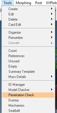
To check the penetrations, Go to menu bar > Tools > Penetration check.
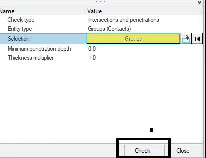
In the entity editor, click on the selection and under groups, select the type 7 contacts that we have created. In the Tab bar, we can view if there are any penetration and intersection in the model. After running the check, we can see that there is no penetration and intersection in the model.
Checking for errors:
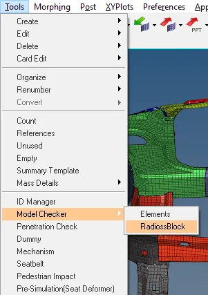
To avoid any kind of problems during simulation, we need to perform a check for errors. To perform this operation Go to menu bar > Tools > Model Checker > RadiossBlock. In the tab bar, a new browser will open, right-click on ERROR and run it.
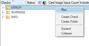
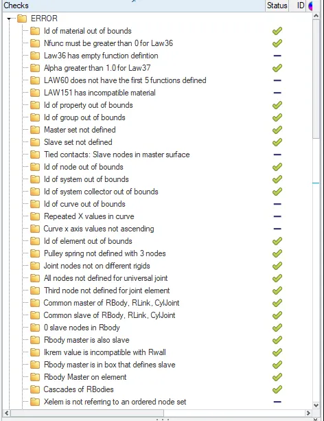
If there will be any errors present in the model then they will be highlighted with a cross mark. Clear the errors if there are any (currently there are no errors in the model).
Applying Time-step and run-time value:
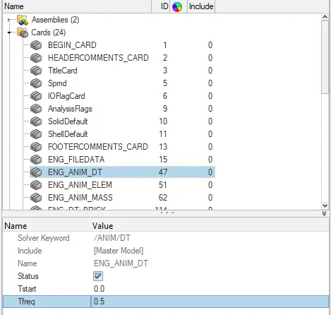
To apply the time step value, Go to Tab bar > cards > ENG_ANIM_DT. Change the Tfreq value to 0.5
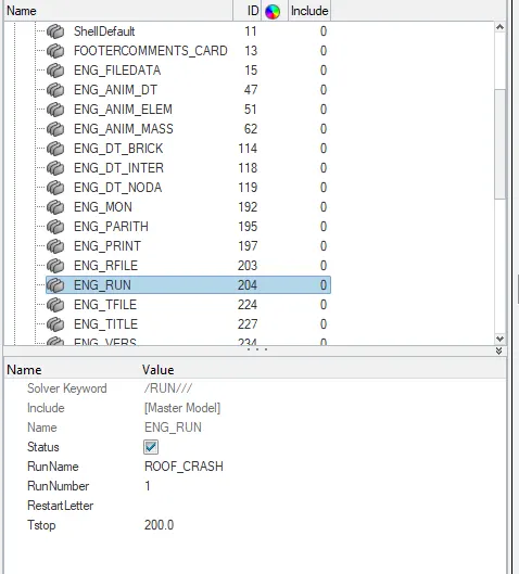
To apply the run-time value, Go to Tab bar > cards > ENG_RUN. Change the Tstop value to 200.
Errors faced and the steps to solve them:
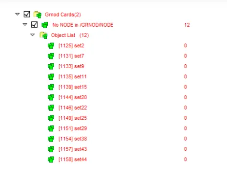
The final part of any simulation is checks and bug fixes during and after simulation. The only errors which we faced after setting up the simulation case were empty sets. While creating the Center of gravity (COG) point these sets may get created and it can be deleted. Though while checking the errors through the model checker in Hypermesh it won’t show the error of empty sets but while checking for errors in HyperCrash these errors can be found and deleted easily.
To run the model checker in HyperCrash, first, export the set up a case file and open it in HyperCrash. To open HyperCrash from the HyperMesh window, Go to menu bar > Applications > HyperCrash (select the unit system and run). This will open the HyperCrash window. Import the rad file (exported file from HM). Now to run the model checker in HyperCrash Go to menu bar > Quality > Model Checker > Run. Delete the empty sets and again export them. Now to run the simulation, open this file in Hypermesh and make sure to delete the unsupported cards. These unsupported cards are created by HyperCrash while exporting the file and it doesn’t make any change in the model.
Running the simulation:
After completion of all the tasks on the model, run the simulation and save it in a separate folder. To run the simulation, Go to the main menu page > Analysis > Radioss. Click on "save as" to change the file directory. Tick the box of include connectors and under the options tab, type the value as -nt 4 and click on Radioss to run the simulation.


Once the simulation is started, HYPERMESH will popup a box in which it will show the simulation process.
After the simulation run is completed, a message will show on the popup screen as the job is completed.
All the files which were generated during the simulation run such as the .h3d file, T01 file, starter file, engine file, etc will be stored in the input file directory.
Viewing Animation:
To view the animation, open HyperView. To perform this operation, Go to the Toolbar and from the client selector open HyperView and update the animation file (.h3d) in it. Select this file from the directory folder (the new folder which we created for the input file directory). After updating it click on apply to view the animation.


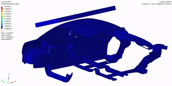
Now click on the play button to view the animation. To get plastic strain, von mises stress and nodal mass outputs in the animation file, follow the below steps.
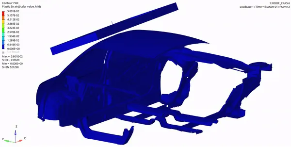
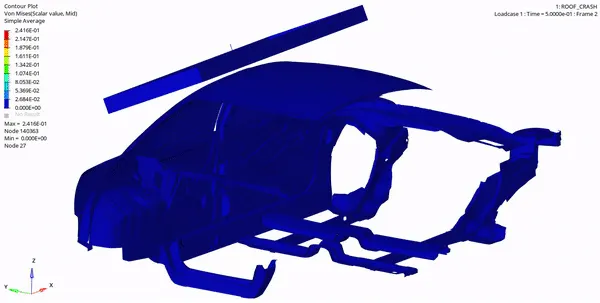
In the tools panel, select contour > in the result tab, select Plastic Strain (s) > click apply. The procedure to apply the von mises stress and nodal mass are the same as mentioned above.

Plastic Strain Animation:
Von Mises stress Animation:
Nodal Mass Animation:
Turning on parallel arithmetic:
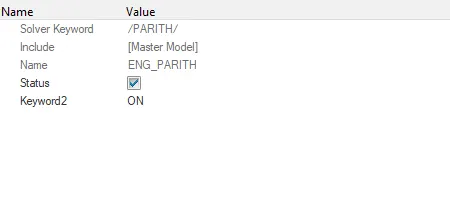
The PARITH card is checked and made sure it is kept ON.
To check the card, Go to tab bar > model browser > cards > check ENG_PARITH > keyword2 > ON.
Plotting the Graphs:
To plot the graphs, open HyperGraph 2D. To perform this operation, Go to the Toolbar and from the client selector open HyperGraph 2D and update the time history file (TO1) in it. Select this file from the directory folder (the new folder which we created for the input file directory).
FORCE VS DISPLACEMENT GRAPH:
Checking FMVSS 216 target load:
To check the target load of FMVSS 216, first, check the initial mass of the car. To check the mass Go to menu bar > Tools > Mass details. The initial mass of the car is 159.744kg.
According to FMVSS specified strength to weight ratio required a resistance force of 3 times the GVW to withstand the roof crash.
So in our case, the total weight of the car is 159.744 Kg. Then the total resistance force or target load will be,
I.e Target load = 3*9.81*159.744 = 4701.26 N
The initial mass of our car is only 1567 N which is not enough to resist the impactor force,
So to make the car roof withstand this impactor force we have to add mass to the vehicle body to make it more durable and stable during the roof crash.
ENERGY VS TIME GRAPH:
OBSERVATIONS:
From the animation, it can be observed that the car roof is not able to withstand the force acted by the impactor. This is because the total mass of the car is low and it was not able to meet the FMVS target load.
To make the car roof withstand this impactor force we have to add mass to the vehicle body to make it more durable and stable during the roof crash.
From the Force vs Displacement graph, it can be observed that the force is getting fluctuated with the displacement as the simulation is carried on. These fluctuations maybe because of the vibrations which were produced during the impact on the car roof.
More stresses are being generated at the point of impact which can be observed from the animation. Plastic strain animation shows that more deformation is taking place at B pillar this is because of the sudden impact on it by the impactor.
Hourglass energy is constant during the whole simulation.
Contact energy started to increase after 40ms, this is because the body is changing its shape very drastically during the crash which results in the elements getting penetrated causing the contact energy to rise.
PHRASES USED:
Below we have briefly discussed the important phrases which we have been used in the above procedure.
FMVSS:
FMVSS 216, Roof Crush Resistance, establishes strength requirements for the passenger compartment roof of passenger cars, multipurpose passenger vehicles, trucks and buses with a GVWR of 2722 kilograms or less. The purpose of the standard is to reduce deaths and injuries due to the crushing of the roof into the passenger compartment in rollover accidents.
Gross Vehicle Weight (GVW):
The gross weight of a vehicle (GVW) is the weight of the empty vehicle plus the weight of the maximum payload that the vehicle was designed to carry. In cars and small light trucks, the difference between the empty weight of the vehicle and the GVW is not significantly different (1,000 to 1,500 lbs). The largest trucks and tractor-trailers, however, have a payload capacity share of 200%, which means they can carry 200% of their empty weight. The medium-sized trucks (truck classes 3-6) have payload capacity shares between 50% and 100%.
Von Mises stress:
Von Mises stress is a value used to determine if a given material will yield or fracture. It is mostly used for ductile materials, such as metals. The von Mises yield criterion states that if the von Mises stress of a material under load is equal or greater than the yield limit of the same material under simple tension then the material will yield.
Boundary Condition:
A Boundary condition is a kinematic condition in which the velocity on a node’s degree of freedom is set to zero. There are six degrees of freedom at a node that can be constrained. A DOF is free if the code is set to zero (Box unselected) and fixed/locked if set to 1 (Box selected).
Imposed Displacement:
Imposed displacement defines nodal translational &/or rotational degrees of freedom that is defined to move according to function. Imposed displacement are the conditions that have been applied to the nodes irrespective of what is the condition of the body. It is very rigid just like a rigid wall. It won’t change and impose the conditions, no matter what the state of the model is. It follows the displacement versus time curve defined by the fct_ID.
Rigid Body:
A rigid body constrains a set of nodes to move together with no relative motion and can be used to simplify the modelling of non - deformable objects. It is defined by a set of slave nodes and a master node.
/ANALY card:
Defines the type of analysis and sets analysis flags.
If the parallel arithmetic flag is set ON, the same numerical results will be obtained irrespective of the number of processors used.
This card is read-only once. Only the first card /DEF_SHELL written in the model is used. The other card /DEF_SHELL is ignored.
/DEF_SHELL card
This keyword is used to set default values for certain parameters in all shell properties, but options could still be changed in each property set input, and in this case, the latter will prevail.
/DEF_SOLID card
This keyword is used to set default values for certain parameters in all solid properties and thick shells. The default values defined here will be overwritten by any values entered on the individual property input.
This card is read-only once. Only the first card /DEF_SOLID written in the model is used. The other card /DEF_SOLID is ignored.
/IOFLAG card
Describes the input-output flags.
Run#: Radioss run number (four digits) from 0000 to 9999.
/SPMD card
Sets SPMD parameters for Hybrid Massively Parallel Program (HMPP) computation.
/TITLE card
Describes the title.
The title must not start with a forward slash ( / ).
BIW:
Body in white simply called BIW is a manufacturing stage in automotive industries where all the components of a car body (before painting), barring moving parts (e.g., hoods, fenders, etc.), trims (e.g., glass, seats, etc.), or chassis subassemblies, have been welded together. All these sheet metal components are welded together to form a vehicle structure.
INTERFACES:
Interfaces are defined to model how parts interact when they come into contact with each other. In this project, we are creating a Type 7 interface.
Type 7 interface:
Type 7 interface is a node to surface type of contact. It is a general-purpose contact and is used to simulate all conditions. It provides a cylindrical gap area around the edges which makes it more accurate. The main advantage of interface type 7 is that the stiffness is not constant and increases with the penetration preventing the node from going through the shell mid-surface.
RESULT & CONCLUSION:
Below mentioned values were noted at the end of the simulation.
ENERGY ERROR: -16.4%
MASS ERROR: 0.4718E-01
TOTAL NUMBER OF CYCLES: 200001
TOTAL SIMULATION TIME: 9066.53s
The case for ROOF CRUSH - BIW was set up successfully and the simulation for the same was run in HyperMesh without any errors