Final Project: Design of an Electric Vehicle
AIM - To design an electric vehicle using MATLAB and SIMULINK.
INTRODUCTION -
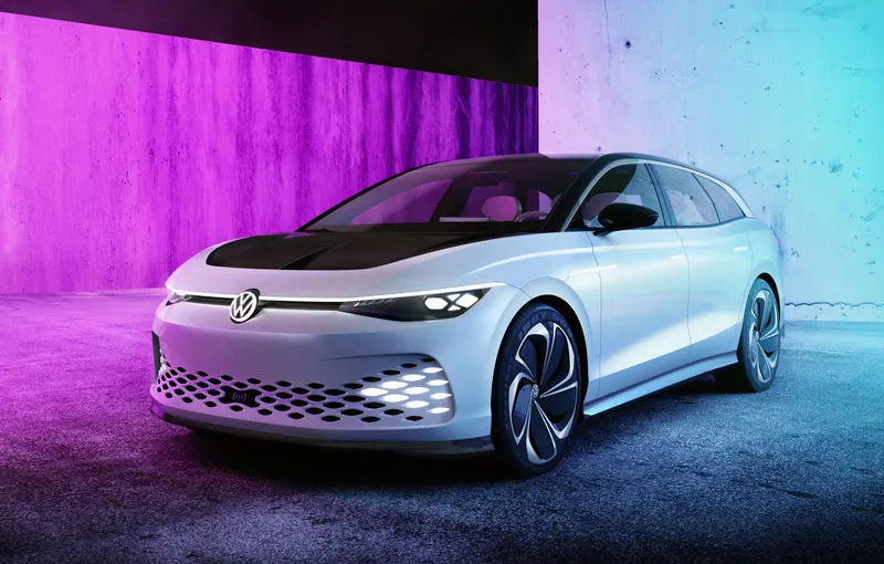
An Electric vehicle (EV) is a vehicle that uses one or more electric motors or traction motor for propulsion. An electric vehicle may be powered through a collector system by electricity from off-vehicle sources or maybe self-contained with a battery, solar panels, fuel cells or an electric generator to convert fuel to electricity. EVs include, but are not limited to, road and rail vehicles, surface and underwater vessels, electric aircraft, and electric spacecraft.
EVs first came into existence in the mid-19th century, when electricity was among the preferred methods for motor vehicle propulsion, providing a level of comfort and ease of operation that could not be achieved by the gasoline cars of the time. Modern internal combustion engine have been the dominant propulsion method for motor vehicles for almost 100 years, but electric power has remained commonplace in other vehicle types, such as trains and smaller vehicles of all types.
Commonly, the term EV is used to refer to an electric car. In the 21st century, EVs have seen a resurgence due to technological developments, and an increased focus on renewable energy, and the potential reduction of transportation's impact on climate change and other environmental issues. project drawdown describes electric vehicles as one of the 100 best contemporary solutions for addressing climate change.
Terminology - Electric cars are a type of electric vehicle (EV). The term "electric vehicle" refers to any vehicle that uses electric motors for propulsion, while "electric car" generally refers to highway-capable automobiles. Low-speed electric vehicles, classified as Neighbourhood electric vehicles (NEVs) in the United States, and as electric motorised quadricycles in Europe, are plug-in electric-powered microcars or city cars with limitations in terms of weight, power and maximum speed that are allowed to travel on public roads and city streets up to a certain posted speed limit, which varies by country.
While an electric car's power source is not explicitly an on-board battery, electric cars with motors powered by other energy sources are typically referred to by a different name. An electric car using solar panels as a power source is a solar car, and an electric car powered by a gasoline generator is a form of hybrid cars. Thus, an electric car that derives its power from an on-board battery pack is a form of battery electric vehicle (BEV). Most often, the term "electric car" is used to refer to battery electric vehicles, but may also refer to plug-in hybrid electric vehicle (PHEV).
Electrified vehicles are classified as:
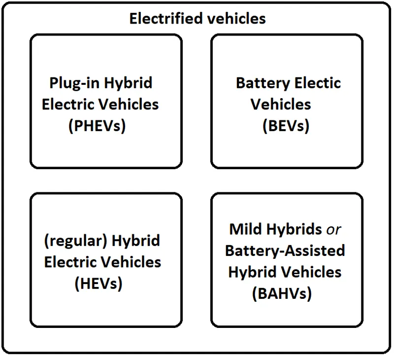
1) Plug-in Hybrid electric vehicles(PHEVs) -
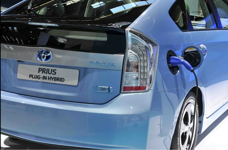
A plug-in hybrid electric vehicle (PHEV) is a hybrid electric vehicle whose battery can be recharged by plugging it into an external source of electric power, as well as by its onboard engine and generator. Similar to all-electric vehicles, plug-in hybrids displace emissions from the car tailpipe to the generators powering the electricity grid. These generators may be renewable or may have lower emissions than an internal combustion engine. Charging the battery from the grid can cost less than using the on-board engine, helping to reduce operating costs. A PHEV is shown below:
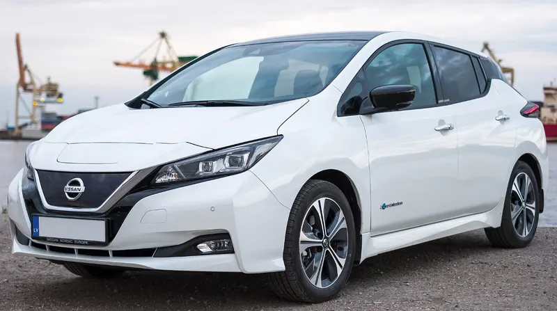
2) Battery electric vehicles (BEVs) - A battery electric vehicle (BEV), pure electric vehicle, only-electric vehicle, or all-electric vehicle is a type of electric vehicle (EV) that exclusively uses chemical energy stored in rechargeable battery packs, with no secondary source of propulsion (e.g. hydrogen fuel cell, internal combustion engine, etc.). BEVs use electric motors and motor controllers instead of internal combustion engines (ICEs) for propulsion. They derive all power from battery packs and thus have no internal combustion engine, fuel cell, or fuel tank. A Bev vehicle is shown below:
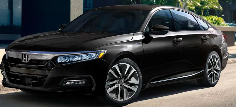
3) Battery assisted hybrid vehicles (BAHVs) - Mild hybrids (also known as power-assist hybrids, battery-assisted hybrid vehicles or BAHVs) are generally cars with an internal combustion engine equipped with an electric machine (one motor/generator in a parallel hybrid configuration) allowing the engine to be turned off whenever the car is coasting, braking, or stopped, yet restart quickly. Mild hybrids may employ regenerative braking and some level of power assist to the internal combustion engine (ICE), but mild hybrids do not have an electric-only mode of propulsion. A BAHV vehicle is shown below:
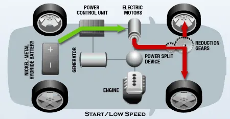
PROCEDURE - Here I have to design a pure electric car that is run by a motor and uses regenerative braking to charge the battery.
The layout of the pure electric vehicle is shown below:
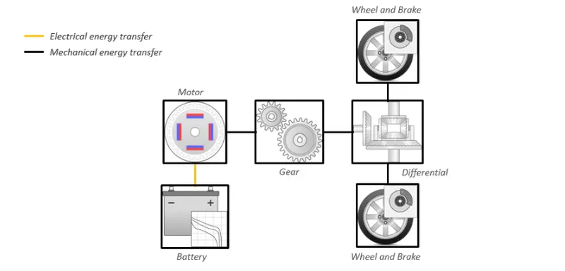
Electric vehicles take power from the batteries in the form of electrical energy and is supplied to electric motors via a controller thereby converting into mechanical work. When you push the accelerator pedal, the transducer connected to it sends the position to the processor. The position of the pedal is associated with the power given by the battery to the motor. The position value is calibrated accordingly & this information is sent to the controller. The batteries supplies only DC current so depending on the operation we have to do we can use power converters which will convert the signals as per our requirements then the converter will supply the power to the motor and that power supplied to the motor gets converted into mechanical energy which is transferred to the wheels for propulsion of the vehicle.
The components which are essential for electric vehicles are mentioned below:
1) Battery - batteries are the powerhouses of EVs, a substitute for fuel. Batteries used are made of dozens of small Lithium-ion(Li-ion) cells packed together in a box called a battery pack. Lithium-ion batteries are preferred instead of Lead-acid or Nickel-Cadmium (Ni-Cd) because of their numerous perks. Li-ion batteries have high energy density (can store more energy per kg). Smaller cells packed together to give another advantage of being able to dissipate the heat efficiently. Batteries will give power to the motor and will also store the charge.
2) Electric Motor - Electric motor is a device that will convert electric energy into mechanical energy. That mechanical energy is delivered to the wheels via a transmission system. Many EVs use a motor-generator that can perform regeneration well. The motors used in electric cars are both AC and DC motors.
3) Power converter - Power converter technology deals with processing and controlling the flow of electrical energy in order to supply voltages and currents in a form that optimally suited for the end user’s requirements. A power electronic converter uses power electronic components such as SCRs, TRIACs, IGBTs, etc. to control and convert the electric power. The main aim of the converter is to produce conditioning power with respect to a certain application.
Depending on the type of function performed, power electronic converters are categorized into the following types.
- AC to DC = Rectifier: It converts AC to unipolar (DC) current
- DC to AC = Inverter: It converts DC to AC of desired frequency and voltage
- DC to DC = Chopper: It converts constant to variable DC or variable DC to constant DC
4) Transmission system - Transmission system is the system by means of which power developed by the engine or motor is transmitted to road wheels to propel the vehicle. In automobiles, the power is developed by the engine or motor which is used to turn wheels. Therefore, the engine or motor is to be connected to the transmission systems for transmitting power to wheels. Transmission can also be automatic or manual. In a manual transmission, the clutch will be there to engage and disengage the driving shaft to the driven shaft. The function of the transmission system is to vary the torque
5) suspension system - The chassis of the vehicle is connected to the front and rear wheels through the medium of springs, shock absorbers and axles. All parts perform the function of protecting parts from shocks are known as suspension system. The automobile chassis is indirectly connected with axles by springs. It is done to prevent the vehicle body from road shocks due to bounce, pitch, roll or sway. These road shocks provide an uncomfortable ride and also adds stress to the automobile frame and body.
The suspension system has a spring and damper. The energy of road shock produced by the spring oscillates. These oscillations are arrested by the damper known as a shock absorber.
6) steering system - The car's steering system in the automobile, it is the process of running the vehicle in the desired direction by turning, usually the front wheels. For effective control of the vehicle throughout its speed range with safety, proper steering is necessary. The system allows a driver to use only light forces to steer a heavy car.
7) Tires and wheels - These are the components which maintain contact with ground and provide frictional contact with the road surface which allows the driving wheels to move the vehicle and they also allow braking to slow or stop the vehicle.
so i have created the model of an Electric vehicle from scratch in Simulink and the model is explained below:
First, let's see what Simulink is?
Simulink - Simulink is a MATLAB-based graphical programming environment for modeling, simulating, and analyzing multidomain dynamical systems. Its primary interface is a graphical block diagramming tool and a customizable set of block libraries. It offers tight integration with the rest of the MATLAB environment and can either drive MATLAB or be scripted from it. Simulink is widely used in automatic control and digital signal processing for multidomain simulation and model-based design.
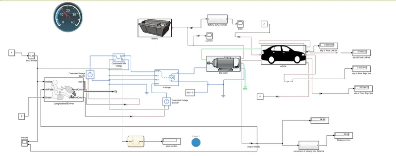
The Simulink model of my vehicle is shown below:
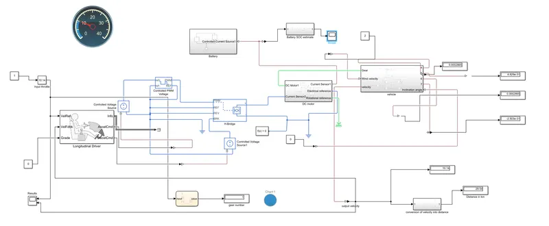
As it is mentioned above Simulink has so many blocks so I have created the model of EV using those blocks only.
The steps by which i created the model using different blocks is shown below :so at first i started with tire block.
1) Tire block - The Tire (Magic Formula) block models the tire as a rigid wheel-tire combination in contact with the road and subject to slip. When torque is applied to the wheel axle, the tire pushes on the ground (while subject to contact friction) and transfers the resulting reaction as a force back on the wheel. This action pushes the wheel forward or backward. If you include the optional tire compliance, the tire also flexibly deforms under load. The tire block is shown below:
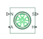
As you can see the block has 4 ports (N, S, A, H) in which A is the input port and s is the output port
N- Physical signal input port associated with the normal force acting on the tire. The normal force is positive if it acts downward on the tire, pressing it against the pavement.
A - Mechanical rotational port associated with the axle that the tire sits on.
H - Mechanical translational port associated with the wheel hub that transmits the thrust generated by the tire to the remainder of the vehicle.
S - Physical signal output port associated with the relative slip between the tire and road.
There are four tire block I have used here 2 for the front axle and two for the rear axle
The parameters of the tire that I used in my model are shown below:
For front axle tires :
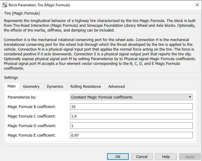
and for Rear axle tires :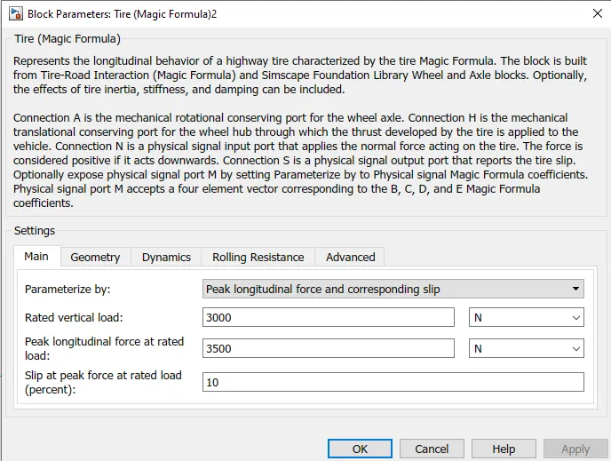
All these values are my assumed parameters, The rolling radius of all 4 wheels was 0.3 and here i have kept the rolling resistance coefficient of all four wheels 0.015
The next block I have used was the vehicle body block:
2) vehicle body - The Vehicle Body block represents a two-axle vehicle body in longitudinal motion. The vehicle can have the same or a different number of wheels on each axle. For example, two wheels on the front axle and one wheel on the rear axle. The vehicle wheels are assumed identical in size. The vehicle can also have a center of gravity (CG) that is at or below the plane of travel.
The block accounts for body mass, aerodynamic drag, road incline, and weight distribution between axles due to acceleration and road profile. Optionally include pitch and suspension dynamics. The vehicle does not move vertically relative to the ground. The block has an option to include an externally defined mass and an externally defined inertia. The mass, inertia, and center of gravity of the vehicle body can vary over the course of simulation in response to system changes. The vehicle block is shown below:

The block has 6 ports (NR,NF,H,V,W,beta)
NR - Physical signal output port for normal force on the rear axle. Wheel forces are considered positive if acting downwards.
NF - Physical signal output port for normal force on the front axle. Wheel forces are considered positive if acting downwards.
H - This port is used to connect the hub of the wheel
V - Physical signal output port for vehicle longitudinal velocity. This is my output velocity which I will observe in the plot.
W - Physical signal input port for headwind speed. Here i have given the wind speed as 2 m/s
beta - Physical signal input port for road incline angle. The inclination angle in my case is 0
The parameters of the vehicle body block are shown below:
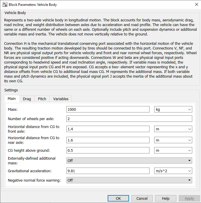
As you can see above the mass I have taken is 1000kg, and the drag parameters i have taken is as follows:
The drag force will resist the motion of the vehicle means it will act opposite to the direction of motion of the vehicle.
Frontal area = 0.6 `m^2`, Air density = 1.25 `frac(kg)(m^3)`, Drag coefficient = 0.2 and pitch variables and other variables are off.
Then I have made the connection of two blocks that are the vehicle body block and tire block the connections are shown below:
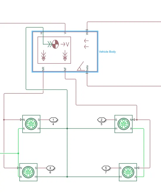
Here you can see that the hubs of front tires are connected to the hubs of rear tires and all the hubs are connected to the H port of the vehicle body block and the ports a of front and rear tires are connected to their adjacent front and rear tires to form the front and rear axle.
similarly, the N port of front tires and rear tires are connected to the N ports of adjacent front and rear tires which are further connected to the NF and NR ports of the vehicle body block.
The s port of the tire represents the slip that i have displayed in the output for each individual tire.
3)Gear block - Here I have used a simple gear block. The Simple Gear block represents a gearbox that constrains the connected driveline axes of the base gear, B, and the follower gear, F, to corotate with a fixed ratio that you specify. You choose whether the follower axis rotates in the same or opposite direction as the base axis. If they rotate in the same direction, the angular velocity of the follower, ωF, and the angular velocity of the base, ωB, have the same sign. If they rotate in opposite directions, ωF and ωB have opposite signs. The gear block is shown below:
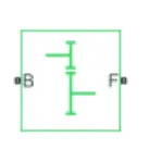
gear ratio (G) is defined as `frac{Nb)(Nf)` where Nb is the number of teeth in base gear and Nf is the number of teeth in follower gear.
This block has two ports B and F
B - Rotational mechanical conserving port associated with the base, or input, shaft.
F - Rotational mechanical conserving port associated with the follower, or output, shaft.
so I have connected the F port to the rear axle of the vehicle and B will be input to the gear which will come from the motor.
so I have made the subsystem combining the three blocks that is the tires, vehicle body, and gear block, and named it as 'vehicle'.
the whole subsystem looks like this:
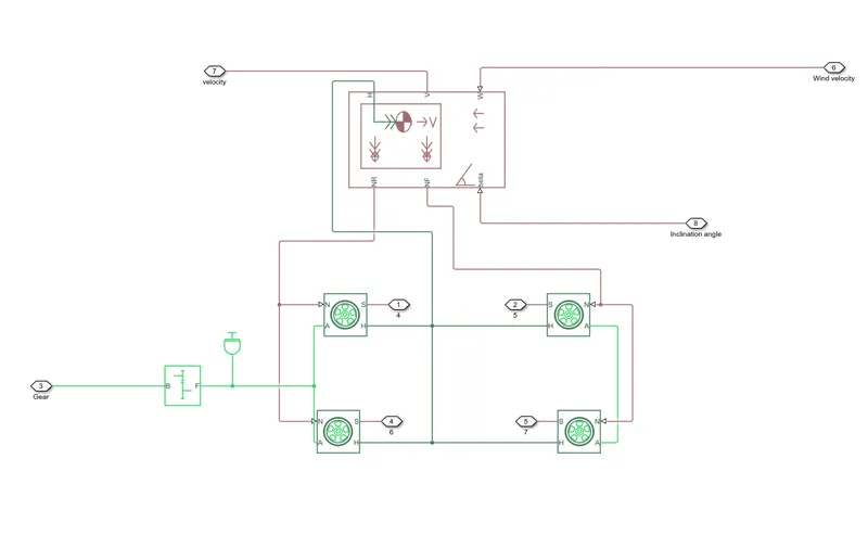
4) DC motor - A DC motor is a motor that requires DC signal input for its working but here I have used a permanent magnet DC motor.
The working principle of DC motor is when a current-carrying conductor is placed in a magnetic field, it experiences a force. A permanent magnet DC motor also works on the same principle. In a PMDC motor, permanent magnets (located in stator) provide magnetic field, instead of the stator winding. The stator is usually made from steel in cylindrical form. Permanent magnets are usually made from rare earth materials or neodymium.
The rotor is a slotted armature which carries armature winding. Rotor is made from layers of laminated silicon steel to reduce eddy current losses. Ends of armature winding are connected to commutator segments on which the brushes rest. Commutator is made from copper and brushes are usually made from carbon or graphite. DC supply is applied across these brushes. The commutator is in the segmented form to achieve unidirectional torque. The reversal of direction can be easily achieved by reversing the polarity of the applied voltage.
The DC motor block is shown below:
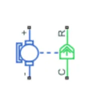
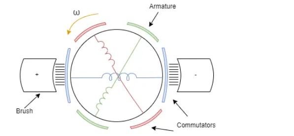
There are 4 ports in the motor block above
+ve terminal - Electrical conserving port associated with the DC motor positive terminal.
-ve terminal - Electrical conserving port associated with the DC motor negative terminal.
c - Mechanical rotational conserving port associated with the DC motor case.
R - Mechanical rotational conserving port associated with the DC motor rotor.
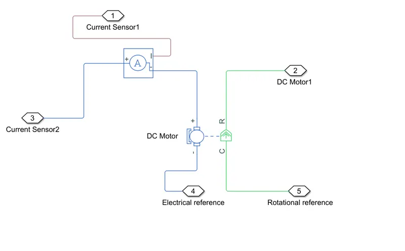
The R port of the motor I have connected to the B port of the gear block meaning the R port will provide input to the gear. and port C is connected to the mechanical rotational reference.
The -ve terminal port is connected to the electrical reference and the +ve terminal port is connected to the current sensor block
The motor parameters I have used are shown below:
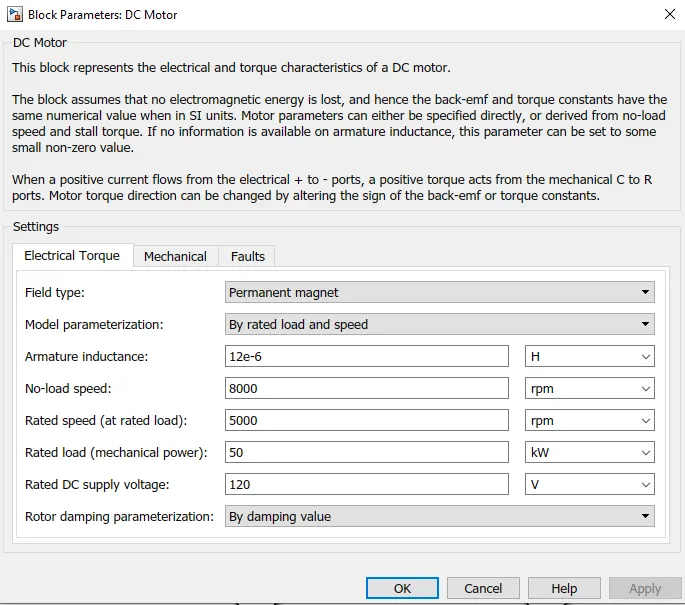
Here you can see that the motor's no-load speed I have assumed is 8000 rpm and rated speed at rated load is 5000 rpm and the rated DC supply I have given is 120V. and the rest values of mechanical and faults parameters I have kept as default only.
5) current sensor block - The Current Sensor block represents an ideal current sensor, that is, a device that converts current measured in any electrical branch into a physical signal proportional to the current. Connections + and – are electrical conserving ports through which the sensor is inserted into the circuit. Connection I is a physical signal port that outputs the measurement result. The current sensor block is shown below:
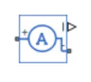
It has two ports +ve and -ve the -ve will be connected to the motor and the +ve will be connected to the H bridge block.
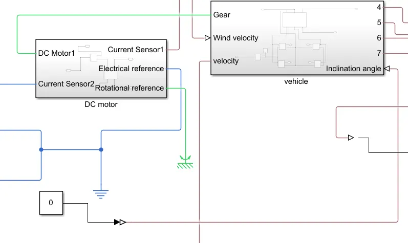
Here again, I have made a subsystem representing the motor block and current sensor and I have named as 'DC motor'. The subsystem is shown
6) H-bridge block - An H-bridge is a simple circuit that lets you control a DC motor to go backward or forward. You normally use it with a microcontroller, such as an Arduino, to control motors. An H-bridge is an electronic circuit that switches the polarity of a voltage applied to a load.
The term H-bridge is derived from the typical graphical representation of such a circuit. Suppose An H-bridge is built with four switches (solid-state or mechanical). When the switches S1 and S4 are closed (and S2 and S3 are open) a positive voltage is applied across the motor. By opening S1 and S4 switches and closing S2 and S3 switches, this voltage is reversed, allowing reverse operation of the motor.
Using the nomenclature above, the switches S1 and S2 should never be closed at the same time, as this would cause a short circuit on the input voltage source. The same applies to the switches S3 and S4. This condition is known as shoot-through.
The H bridge block is shown below:
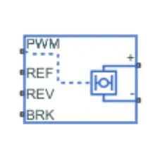
as you can see it has six ports:
+ve terminal - Electrical conserving port associated with the positive load connection.
-ve terminal - Electrical conserving port associated with the negative load connection.
PWM - Electrical conserving port associated with the pulse-width modulated signal. The voltage is defined relative to the REF port.
REF - Electrical conserving port associated with the floating zero volt reference.
REV - Electrical conserving port associated with the voltage that controls when to reverse the polarity of the H-Bridge block output.
BRK - Electrical conserving port associated with the voltage that controls when to short circuit the H-Bridge block output.
The +ve terminal port i have connected to the positive terminal of the current sensor block that is already explained above.
The -ve terminal is connected to electrical reference, the H bridge PWM port will get its input from the controlled PWM voltage block which I will describe in the next section.
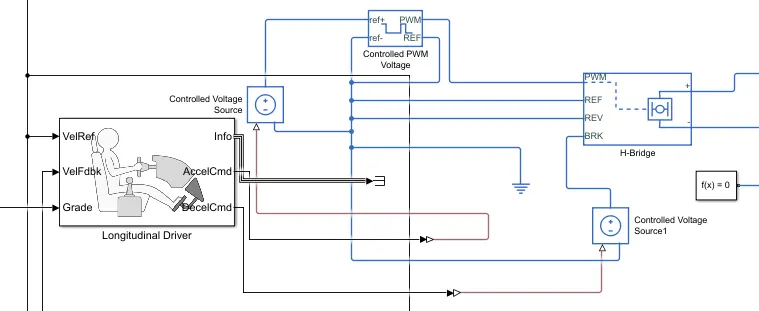
Here I am not running my vehicle in reverse direction so i will connect that port to the ground, the reference port is also connected to controlled PWM voltage which will be further connected to the ground. The BRK port will be connected to a controlled voltage source which will be again connected to a ground-controlled voltage source that will provide the controlled input as per driver requirement.
The connection i have made on this is shown below:
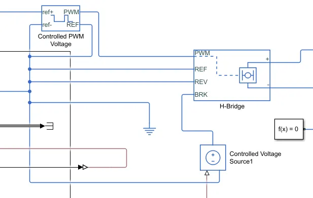
The parameter that i have used for H bridge is shown below:
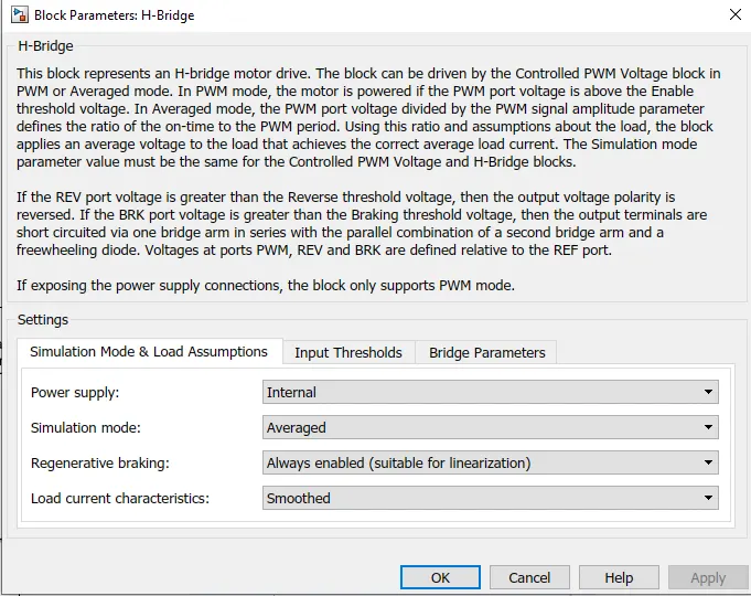
here you can see that the power supply I have given is internal and the simulation model is averaged, the regenerative braking is also enabled.
The input thresholds i have kept as default only and in bridge parameter, the output voltage amplitude i have given is 320V and freewheeling diode resistance i have kept as default only that is 0.05 ohm.
the input threshold are shown below:
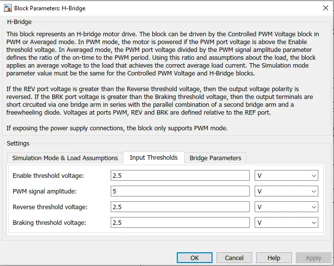
Here in the simulation mode there are two modes PWM and averaged:
PWM - the H-Bridge block output is a controlled voltage that depends on the input signal at the PWM port. If the input signal has a value greater than the Enable threshold voltage parameter value, the H-Bridge block output is on and has a value equal to the value of the Output voltage amplitude parameter.
Averaged - This mode has two Load current characteristics options:
-
smoothed - The
Smoothedoption assumes that the current is practically continuous due to load inductance. -
unsmoothed - The unsmoothed option assumes that the current is discontinuous.
i have set it to average because i want to simulate the results faster.
Braking mode is invoked when the voltage presented at the BRK port is larger than the Braking threshold voltage.
7) Controlled PWM voltage block - This block will give input to the H bridge block. The Controlled PWM Voltage block represents a pulse-width modulated (PWM) voltage source.
-
Electrical input ports — The block calculates the duty cycle based on the reference voltage across its ref+ and ref- ports. This modeling variant is the default.
-
PS input — Specify the duty cycle value directly by using an input physical signal port.
This block will provide pulses and from these pulses, the variable output voltage will be produced and motor speed and torque are going to change.
The block looks like this:
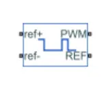
Here you can see that 4 ports are there:
ref+ = positive electrical reference port which will be connected to a controlled voltage source.
ref - = Negative electrical reference.
PWM - Electrical conserving port associated with the pulse-width modulated signal.
REF - This is an Electrical conserving port associated with the floating zero volt reference.
the connection of these ports is: the PWM port is connected to the PWM port of the H bridge so this will act as an input to the motor, the REF port is connected to the Reference part of the H bridge. The ref- will be connected to the ground, Now the input to the control system is given by a controlled voltage source so the ref+ will be connected to the controlled voltage source.
The parameters of the controlled PWM voltage block is shown below:
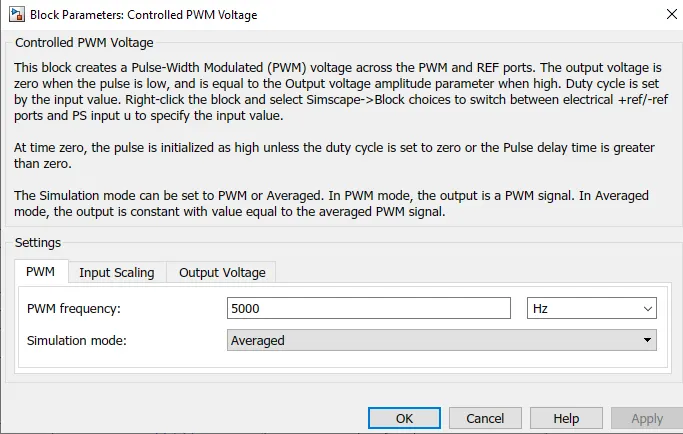
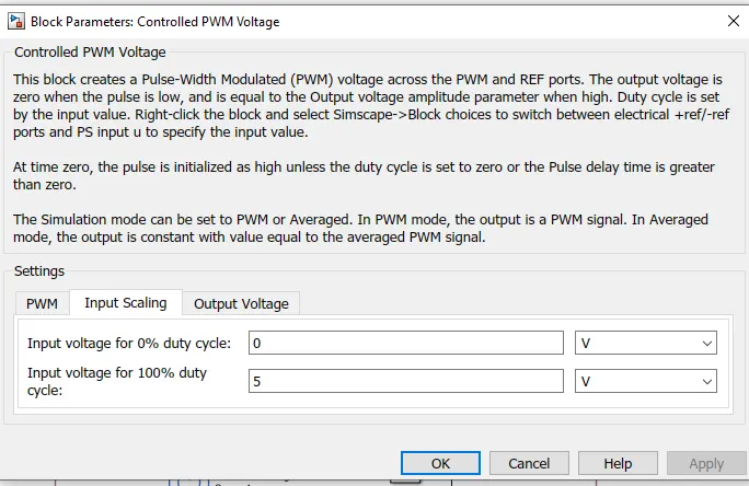
Duty cycle - Duty cycle is a parameter that is measured in percentage which shows the amount of time the switch is on.
Duty cycle = `frac{(Time)on}{Total time}`
Total time = (Time)on + (Time)off
The duty cycle basically controls the output voltage.
Here the input voltage for 100 % duty cycle I have kept is 5V and the output voltage amplitude is also 5V
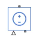
8) Controlled voltage source - The Controlled Voltage Source block represents an ideal voltage source that is powerful enough to maintain the specified voltage at its output regardless of the current flowing through the source.
The output voltage is V = Vs, where Vs is the numerical value presented at the physical signal port.
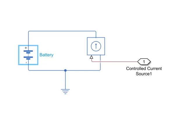
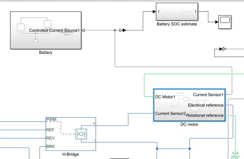
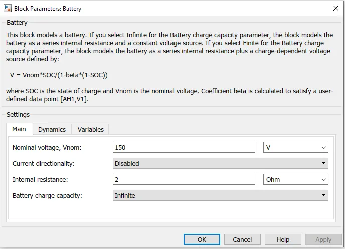
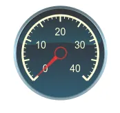
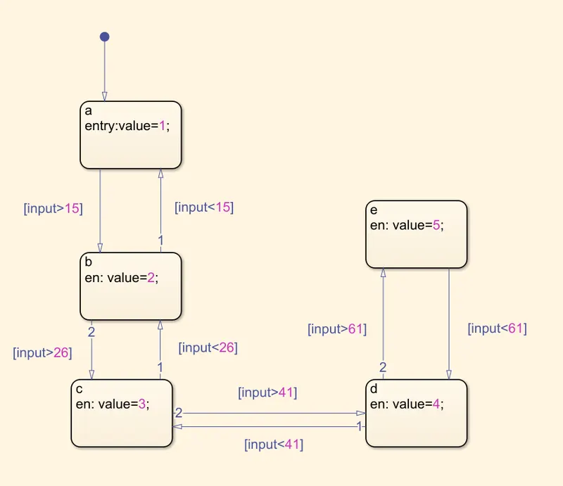

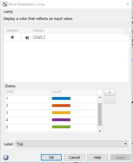
| GEAR NUMBER | COLOUR |
| 1 | BLUE |
| 2 | ORANGE |
| 3 | YELLOW |
| 4 | PURPLE |
| 5 | GREEN |