Week-7 Challenge: DC Motor Control
AIM - To perform the tasks that are given to me.
OBJECTIVES - 1) To run the MATLAB demo ‘Speed control of a DC motor using BJT H-bridge’. and have to modify the model such that the armature current doesn’t shoot up when motor changes direction from forward to reverse.
2) To refer the ‘The Four-Quadrant Chopper DC Drive (DC7) block’ and to compare it with H - bridge model.
3) To make suitable model using DC7 block and to make result report.
4) To explain about the operation of BLDC motor.
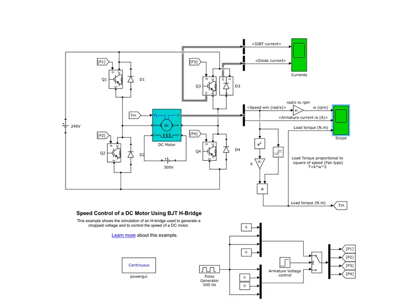
PROCEDURE -For the first part - For this part i have to run the model of ‘Speed control of a DC motor using BJT H-bridge’.
The Bipolar Junction Transistor (BJT) when used for power switching applications, operates as an IGBT. When it is conducting (BJT operating in the saturated region), a forward voltage Vf is developed between collector and emitter (in the range of 1 V). Therefore, the IGBT block can be used to model the BJT device.
The H-bridge consists of four BJT/Diode pairs (BJT simulated by IGBT models). Two transistors are switched simultaneously: Q1 and Q4 or Q2 and Q3. When Q1 and Q4 are fired, a positive voltage is applied to the motor and diodes D2-D3 operate as free-wheeling diodes when Q1 and Q4 are switched off. When Q2 and Q3 are fired, a negative voltage is applied to the motor and diodes D1-D4 operate as free-wheeling diodes when Q2 and Q3 are switched off.
The simulink model is shown below:
Here the input is given in the form of pulse generator whose parameters are shown below:
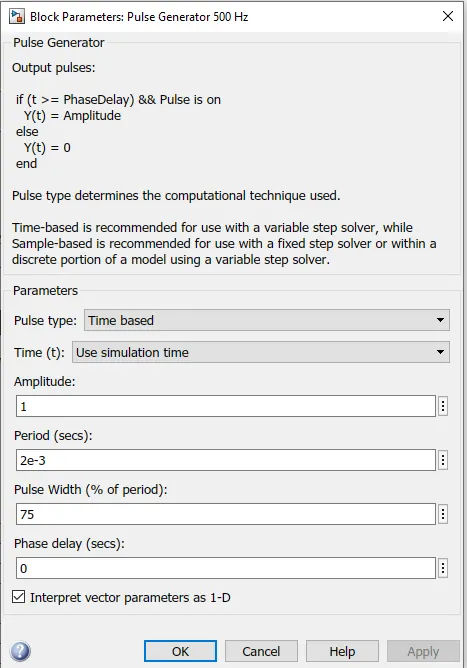
Here you can see that the pulse width is 75% and it represents the duty cycle meaning that the motor will run on 75% duty cycle.
The time step that is used is 0.5s. The model is made to run for 1s, The output that i got after simulating the model is shown below:
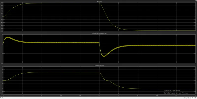
Here u can see there are 3 graphs which are plotted
first one is a plot of speed (rpm) vs time(s), which will show the speed of motor
second one is a plot of Armature current (Amp) vs time(s), which will show the armature current
third one is a plot of load torque (Nm) vs time(S),which will show the value of load torque.
In the above graph you can see that at t = 0.5s the motor started working inr reverse direction and that is why there is a shoot up in armature current value so i have to modify the model to make sure that there is no shoot up in armature current value.
So, for that purpose i will reduce the duty cycle, duty cycle is a parameter that is measured in percentage which shows the amount of time the switch is on.
Duty cycle = `frac{(Time)on}{Total time}`
so i will make some changes in the input, that is the pulse generator parameter. The changes in parameter is hown below:
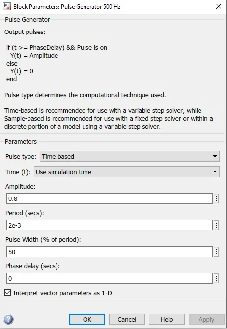
Here you can see that i have reduced the amplitude to 0.8, and pulse width to 50% which implies that the duty cycle is 50% which was 75% in earlier case. Now the motor will run for 50% duty cycle apart from changing the input parameter i will not change any other parameters they will be same as it was in earlier case.After that i will just run the model for 1s and see observe the outputs
The plot for 50% duty cycle is shown below:
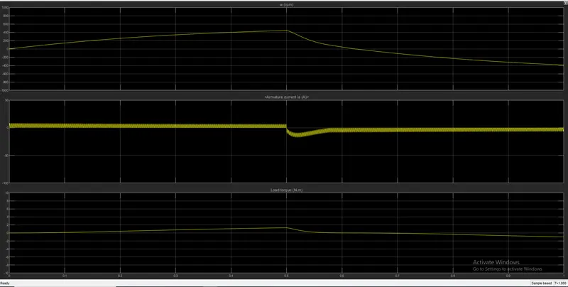
Here you can see that in the second plot the armature current which was shooting up in earlier case is now stable.
so i found out that by reducing the duty cycle i was able to satbalize the armature current so if want to stabalize more i will reduce the duty cycle again.
For the second part - The four quadrant chopper dc drive - The bock is shown below:
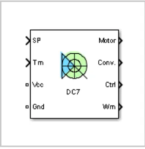
The Four-Quadrant Chopper DC Drive (DC7) block represents a four-quadrant, DC-supplied, chopper (or DC-DC PWM converter) drivefor DC motors. This drive features closed-loop speed control with four-quadrant operation. The speed control loop outputs the reference armature current of the machine. Using a PI current controller, the chopper duty cycle corresponding to the commanded armature current is derived. This duty cycle is then compared with a sawtooth carrier signal to obtain the required PWM signals for the chopper.
The four quadrants are shown below of a dc drive:
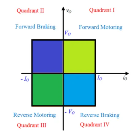
Here you can see that the 1st quadrant is for Forward motoring and in that quadrant the power will be positive.
The 2nd quadrant belongs to Forward braking and in that the power will be negative.
The 3rd one belongs to Reverse motoring and in that the power will be again positive.
The final 4th quadrant belongs to Reverse braking and in that again the power will be negative.
The chopper circuiit used in model looks like this:
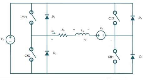
here the ch1,ch2,ch3,ch4 refers to 4 choppers of four quadrants
Now if i want to operate the first quadrant i will have to operate the ch1 and ch4 simultaneouisly the load gets directly connected to source and hence the output voltage becomes equal to source voltage. When ch1 is switched off the load current freewheels through ch4 so we get positive values of output voltage and current.
For oprating the second quadrant ch2 is opererated for some time and it is then off as a result the value of load voltage is postive and the value of load current is negative.
For operating the third quadrant ch3 is operated,ch1 is kept off and ch2 is also on for some time and when ch3 is off the load current freewheels tohrough the ch2 as a result we get the values of load current and load voltage as neagtive.
For operating the fourth quadrant ch4 is operated and rest all are kept off,and when ch4 is off and as a result of that we get the value of load current as positive and the value of load voltage as negative.
Comparisons with H bridge - In four quadrant chopper system the regenerative braking is possible but in case of H bridge it is not possible.
The values that we get as output in four quadrant system is chopped and it is not continous but in case of H bridge the values are continous.
The switching frequency of four quadrant chopper dc drive is higher than that of H bridge.
In four quadrant chopper system the PI controller is used but in H bridge the PI controller is not used.
For the third part - For this purpose i have to make a suitable EV model using D7 block. The simulink model of the electric vehicle is shown below:
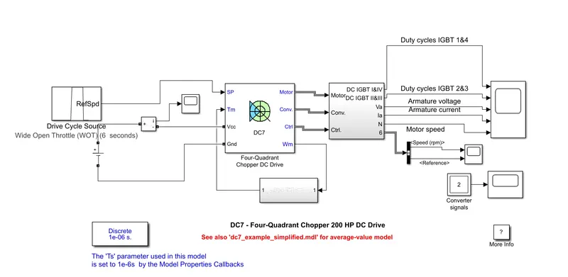
Here you can see that the four quadrant chopper dc drive is connected to a current measurement block which is getting its input from a DC voltage source of 100V. For the speed reference input i have given a wide open throttle drive cycle whose parameters are shown below:
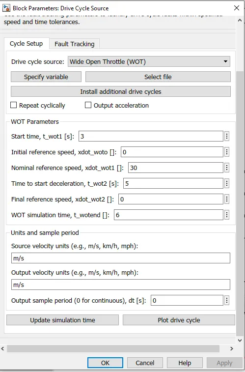
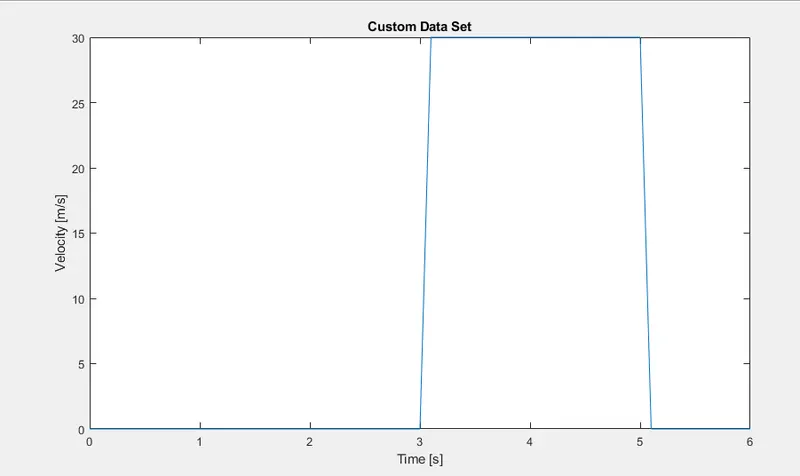
Here you can see that the start time is 3s meaning the vehicle will be at rest for starting 2s and on 3s it will start accelerating. The reference speed given here is 30 m/s. and time to start deceleration is given as 5s meaning after 5s the vehicle will start decelerating and it will come ta final reference speed which is o means it will be come to rest.
The plot for this drive cycle is shown below:
The four quadrant chopper dc drive is aslo connected with torque characteristics of the vehicle.
The torque charateristics equation is given by T = `24.7 + 0.0051w^2`
i have created a subsystem for implementing that equation
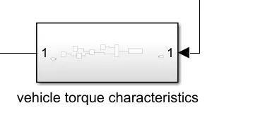
the inside of this subsystem looks like this:
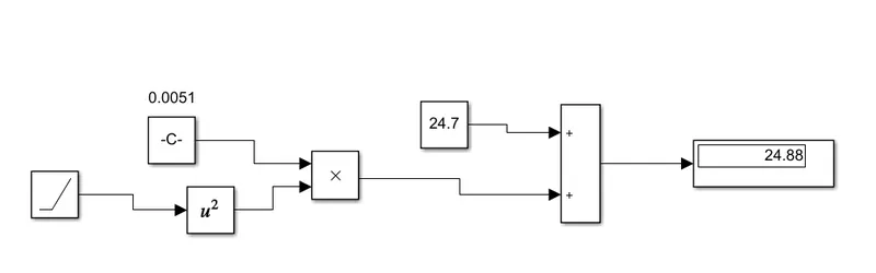
Here for giving the values of speed i have used the ramp block. The parameter of ramp block is shown below:
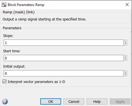
The sampling time i have used here is very less so that i can accurate results. I will run the model for 6s and will observe the output
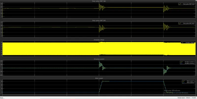
The ouput is shown below:
For the fourth part - BLDC motor is a brushless type of DC motor. A BLDC is a permanent magnet electric motor which is driven by direct current (DC) electricity and it accomplishes electronically controlled commutation system (commutation is the process of producing rotational torque in the motor by changing phase currents through it at appropriate times) instead of a mechanically commutation system. Unlike conventional brushed type DC motor, wherein the brushes make the mechanical contact with commutator on the rotor so as to form an electric path between a DC electric source and rotor armature windings, BLDC motor employs electrical commutation with permanent magnet rotor and a stator with a sequence of coils. In this motor, permanent magnet (or field poles) rotates and current carrying conductors are fixed.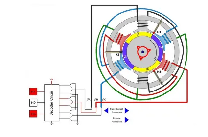
Construction of BLDC motor - It consists of a frame in which the rotor and stator are fixed. The rotor is the rotating part and the stator is the stationary part. The frame is used to hold the inner peripherals and also used to protect them from the environment. The rotor is fixed with some permanent magnets and stator has some coils that act as an electromagnet. The number of poles depends upon the operational requirement. The stator has some slots in which the coils are placed. The number of coils to be placed depends upon the number of poles. Depending upon the requirement these coils are energized.
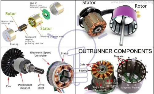
Working - BLDC motor works on the principle similar to that of a conventional DC motor, i.e., the Lorentz force law which states that whenever a current carrying conductor placed in a magnetic field it experiences a force. As a consequence of reaction force, the magnet will experience an equal and opposite force. In case BLDC motor, the current carrying conductor is stationary while the permanent magnet moves.
When the stator coils are electrically switched by a supply source, it becomes electromagnet and starts producing the uniform field in the air gap. Though the source of supply is DC, switching makes to generate an AC voltage waveform with trapezoidal shape. Due to the force of interaction between electromagnet stator and permanent magnet rotor, the rotor continues to rotate. With the switching of windings as High and Low signals, corresponding winding energized as North and South poles. The permanent magnet rotor with North and South poles align with stator poles causing motor to rotate.
The switching action of the motor is shown below:
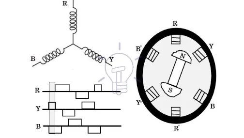
The motor produces torque brcause of development of attractive forces (N-S or S-N alignment) and repulsive forces (N-N or S-S alignment)
Advantages of BLDC motor - 1) High effieciency due to permanent magnet rotor.
2) less maintenance and insoection required.
3) less electromagnetic interference
BLDC motors are widely used in hybrid and electric vehicles.
RESULT - 1) I have modified the model to make sure that the armature current does not shoot up. I have done that by reducing the pulse width to 50% which refers to duty cycle. The plot for the modified is shown below:
3) The plot for EV model using DC7 block is hown below:
Here you can see that the armature voltage is almost constant throughout the time period.
The armature current is iniially zero when the vehicle is at rest and when the vehicle starts accelerating you can see the spike after 3 s then again it is zero and when the vehicle is decelerating the value of armature current drops below zero and then again comes to zero.
The last plot is for the motor speed, the max speed reached here is 30 and that speed is constant as per out drive cycle input then again the motor is coming to rest after 5 seconds.
CONCLUSION - All the tasks that are given to me has been completed successfully and the results are plotted and described in the result section.