Week 9 - Project 1 - Door Applique Design with Engineering Features
AIM - To design the Door applique with Engineering features.
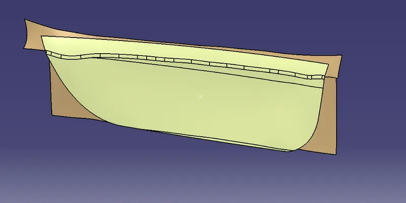
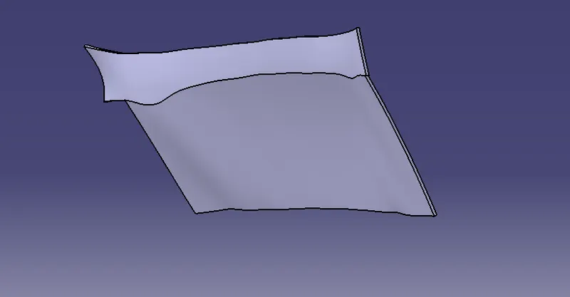
PROCEDURE - The class A surface given to me is shown below:
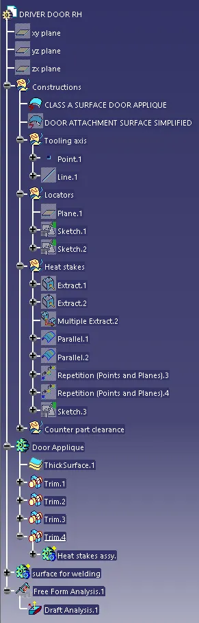
The Tree structure of the component is shown below:
I will start by creating the tooling axis for the component
Tooling axis - The tooling axis is defined as the direction in which the mold opens or core and cavity opens and closes. The selection of the correct tooling axis is important to ensure the component is taken out perfectly and also the cost of the component should be less.
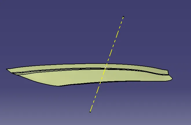
I will start by inserting a geometrical set and naming it as a tooling direction. For creating the tooling axis i will analyze the model and see from which direction I can see the whole model. so here the direction i have chosen for the tooling axis is along y-direction because along y-direction the whole model is visible properly.
so i will create a point in the middle of the door attachment surface and then I will create one line from that point along the y-direction and that line will be my tooling axis. Because in that y-direction the component will be easily ejected from the mold. The tool should clear in z and x-direction and I have
The tooling axis is shown below:

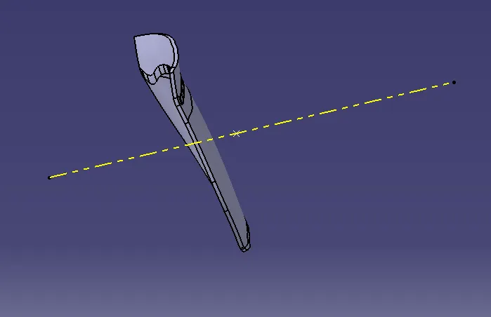
After creating the tooling axis I will just thicken the door applique surface to 2.5 mm cause that will be my thickness. By thickening the surface it will convert the surface body into a solid body. The thicken body is shown below:
After thickening the body I wi create the locators.
Locators - locating pins are used in work holding fixtures and jigs to secure workpieces during the production of parts. There are two classifications of locating pins, 2-way and 4-way. A simple method to remember the difference between them is to consider the 3 axes of translational motion, and the 6 corresponding directions or Degrees of Freedom. A 2-way locating pin restricts motion along 1 axis (or 2 degrees of Freedom), like a round pin in a slot. Likewise, a 4-way pin restricts 4 degrees of freedom along 2 axes. A round locating pin located concentrically in a hole is a common application of a 4-way pin and helps to further secure the piece. In order to sufficiently locate a part, a minimum of one of each type of pin is required to prevent excess motion of the workpiece, and more locating components may be used as needed.
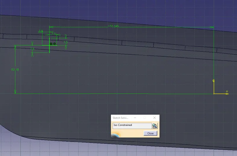
so here I will design both a 4-way locator and a 2-way locator. First i will create 2 four-way locators. so for that on the point that i have created on the door attachment surface, I will create one plane and in that plane, i will create a sketch. The sketch is shown below:
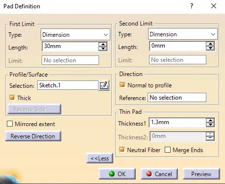
Then i have padded the sketch. The pad parameters are shown below:
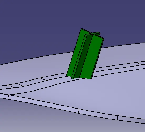
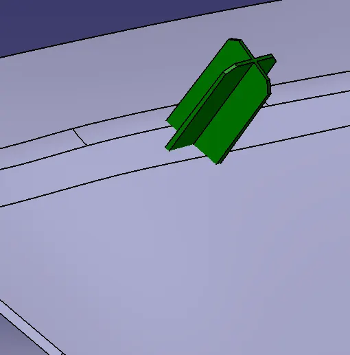
Then i have provided the draft according to the design rules for ribs that is 0.5 degrees of draft and provided tha chamfer is well. The draft and chamfer is shown below:
Then i have provided the fillets to all the edges. The fillet parameters are shown below:
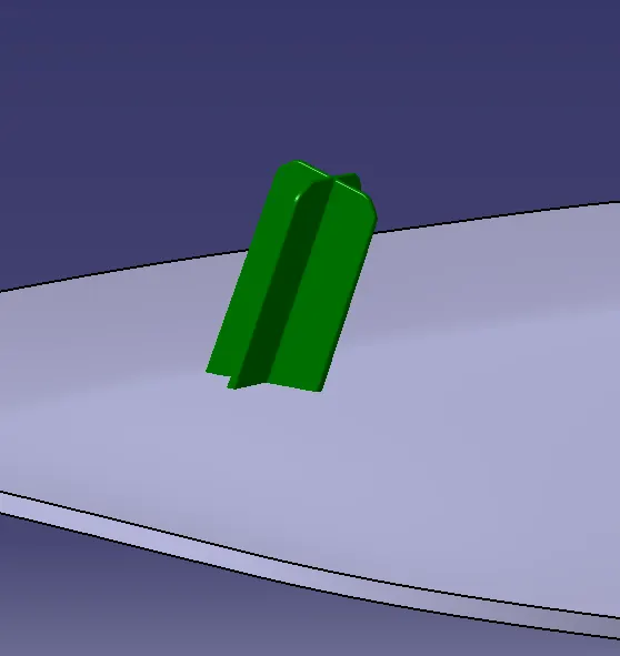
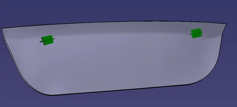
then at last i have trimmed the 4-way locator from the door applique body. And i have created the same 4-way locator on the other side as well. I have done by translating the solid body of 4-way locator to a certain distance. The other 4-way locator is shown below: Every parameter of this locator is similar to the first one.
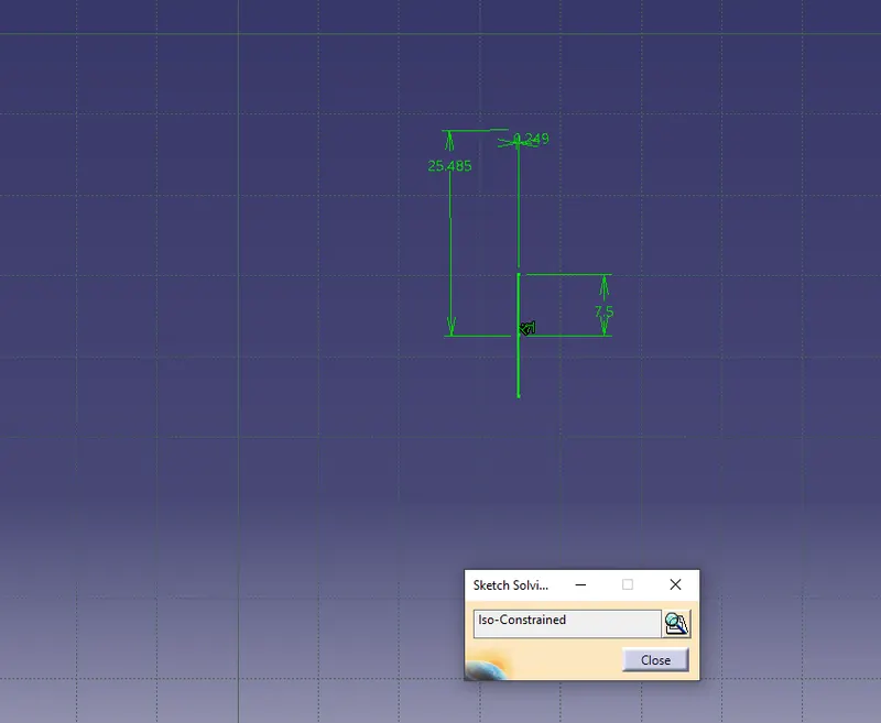
After doing this I have created the 2-way locator at the bottom portion of the surface. so for that also I have created one sketch. The sketch is shown below:
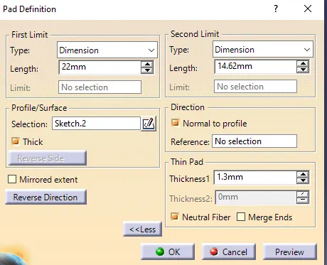
And again I have used the pad command to create a solid body. The pad is shown below:
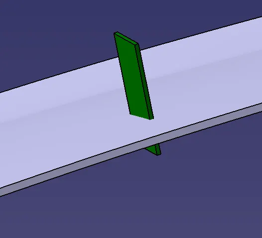
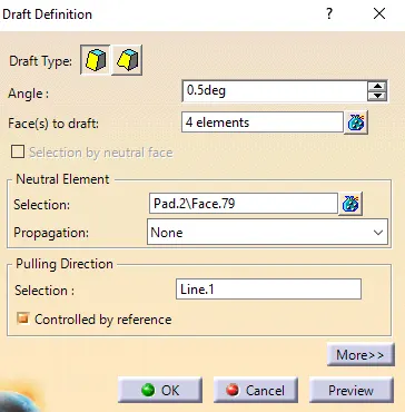
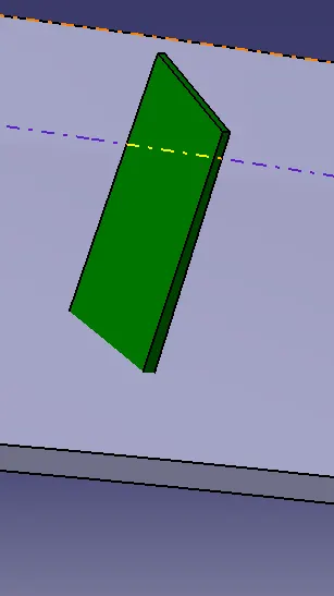
Then again I have provided the draft according to the design rules. The draft is shown below:
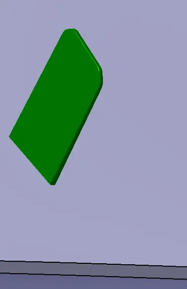
Then I have provided the chamfer and the fillets according to the design rules. The fillets and chamfer are shown below:
Then again I have trimmed this body from the door applique body. After doing i have also thickened the door attachment surface. The thickened body is shown below:
After this, I will design the heat stakes.
Heat staking - Heat staking also known as thermoplastic staking is the process of joining two dissimilar materials together. In heat staking, we use local heating and cooling to raise the temperature of plastic components and allow plastic reforming to be carried out. This reforming can be used in a wide variety of applications.
Applications range from staking plastic bosses for assembly of car door panels to joining PCBs to plastic housings. Benefits of this technique include; no vibration damage, no particulates, the ability to stake metalized coated applications, and the capability to stake in difficult to access or restricted areas.
The progressive melting of plastic under continuous pressure forms the head. When staking the right combination of heat and pressure for the application is critical.
The advantages of Heat staking are as follows:
1) simplification of the machinery
2) Reduced cost of machinery
3)Multiple fastening points
4) Allows higher density of welds compared to hot air cold form or ultrasonic welding.
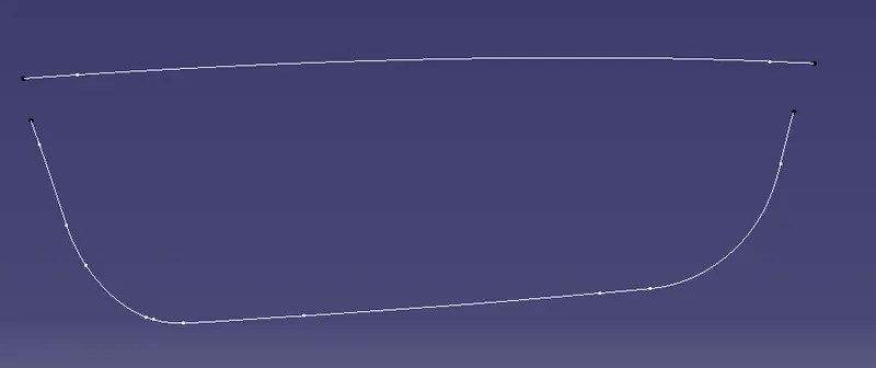
For creating the heat stakes i have first extracted the boundaries of the door applique. The extracted boundaries is shown below:
Then i have used the parallel curve feature to make a parallel extract of the above-extracted boundaries. The parallel curve is shown below:
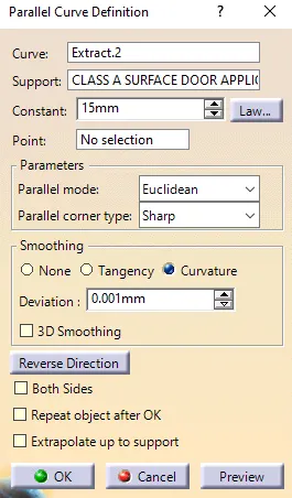
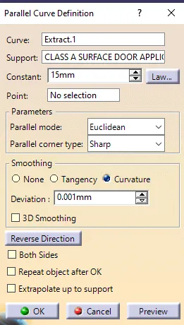
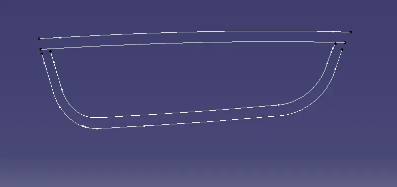
Then i have created multiple points on both the parallel curves. I have done this because on these points only I will create the heat stakes.
The multiple points are shown below:
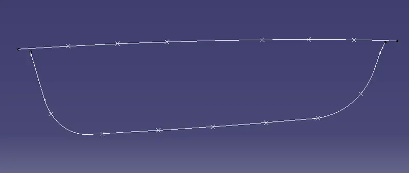
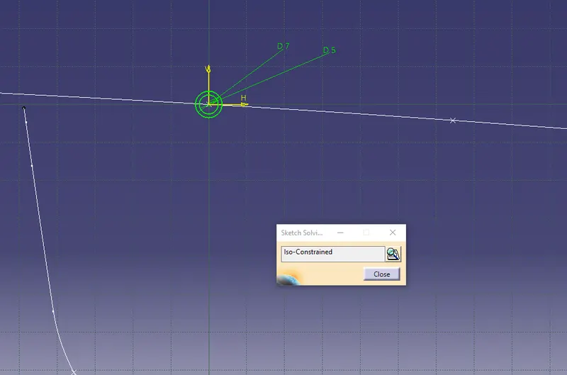
Then i have created one sketch on the first point. The sketch of heat stake is shown below:
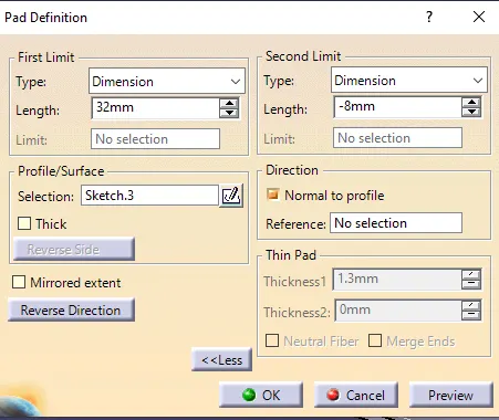
Then I have padded the sketch. The pad is shown below:
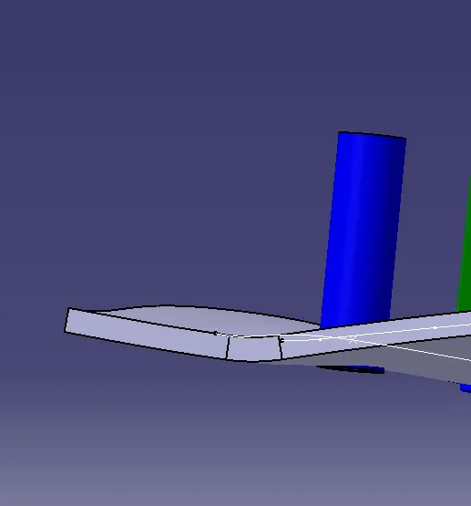
I have provided the draft and fillets to this heat stake after padding it. Then I have translated the heat stake at every point I created on the parallel curve. After translating it to all the points I have trimmed it with the door applique body.
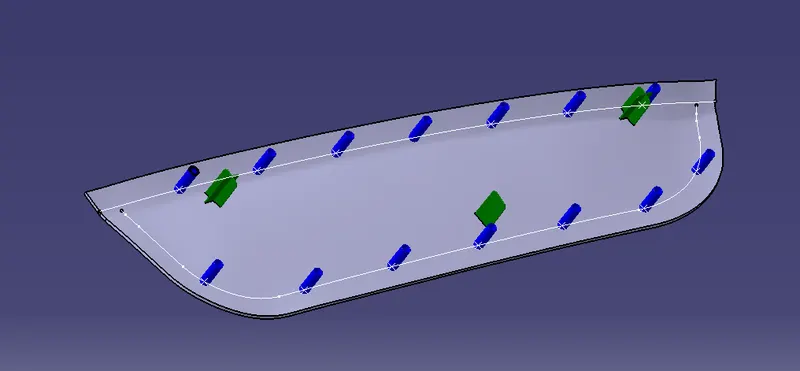
Now for the counterpart clearance, I have made the cutouts. For that, i have created few sketches on the plane that i have created earlier.
The counterpart clearance for the locator the sketch I have created is shown below:
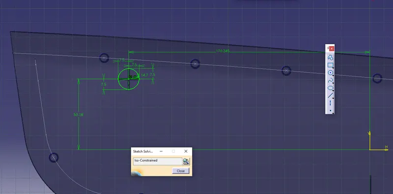
here I have to make sure that the clearance between the locators and this cutout is 0.1mm so according to that I have made the sketch. After this again I have made it a solid body by padding it and I have removed it from the door attachment surface to get that cutout. The cutout is shown below:
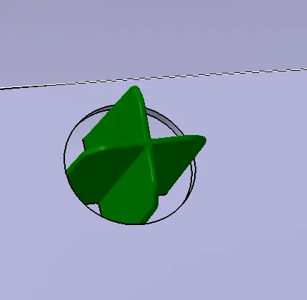
similar thing I have done for the other locators considering the clearance I have created the sketch and made a solid body and then removed it.
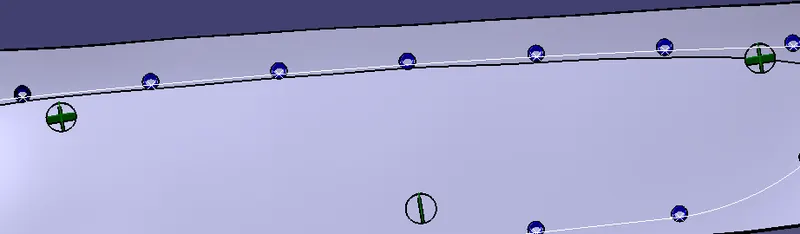
Then I have made the counterpart clearance for the heat stakes again following the same procedures. So for heat stakes, the cutout is shown below:
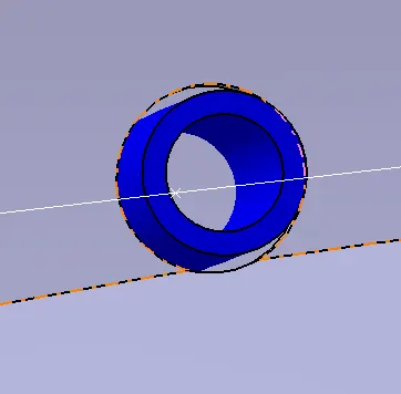
Then I have used the user-defined pattern to pattern it to all the points. The pattern is shown below:
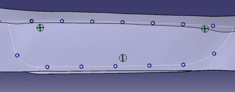
Now my part is complete and next i have done the draft analysis on the component.
Draft analysis - Draft analysis is a technique to analyze whether the component created is manufacturable or not based on the draft conditions applied. So here i will provide the direction in which the component should be ejected to get the easy removal. My direction will be the tooling axis that I have created.
The minimum draft value for the Automotive plastic component is 3 degrees and those for the texture faces 7 degrees od draft is suitable. The draft is provided to the component for easy removal from the mold in case of the plastic component. And For the attachment features the draft allowed 0.5 degrees.
So here I will change the customize view parameters and will select the material mode.
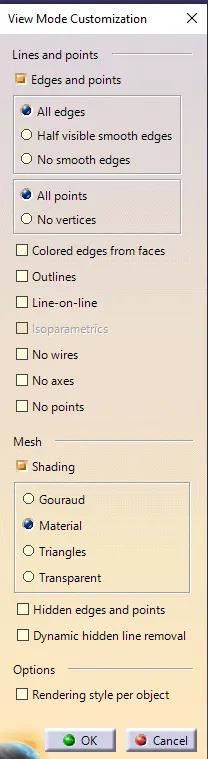
Then I will go insert and select the analysis and in the analysis, I will select the draft analysis. The draft analysis block is shown below:
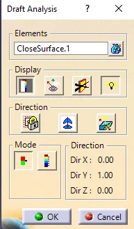
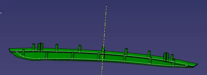
In the above fig. under the display, section selects the color scale and turn on the light effect for proper visualization. then under the direction section, I will click on the compass and will drag the compass from vehicle zero to my tooling axis. and then I will click on the lock feature and will select the class on the surface. The result is shown below:
The color scale is shown below:
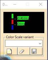
In the above fig. The Green color shows that the draft provided is more than 0.48 degrees
The Red color shows that the draft provided is between 0 and 0.48 degrees
The Blue color shows that the draft provided is negative
RESULT - Here I have designed the door applique along with heat stakes and locators and I have done the draft analysis on the door applique also. The result of the draft analysis is shown below:
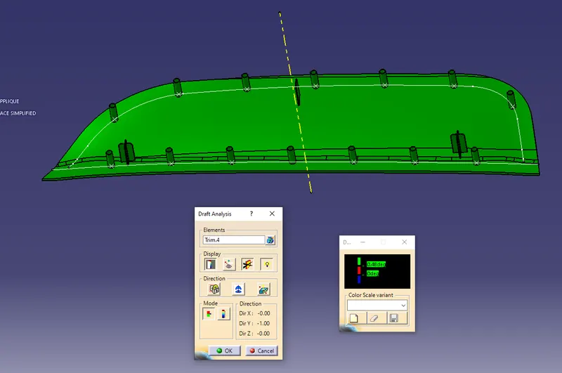
In the above fig, u can see that I have provided a draft of the component according to the design rules and now I can say that my component is manufacturable.
CONCLUSION - This concludes the design of the Door Applique with Engineering Features.