Door Arm Rest Week 8 Challenge
AIM - To create the solid door armrest and to perform the draft analysis on it.
PROCEDURE - Here Class A Surface which is given to me is shown below:
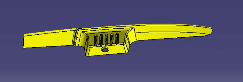
Now from the above shown fig. i have to create the solid component creating the CLASS B and CLASS C surface. so first i will create the tooling axis.
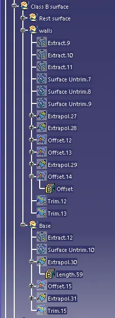
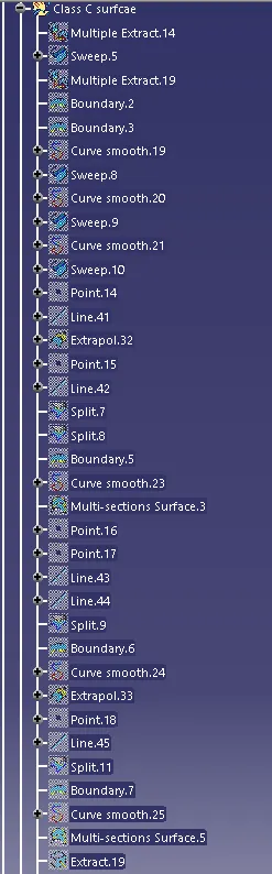
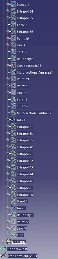
The tree structure of the model is shown below:
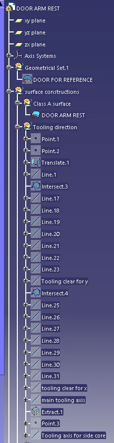
Tooling axis - The tooling axis is defined as the direction in which the mold opens or core and cavity opens and closes. The selection of the correct tooling axis is important to ensure the component is taken out perfectly and also the cost of the component should be less.
I will start by insering a geometrical set and naming it as a tooling direction. For creating the tooling axis i will analyze the model and see from which direction i can see the whole model. So on analyzing the model i found out that z-axis will be perfect for creating the tooling axis. Because along the Z direction, only the whole component is visible.
For the creation of the tooling axis, i have first created the point on the center of the hole which is there on the class A surface. Then I will create a dummy line just for my reference only along the Z direction. The dummy line is shown below:
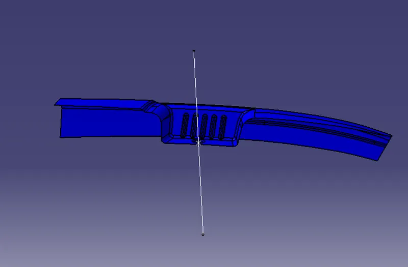
Then since I have chosen the Z direction as my tooling axis. Then I have to make sure that the tool clear in both the direction that is X and Y direction. Before creating the line I have also inserted an axis system on the point.
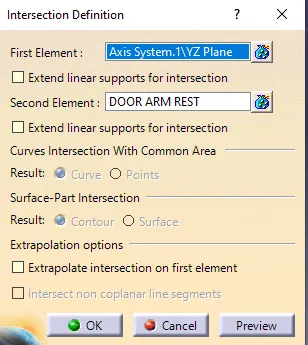
First, i would get the tool clear for y-direction for that i will crate the intersect between the yz plane of the axis system and the class A surface. the intersection parameters are shown below:
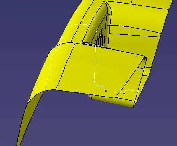
Then I have created the lines for the surfaces that would cause problems during ejection from the mold. and then I will bisect the line to get the tooling clear for y-direction. here i will neglect the fillet areas and will create the lines for the surfaces which are not perpendicular to the dummy tooling axis which i created.
The lines are shown below:
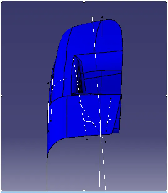
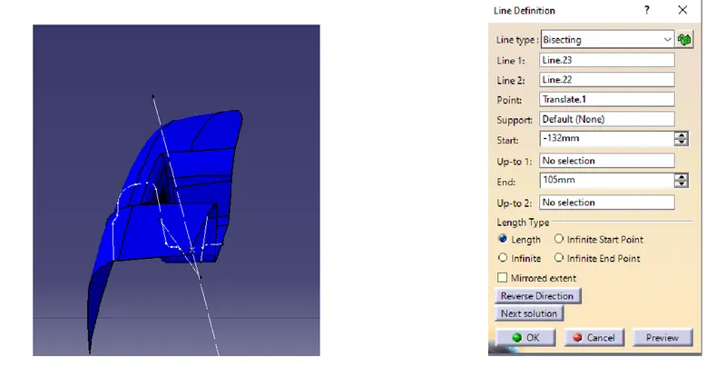
Then the lines which I have created by bisecting line. I will bisect them again to get the tooling clear for y-direction. the tooling clear in y-direction parameters are shown below:
Then similar thing i will do for the X direction. So again i will create the intersection but this time i will create between the XZ plane of the axis system and the class A surface. The intersection is shown below:

So again here i will create the lines for the surfaces which are not perpendicular to the dummy tooling axis i created and i will bisect the lines. The lines are shown below:
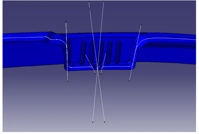
Then I will bisect the lines to get the tooling clear for x-direction. The tooling clear is shown below:
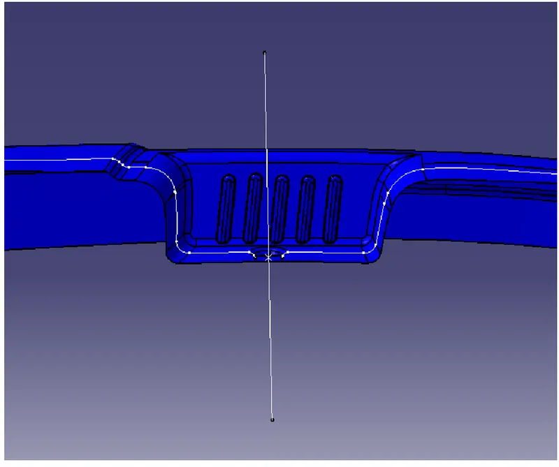
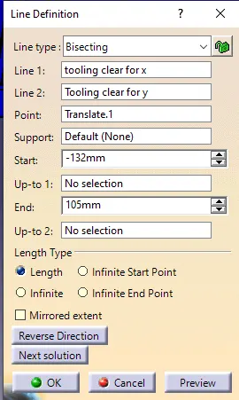
Then i will create one final bisecting line bisecting the two lines which are the tooling clear in x and tooling clear in the y-direction and that line will be my main tooling axis. The tooling axis parameters are shown below:
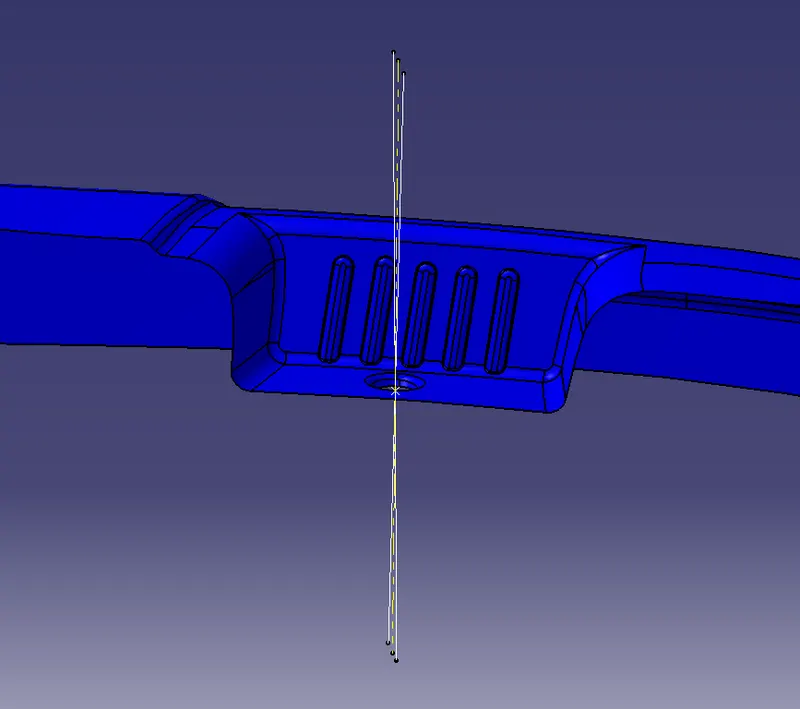
The main tooling axis is shown below:
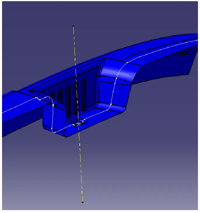
But the Class A surface will not clear with one tooling axis. The portion which is shown below will cause the problems
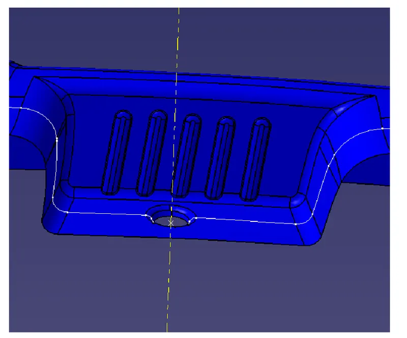
So for this, I have to create a separate tooling direction that will kind of perpendicular to the main tooling direction. So that the tooling axis will be for the side core. So for creating that tooling axis i will extract the back wall surface the extract is shown below:
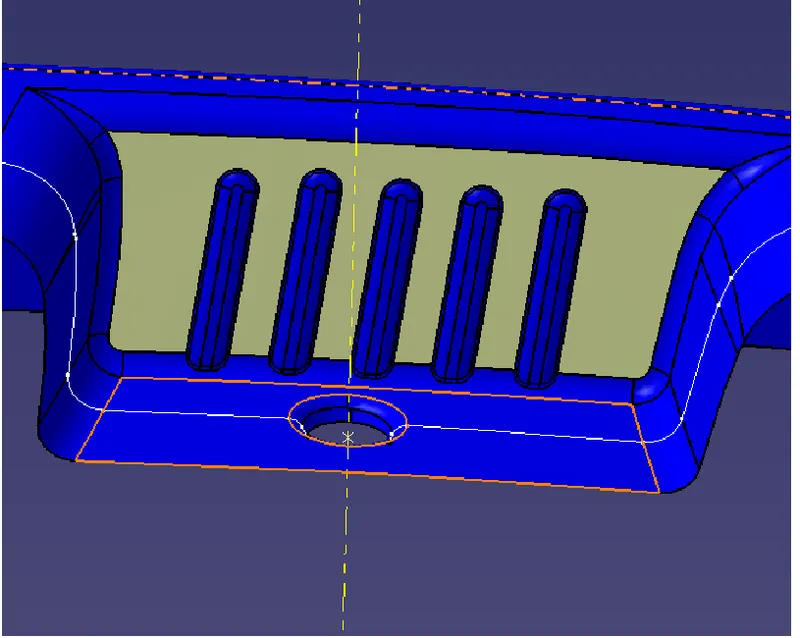
And then will create one random point on the extracted surface. and then create a line from that point along the y-direction. The line is shown below:
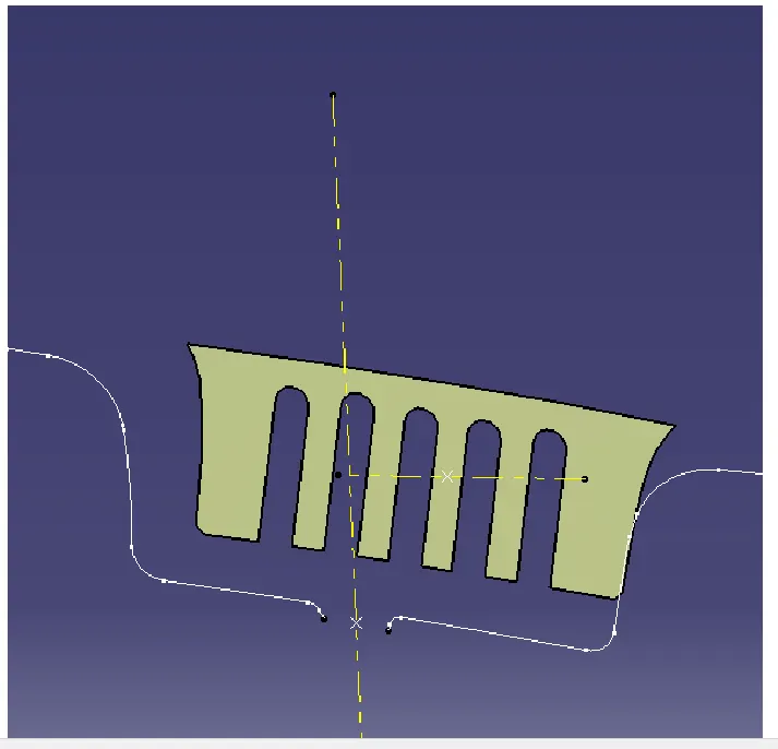
So this line will be my tooling axis for the side core. Which I will orient according to the draft once i do the draft analysis.
so after creating the tooling axis i will do the draft analysis.
Draft analysis - Draft analysis is a technique to analyze whether the component created is manufacturable or not based on the draft conditions applied. So here i will provide the direction in which the component should be ejected to get the easy removal. My dirction will be the tooling axis that i have created.
The minimum draft value for the Automotive plastic component is 3 degrees and those for the texture faces 7 degrees od draft is suitable. The draft is provided to the component for easy removal from the mold in case of the plastic components.
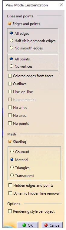
So here i will change the customize view parameters and will select the material mode.
Then I will go insert and select the analysis and in the analysis, I will select the draft analysis. The draft analysis block is shown below:
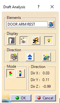
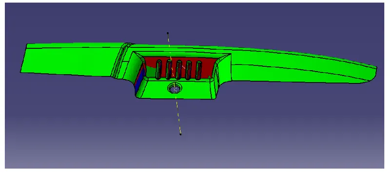
In the above fig. under the display, section selects the color scale and turn on the light effect for proper visualization. then under the direction section, i will click on the compass and will drag the compass from vehicle zero to my tooling axis. and then I will click on the lock feature and will select the class a surface. here my first dirction will be the main tooling axis The result is shown below:
The color scale is shown below:
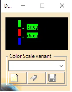
In the above fig. The Green color shows that the draft provided is more than 2.9 degrees
The Red color shows that the draft provided is between 0 and 2.9 degrees
The Blue color shows that the draft provided is negative.
But in that fig. u can see that the ribs portion and sidewall portion is not clearing so for that i will do the draft analysis but this time the tooling direction will be the tooling axis for the side core. so the result of that is shown below:
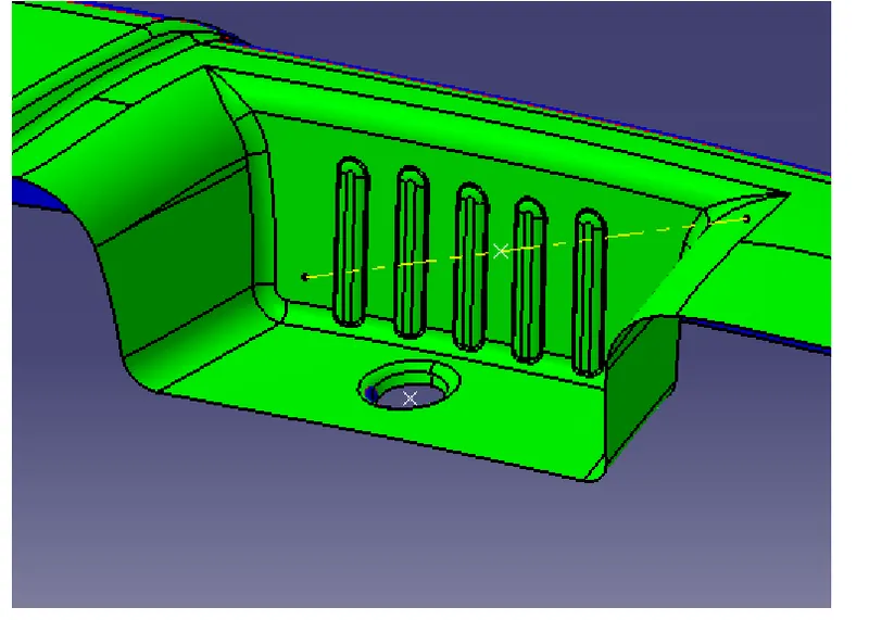
So now the portion that is not clearing with the main tooling axis is now cleared with this tooling axis.
So now I can say that for the class A surface the minimum draft provided everywhere is 3 degrees and now I can create the B and C surfaces from the class A surface.
CLASS B SURFACE - It is a surface that gives thickness from class A surface. All the supporting features of the component will be formed on the B surface only. so we can say that Class B is an engineering surface and Class A is an aesthetic surface.
For creating the B surface first i will insert a geometrical set and name it as B surface creation. i will start by extracting the surfaces so first, I will extract the rest surface. The extract is shown below
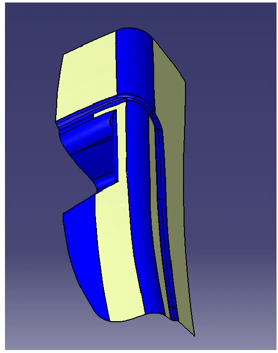
Then after i will do the extrapolate and after extrapolating i will offset the surface 2.5 mm because 2.5 mm is the thickness that i want. The offset is shown below:
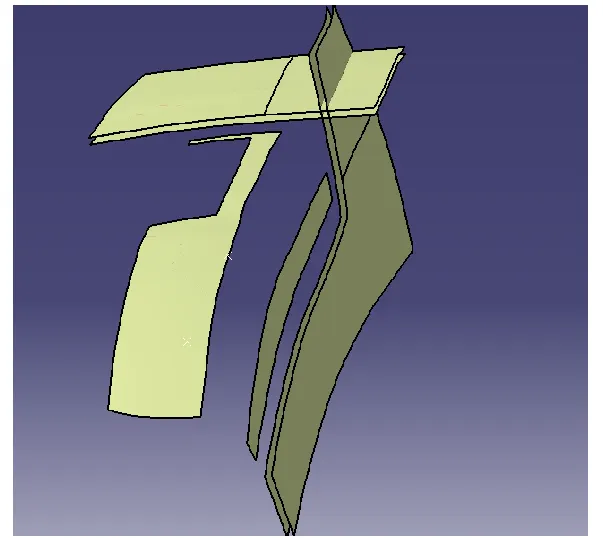
Then i will trim and will provide the fillet
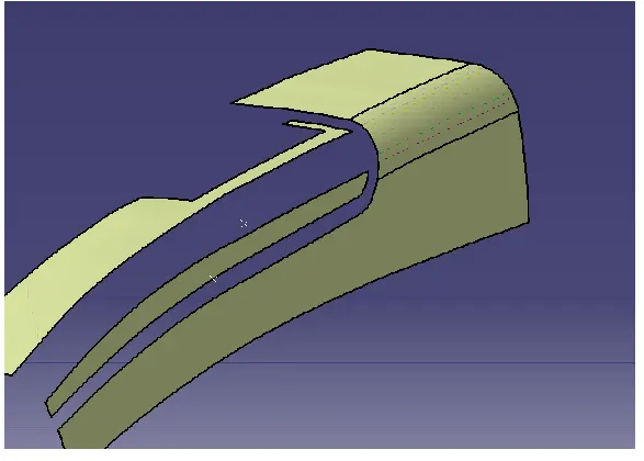
then i will do the same for the lower side also. that is will untrim and extrapolate and then trim and will provide the required fillet.
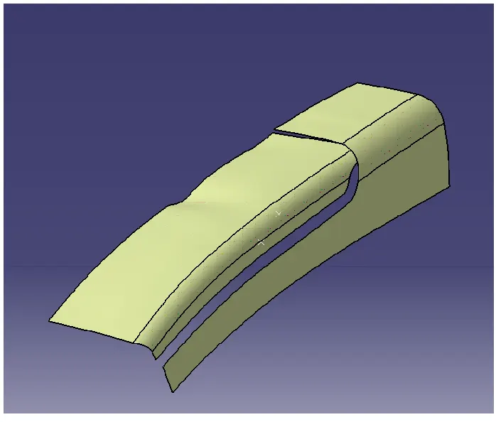
Now to fill that gap I will create one point on the class A surface and will insert an axis system on that point and create one sketch. The sketch is shown below:
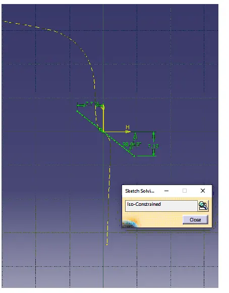
and i will create one smooth curve from the class A surface. the smooth curve is shown below:
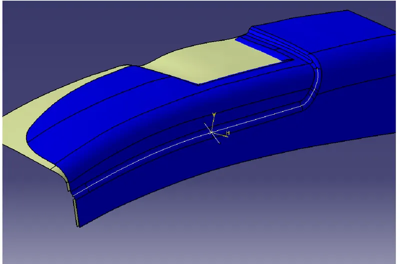
Then i will do one sweep using the smooth curve and the sketch i have created the sweep parameters are shown below:
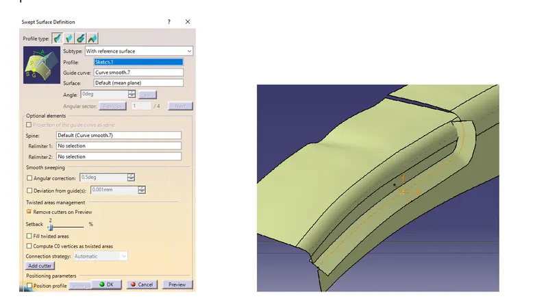
Then i will extract one more surface from the class A surface and will untrim it. The extract surface is shown below:
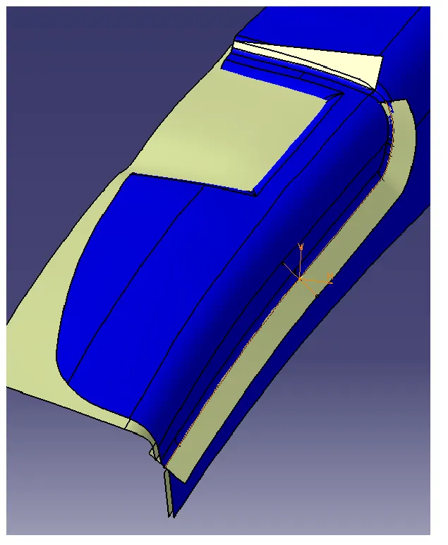
And i will create multi-section surface and fill that gap
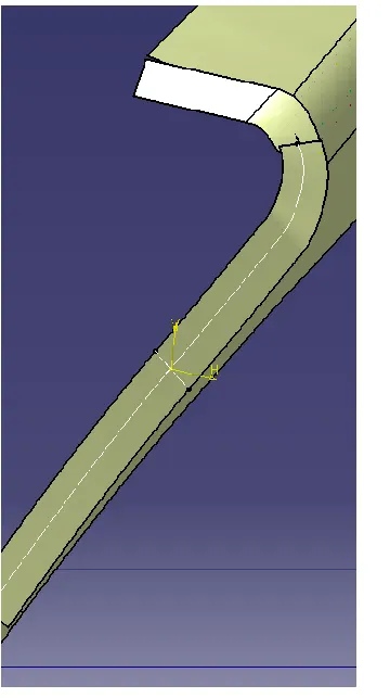
Then after joining and extrapolating the surfaces, i will do the trim. the trim is shown below:
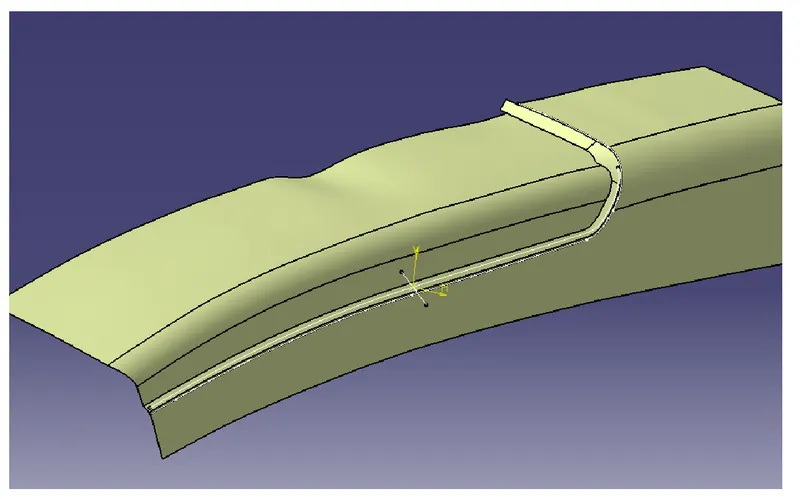
And finally, i will provide the required fillet for that swept area to get the whole upper rest surface
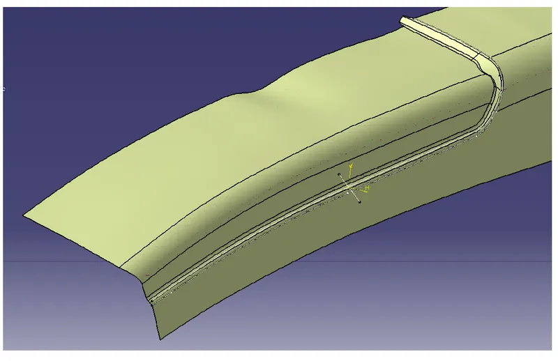
Then i will create those sidewalls using the same procedure as I did for the upper surface. so again will extract the surface and extrapolate it and then offset the surfaces to 2.5 mm
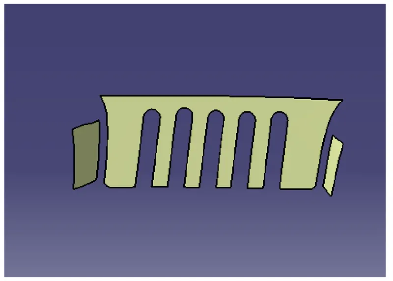
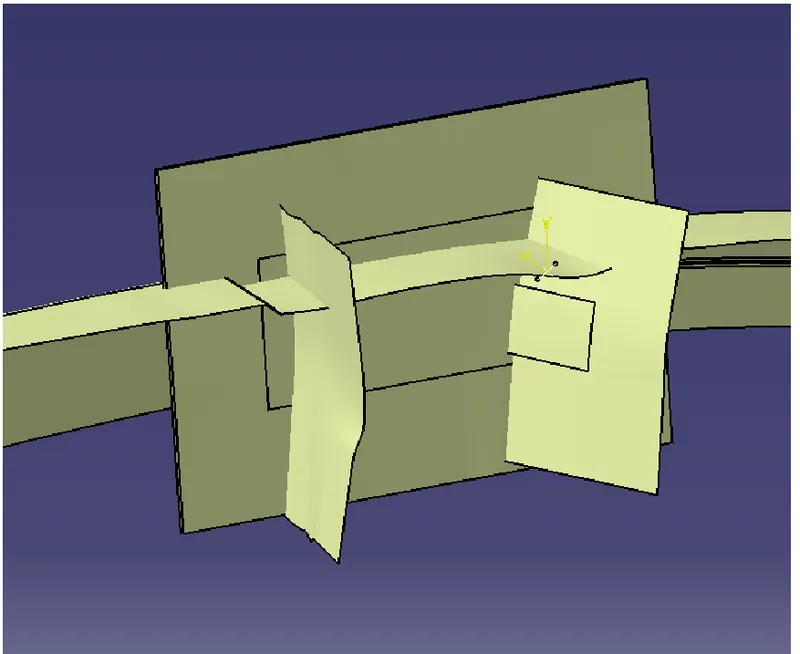
Then i will do the trim
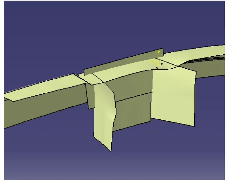
Then i will create the base following the same procedure that is extract untrim extrapolate and offset to 2.5 mm
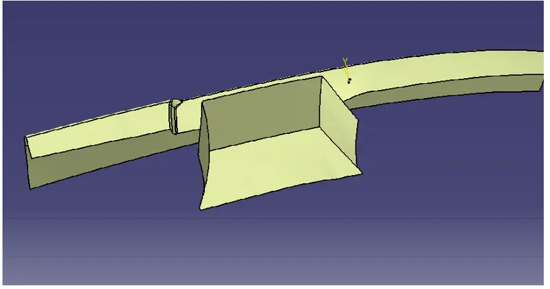
then i will provide the required fillets to get the desired class B surface. The class B surface is shown below:
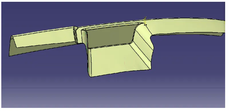
After the creation of the class B surface, i will create the class C surface
CLASS C SURFACE - Class C surface is defined as the surface which connects the CLASS A and CLASS B SURFACE along the tooling direction. The tooling direction here will be my tooling axis.
For creating the C surface first i will first create the smooth curve of the back surface. Then i will create the sweep. The sweep is shown below:
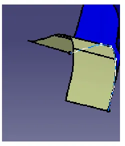
Then i will do the same for the front side that is i will create the smooth curve by extracting the surface and will sweep it. The sweeps are shown below. The sweeping direction will be the main tooling axis.
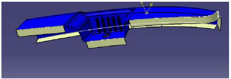
Now i will join the surfaces using the multi-section surface. The multisection surface is shown below: I will do that to both sides.
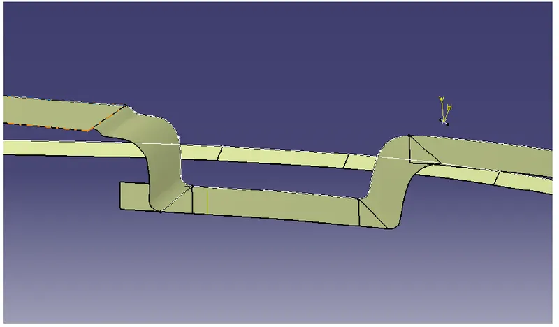
Then i will do the same for the sides also
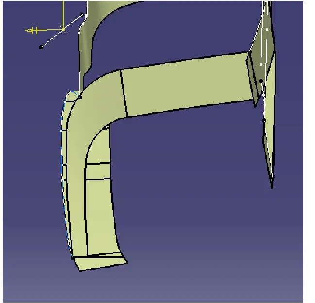
Then i will join the class A and class C surface. the join parameters are shown below:
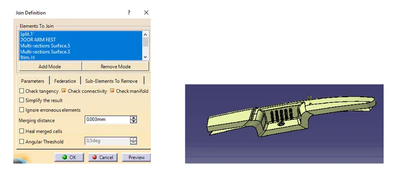
Then i will unhide my b Surface and do the final trim
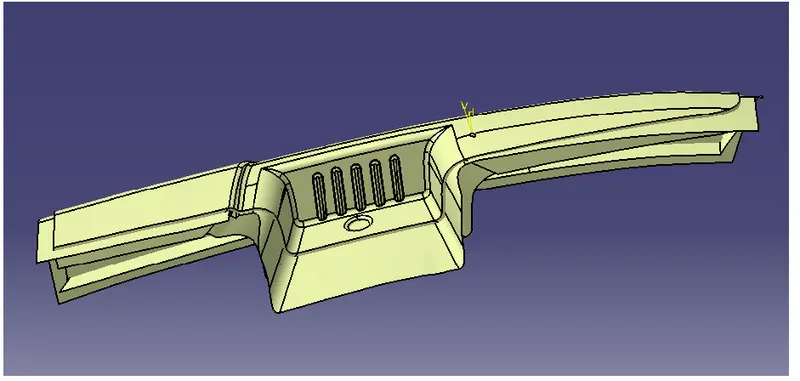
The trim will be between the join of class A and class C and the B surface. After doing the trim the result is shown below:
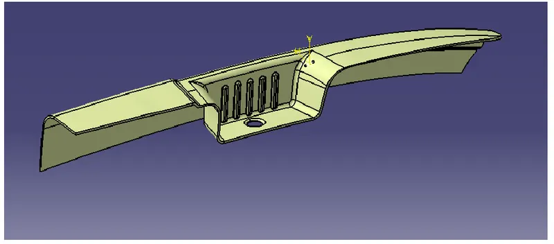
I will get my thick surface so now in part design i will create the solid body from this closed surface. The solid body is shown below:
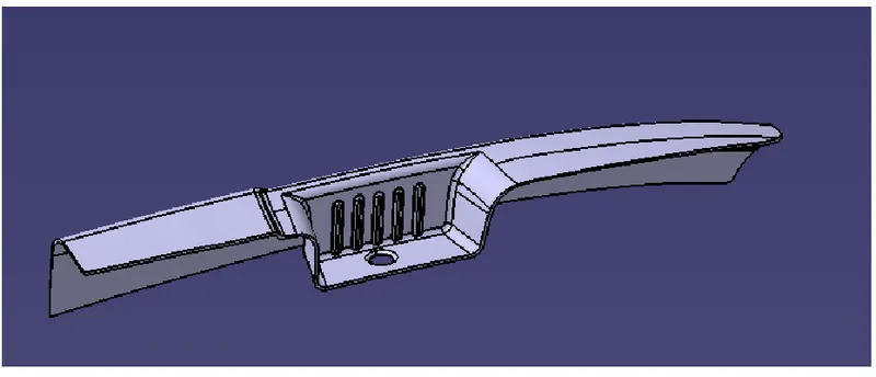
Now again i will do the draft analysis but this time for the whole solid body. so again here i will do two draft analysis first one for the main tooling axis and the second for the side core tooling axis.
The first draft analysis using the main tooling direction is shown below:
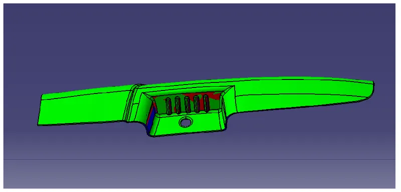
The color scale is shown below:
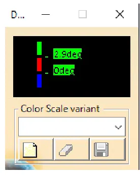
In the above fig. The Green color shows that the draft provided is more than 2.9 degrees
The Red color shows that the draft provided is between 0 and 2.9 degrees
The Blue color shows that the draft provided is negative.
So here u can see that the middle portion is still not clear so I will clear it using the tooling axis for the side core. The result of that is shown below:
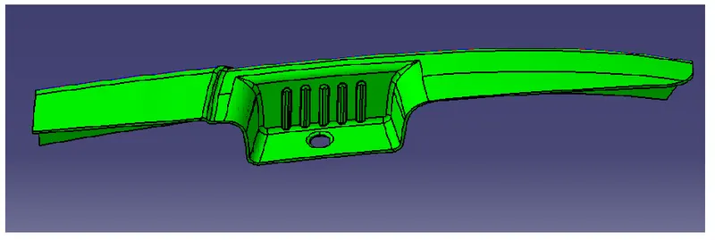
So now u can see that the ribs and wall portions are cleared. so now I can say that my part is manufacturable.
RESULT - The creation of the door armrest is done and the result of the draft analysis is shown below:
First using the main tooling axis:
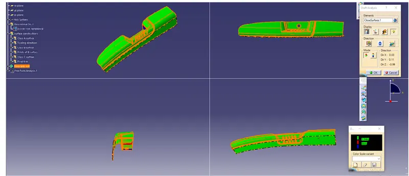
Now using the slider tooling dirction or the tooling axis for the side core:
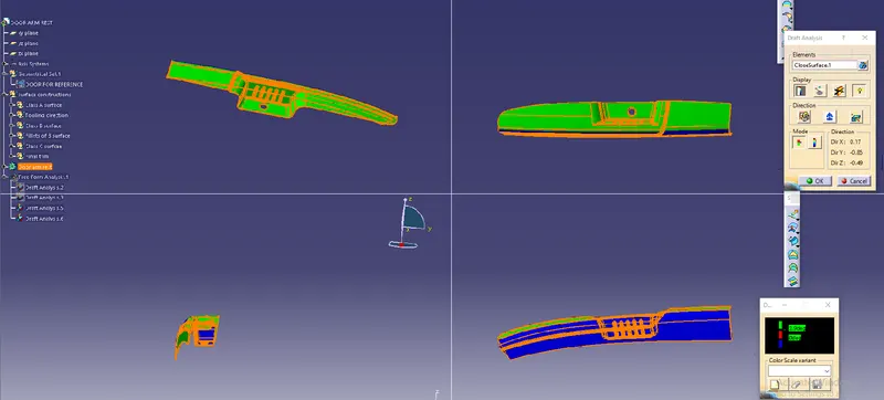
CONCLUSION - This concludes the creation of the door armrest part and the draft analysis on that part.