Week-6 Challenge: EV Drivetrain
AIM - To perform the tasks that are given to me.
GOVERNING EQUATION - To calculate the steady state speed i know the condition that the vehicle Torque and Motor Torque should be equal
in the given condition the Vehicle Torque is given by the equation

For the Motor Torque i know the formulae
Tm = ((K`phi`*Vs)`div`Ra) - (((K`phi`)^2*w)`div`Ra)
Here Km = motor constant
Vs = supplied voltage or armature voltage
Ra = Armature resistance
w = is the satic speed that i require
The speed for motor and vehicle will be equal than only static state condition will occur.so i will equate both and find the value of the static speed.
OBJECTIVES - 1) To describe about the type of power converter circuits employed in hybrid and electric vehicles.
2) To find out the Ev steady state speed if the duty cycle is 70%.using the following values that are given to me
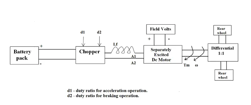
Rated Armature voltage= 72 V
Rated armature current= 400 A
Ra= 0.5Ω, KΦ= 0.7 Volt second
Chopper Switching frequency= 400 Hz
3) To explain about the author's perspective about the blog on Induction Versus DC brushless motors by Wally Rippel, Tesla.
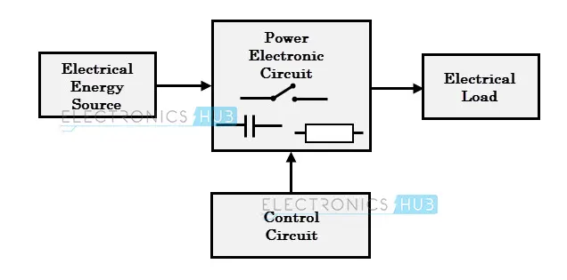
PROCEDURE - For the first part - The purpose of using the power converters is to process and control the flow of electric energy by supplying voltages and currents in a form that is optimally suited for user loads.Due to the high power handling with higher efficiencies, these converters become an integral part of industrial electric drives, high electric power supplies, electric traction systems and automobile control equipments.
The block diagram of power electronic converter is shown below:
There are basically 4 different types of power converters used:
1) AC - DC converter
2) DC - AC converter
3) DC - DC converter
4) AC - AC converter
Here i Have to explain about the converters that are used in hybrid and electric vehicles. The AC - AC converter is not used in hybrid and electric vehciles rest other type of converters are used.
1) AC - DC converter or Rectifier - An AC to DC converter is also called a rectifier, which converts AC supply from main source to DC supply for the load.The essential components in this rectifier include transformer, switching unit, filter and a control block.
Here, the transformer adjusts the primary AC source supply to the input of rectifier stage. Usually it is a step-down transformer that reduces the supply voltage to a circuit operating range.The output of the rectifier is of pulsed DC and hence it is filtered using filter circuit, which is usually made with a capacitor or a choke.So in hybrid and electric vehicles the rectifier will recharge the batteries comming from the motor/generator.
2) DC - AC converter or inverter - These converters are connected between DC source of fixed input, and variable AC load. Most commonly, these DC to AC converters are called as inverters. An inverter is a static device that converts fixed DC supply voltage to variable AC voltage.Here the fixed DC voltage is obtained from batteries or by DC link in most power electronic converter.
The output of the inverter can be variable/ fixed AC voltage with variable/fixed frequency.These can be single phase or three phase inverter depending on the supply voltage. These converters are mainly divided into two groups. One is PWM based inverters and other multilevel inverters.So in hybrid and electric vehicles the inverter will give the power to motor/generator from the battery.
3) DC - DC converter - A DC - DC converter is also called chopper.A DC chopper is a static device that converts a fixed input DC voltage to variable DC output or a fixed DC output of different magnitude (which can be lower or higher) than input value.
The chopper circuit is connected between DC input source and DC load. This chopper consists of power electronic switching devices such as thyristors which are connected in such a way that they produce required DC voltage to the load.
The output voltage is controlled by adjusting ON time of the thyristor (or switch) which turn changes the width of DC voltage pulse at the output. This method of switching is called as pulse width modulation (PWM) control. They are divided into 3 types
- step - down chopper - A step-down chopper produces an average output voltage lower than the input DC voltage.
- step - up chopper - In this chopper, the output voltage is always greater than input voltage.
- Buck/Boost chopper - This chopper can be used both in step-down and step-up modes by continuously adjusting its duty cycle.
Here the DC - DC converter will provide the power to the vehicles auxillaries like (lights,radio,etc.) from the battery.
For the second part - For this purpose i have to calculate the Ev static state speed.
The speed torque characteristics of vehicle and motor is shown below
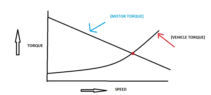
In the graph above the red point shows the steady state speed of the vehicle and it is the intersection of motor torque and vehicle torque.
so now i know the condition when the static speed will occur. The condition is that the Motor torque and Vehicle torque should be equal.
(TORQUE)vehicle = (TORQUE)motor
(Torque)vehicle is given by equation
(Torque)motor is given by following formulae
(T)m = ((K`phi`*Vs)`div`Ra) - (((K`phi`)^2*w)`div`Ra)
The imputs that are given to me are as follows:
Rated Armature voltage= 72 V
Rated armature current= 400 A
Ra= 0.5Ω, KΦ= 0.7 Volt second
Chopper Switching frequency= 400 Hz
here the duty cycle at which i have to calculate the static speed is given to me as 70%
so, Vs = (Armature voltage)*(duty cycle)
Vs = 72*0.7 = 50.4V
putting all the value in motor equation
(T)m = ((0.7*50.4)`div`0.5) - ((0.7)^2*w)`div`0.5)
(T)m = 70.56 - 0.98w
Now, the vehile torque is given by
`T)v = 24.7 + (0.0051)w^2`
equating both (T)m and (T)v
`24.7 + 0.0051w^2 = 70.56 - 0.98`
the above equation will form a quadratic equation as
`0.0051w^2 + 0.98w - 45.86 = 0`
To find the value of w i will use following formulae
w1,w2 = `-b +- frac{root()(b^2 -4ac)}{2a}`
in my equation a = 0.0051 , b= 0.98, c= -45.86
so i will put the values and find w1,w2
w1,w2 = `-0.98 +-frac{root()(0.98^2-4*0.0051*45.86)}{2*0.0051}`
the values after solving the above equation are as follows:
w1 = 38.823 rad/sec
w2 = - 230.98 rad/sec
Here iam not considering the regenerative speed so i will neglect the value of w2. so my value for static speed for EV is 38.23 rad/sec.
For the third part - The blog Induction Versus DC brushless motors by Wally Rippel, Tesla is about the comparison induction motor and DC brushless motor used in electric and hybrid vehicles. In his blog he has told about the principles of operation of both the motors and he told about the advantages and disadvantages of using them.
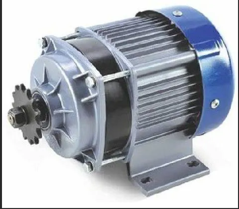
Brushless DC motor is shown below:
The 3 phase AC induction motor is shown below:
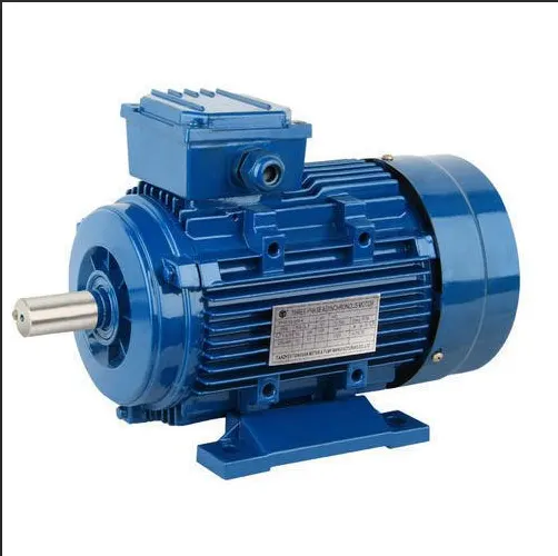
The comparison that he made in his blog is described below:
Firstly, he talked about the construction of motors. The induction motor rotor has no magnets just stacked steel laminations.Where as the brushless DC motor rotor has permanent magnets.
The supply of induction motor is AC 3 Phase and the supply of brushless motor is DC supply. The control strategy used for induction motor is that it does not requirs any use of inverter which converts the DC - AC means it can run directly on 3 phase power. But for Brushless motor a inverter is needed to vary stator currents to generate rotating magnetic field and to control it.
The induction motor can generate starting torque when connected to fixed frequency supply but the brushless DC motor cannot generate that starting torque.In case of induction motor the rotor heating is more due to eddy currents.But in case of Brushless motor the rotor heating is less and can be cooled.
The efficiency of the induction motor he stated in his blog was 85% and that of brushless motor was close to 100% which is higher than the induction motor.The magnetic field can be varied in case of induction motor but it cannot be varied in case of brushless motor. The losses in Brushless motor increases with increase in size of machine where as in case of induction motor the losses does not increase with increase in size of machine.
The cost of Brushless motor is high due to cost of permanent magnets used in them,where as the cost of induction motor is less as compared to DC brushless beacuse of no permanent magnets used in them. The speed of the induction motor cannot be varied that is big disadvantage of using that motor where as in case of brushless motor the speed can ve varied and control using the inverter.
The conclusion the author made about the blog was that there was no clear winner in that comparison means both the induction motor and Brushless DC will work better in different cases.The brushless dc motor will continue to be used in hybrid vehicles, where as the induction motor will likely maintain its dominance for high performance pure electric vehicles.
RESULT - The EV steady state speed for duty cycle 70% was found to be 38.23 rad/sec.
CONCLUSION - All the tasks that are given to me has been completed successfully and the results are shown in result section.