Week 12:Project-1-Meshing of Door Inner Panel Challenge
AIM - To mesh the door inner panel following the element quality criteria given.
OBJECTIVE - To mesh the door inner panel component following the element quality criteria shown below and to assign the required thickness to the component.
Target Element Length = 4 Units
| S.N | Quality Criteria | Value |
| 1 | Aspect Ratio | 5 |
| 2 | Skewness | 45 |
| 3 | Warping | 15 |
| 4 | Taper | 0.5 |
| 5 | Min. Length | 2 Units |
| 6 | Max. Length | 6 Units |
| 7 | Min angle Quad | 45 |
| 8 | Max angle Quad | 135 |
| 9 | Min angle Tria | 20 |
| 10 | Max angle Tria | 120 |
| 10 | Tria % |
10 |
INTRODUCTION - The door panel will usually match the rest of the vehicle's interior. Door panels were formerly made of cardboard with an upholstered interior finish of vinyl, leather, cloth, carpet, or other materials for the decorative trim. Modern cars typically have door cards made of plastic, most often using injection molding, as well as incorporating other decorative materials.
The design should incorporate both the necessary service amount and the functional unit (such as "it is strong" and "it looks and feels good") so that a given car door panel "would service a car body's life span of 200,000 kilometers (124,274 mi)." The door panel typically incorporates other parts that contribute to the appearance, functionality, and ergonomics of the vehicle. These include armrests, switches, or other controls for windows and the locking mechanism, convenience lights, Map pockets, lower substrate, storage compartments, and other features. An image of the door trim panel is shown below:
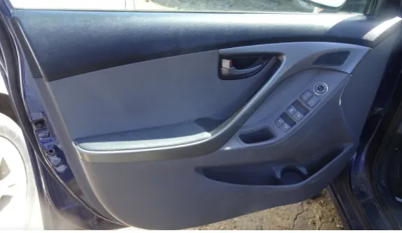
Here as we know the door inner panel is a plastic component. so the meshing will be plastic meshing. Plastic meshing is a type of shell meshing where the thickness of the component varies. In plastic meshing, the mid-surface extraction plays a vital role. Because the thickness of the component varies auto mid surface cannot be used. So we have to go for manual mid surfacing.
There are some terms that are important for the quality criteria are:
warpage - whenever we have a quad element in two different planes then we will have the element failing for warpage. Ideally, the element should be in a single plane, when they are in two different planes and if we split the quad along the diagonal and measure the angle between the normals it will give the element warp angle.
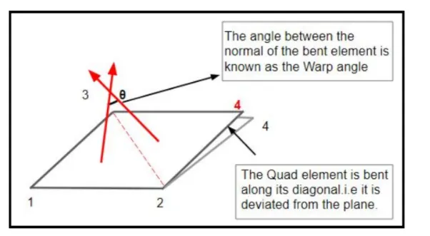
skewness - skewness is the quality of elements in terms of angle. For a quad element the skewness will be:
skewness = 90 - (θmin)">(θmin)(θmin)
Aspect ratio - The aspect ratio is the ratio of maximum length to the minimum length. when you see a quad element one side smaller than the remaining three sides then the element will fail for aspect ratio.

Jacobian - The deviation of the element from the ideal shape is measured through jacobian. The ideal value of jacobian is 1.
PROCEDURE - I will start by importing the geometry as a door inner panel component is given to me. so for importing the geometry, I will go to import and select the file. The model is shown below:
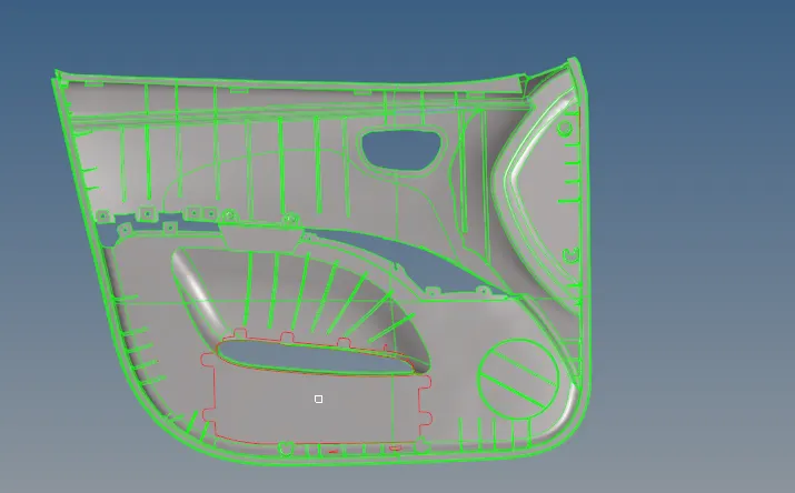
Then I will split the component into different parts and work on them separately. For splitting, I will go to the surface edit and under that will select the surfaces and direction along with it has to split. The components after splitting are shown below:
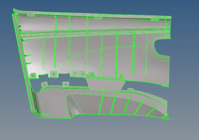
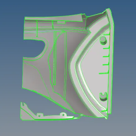
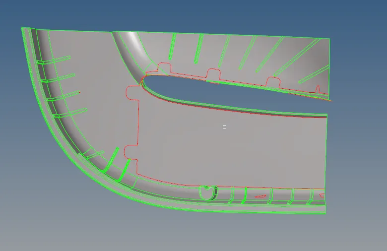
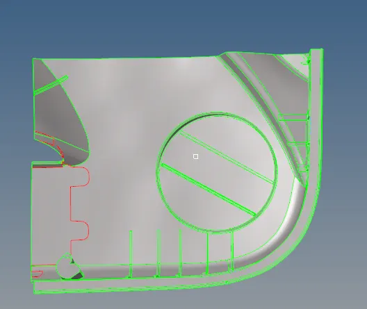
As we can see above the door panel is split into 4 components and now I will extract the mid surface and mesh the components individually.
First taking the lower right half portion of the door inner panel. Here for all the components, I will have to extract the mid surface manually. In the component, there are some B-side features like ribs, locators, and dog house so it has the fillets which are to be removed from the geometry because they can cause the element failures. so for defeaturing, I will go to defeature command under geometry section. and select the surfaces I have to feature specifying the radius. The component after defeature is shown below:
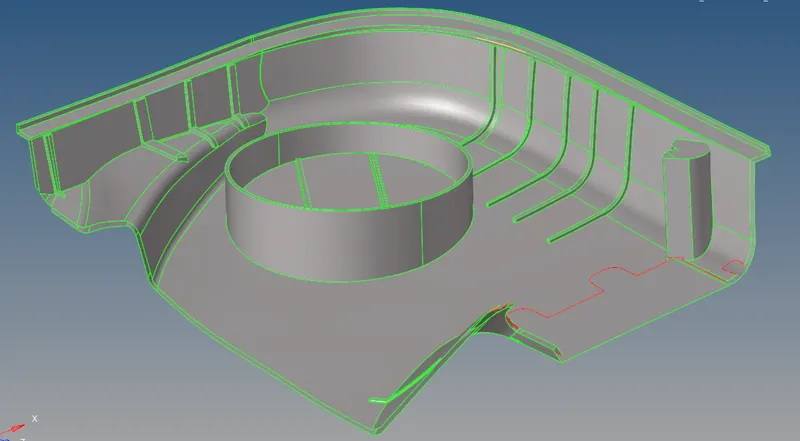
Then I will extract the manual mid surface of the component by offsetting the surfaces at the center. For doing that I will go to surface edit then offset then select the surfaces I have to offset specifying the value at which it needs to be offset. We can use the surface pair option to extract the mid surface of the ribs. The extracted mid surface should be extended to the bottom base surface using the extend option in surface edit. There is one more way for extracting the mid surface of the rib that is through the 'mid line' option. create the midline using the surface edge of two surfaces then trim that line with the base surface and then finally create a new surface using the midline and trim line extending to the base surface. The mid surface of the component is shown below:
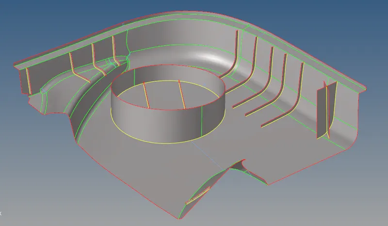
Now the mid surface is extracted properly and now I will mesh the component. For meshing, I will use batch meshing under the auto mesh. But before meshing I will create the parameter file and criteria file because according to that only the mesh will be created. The criteria file and parameter file are shown below:
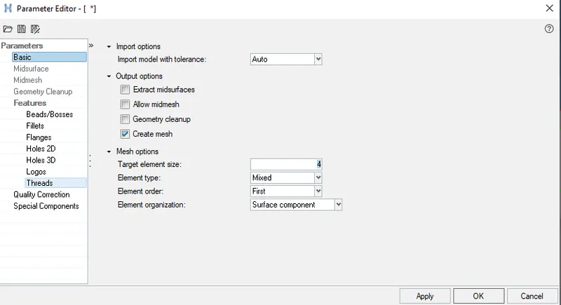
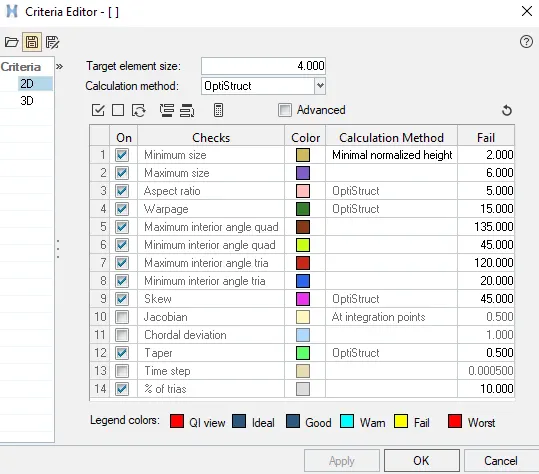
The mesh of the component is shown below:
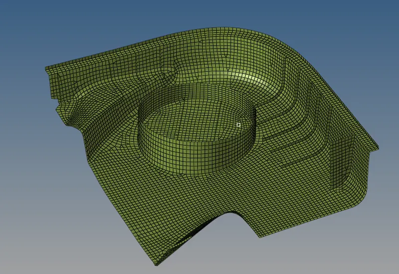
After the meshing is done I have to check for the element failures. so for that, I will to tool and then check elements and see which are the elements failing and will rectify those element failures. For rectifying the element failures I will use the following commands.
- Drag tria command under the quality index
- Remesh the elements for clearing the element failures
- Element optimization under the quality index
- place node command under the quality index
- Translate command to translate nodes. This command will be under the tool section
- smooth command which will smooth the mesh and ultimately remove the element failures
- Element edit command to split, create and combine elements.
so using the above-mentioned command I will clear the element failures. The final mesh of the lower right half of the door inner panel free from any element failures is shown below:
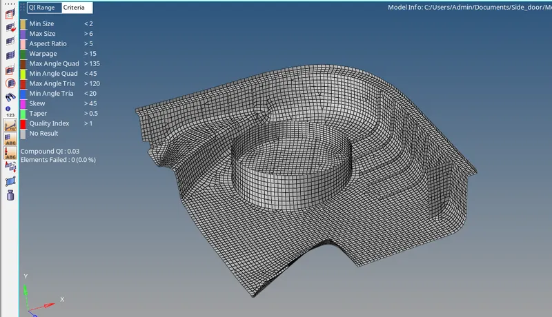
now I will move on to the lower-left half of the door inner panel. The parent geometry is shown below:
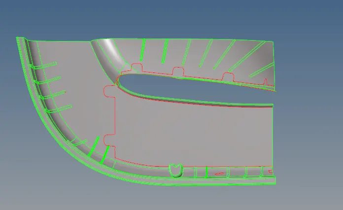
so again I will follow the same procedure as I did earlier which is defeating the fillets and extracting the mid surface of the component manually. The mid surface of the component is shown below:
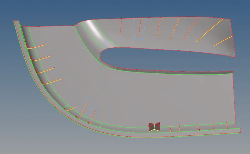
After the mid-surface extraction, I will mesh the component using the batch mesh under the automesh panel under the 2 D section. The mesh of the component is shown below:
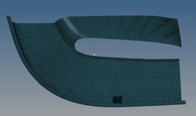
After the meshing is done I have to check for the element failures. so for that, I will to tool and then check elements and see which are the elements failing and will rectify those element failures. For rectifying the element failures I will use the following commands.
- Drag tria command under the quality index
- Remesh the elements for clearing the element failures
- Element optimization under the quality index
- place node command under the quality index
- Translate command to translate nodes. This command will be under the tool section
- smooth command which will smooth the mesh and ultimately remove the element failures
- Element edit command to split, create and combine elements.
so using the above-mentioned command I will clear the element failures. The final mesh of the lower-left half of the door inner panel free from any element failures is shown below:
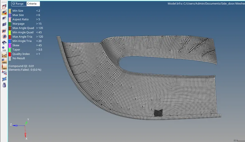
now I will move on to the upper right half of the door inner panel. The parent geometry is shown below:
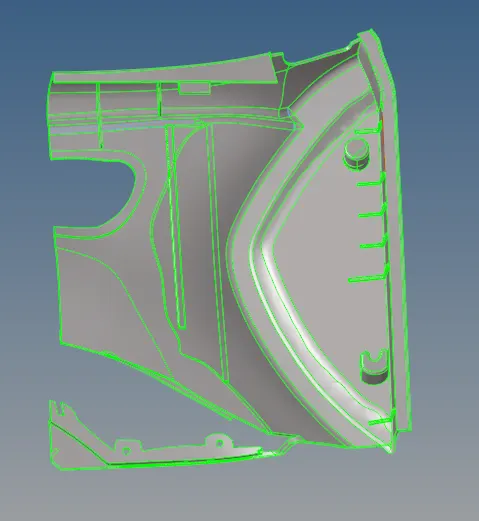
so again I will follow the same procedure as I did earlier which is defeating the fillets and extracting the mid surface of the component manually. The mid surface of the component is shown below:
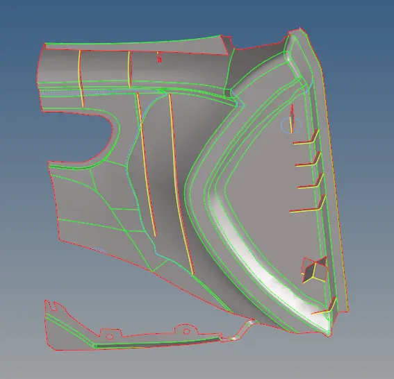
After the mid-surface extraction, I will mesh the component using the batch mesh under the automesh panel under the 2 D section. The mesh of the component is shown below:
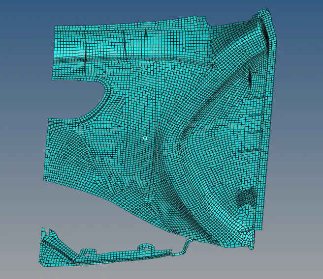
After the meshing is done I have to check for the element failures. so for that, I will to tool and then check elements and see which are the elements failing and will rectify those element failures. For rectifying the element failures I will use the following commands.
- Drag tria command under the quality index
- Remesh the elements for clearing the element failures
- Element optimization under the quality index
- place node command under the quality index
- Translate command to translate nodes. This command will be under the tool section
- smooth command which will smooth the mesh and ultimately remove the element failures
- Element edit command to split, create and combine elements.
so using the above-mentioned command I will clear the element failures. The final mesh of the upper right half of the door inner panel free from any element failures is shown below:
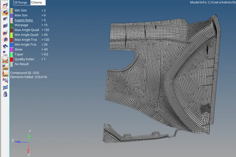
Now I will move on to the final component that is the upper left half of the door inner panel. The parent body is shown below:
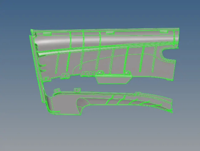
The mid surface extracted manually after defeaturing the geometry is shown below:
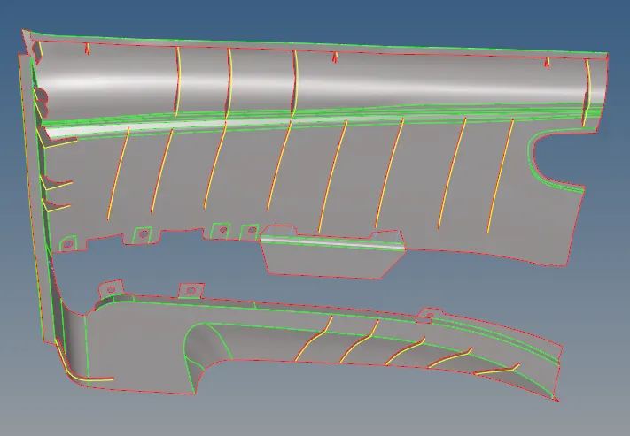
After the mid-surface extraction, I will mesh the component using the batch mesh under the automesh panel under the 2 D section. The mesh of the component is shown below:
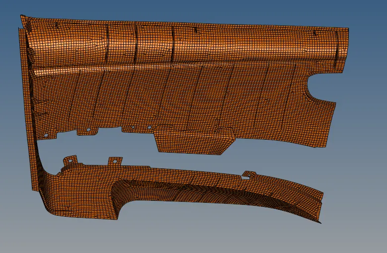
After the meshing is done I have to check for the element failures. so for that, I will to tool and then check elements and see which are the elements failing and will rectify those element failures. For rectifying the element failures I will use the following commands.
- Drag tria command under the quality index
- Remesh the elements for clearing the element failures
- Element optimization under the quality index
- place node command under the quality index
- Translate command to translate nodes. This command will be under the tool section
- smooth command which will smooth the mesh and ultimately remove the element failures
- Element edit command to split, create and combine elements.
so using the above-mentioned command I will clear the element failures. The final mesh of the upper left half of the door inner panel free from any element failures is shown below:
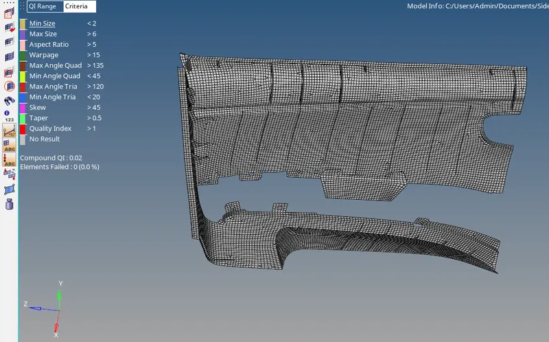
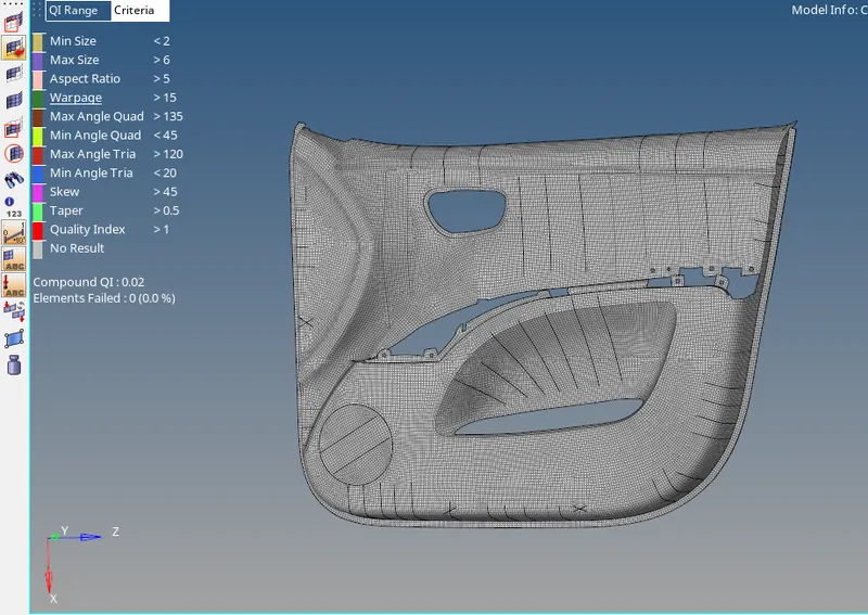
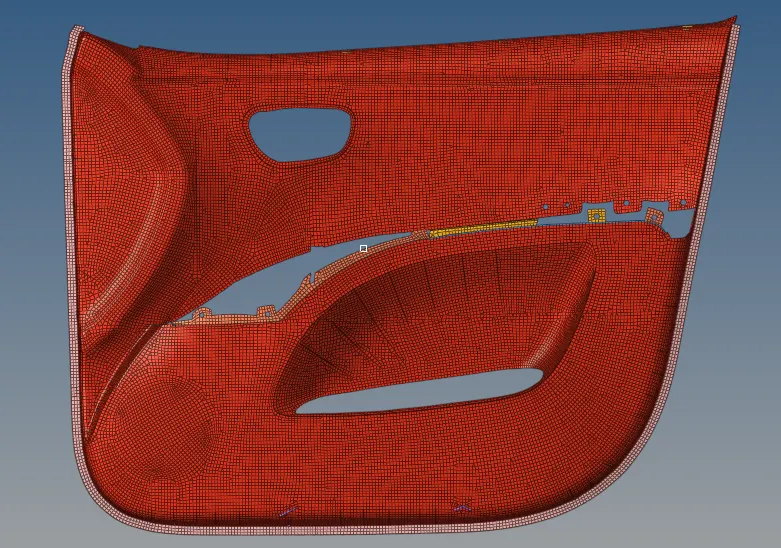
Now meshing of individual components is done and now I will keep all the elements and all the components that I have split earlier in a single component. Here one thing I have to ensure is the connectivity of all the elements in one component. The mesh of all the components combined free from element failures is shown below:
Now I have to assign the thickness to the component. So for that, I will use the auto thickness method. For that I will go to the mesh menu on the top then assign then will click on mid mesh thickness a map midmesh thickness window will pop up as shown below:
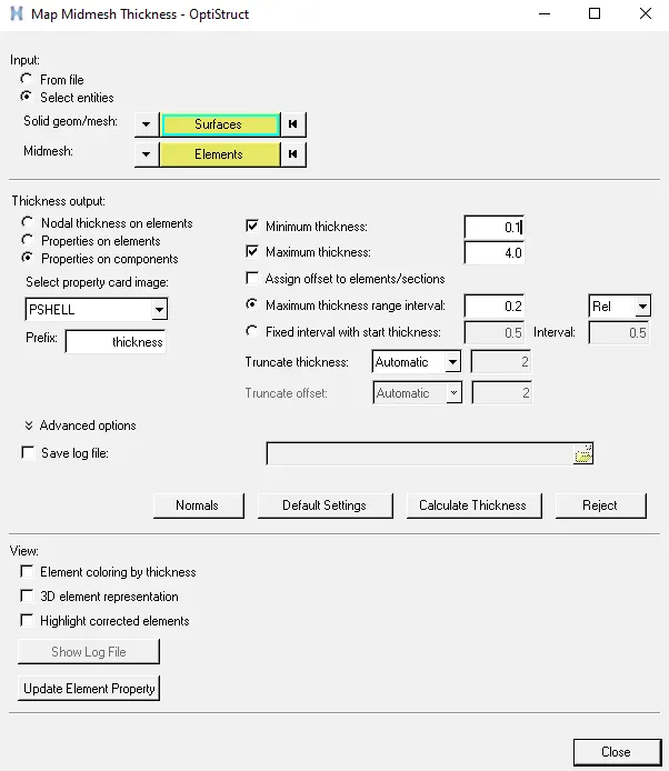
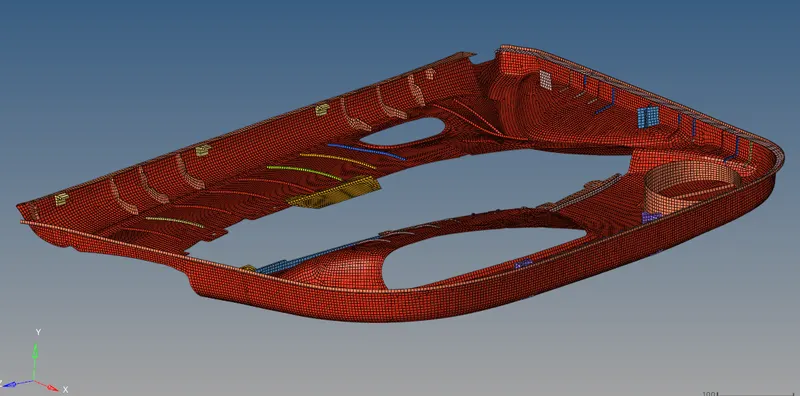
Here as we can see it is asking for surfaces and elements. so I will select all the surfaces of the parent body and all the elements that are in one component. Then finally I will click on calculate thickness. HyperMesh will generate the automatic thickness for the component. The thickened component is shown below:
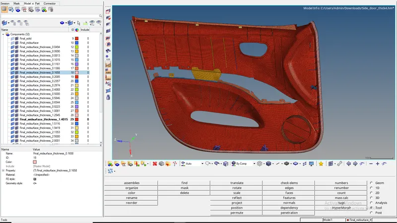
RESULT - The mesh of the door inner panel after assigning the thickness is shown below:
CONCLUSION - The meshing of the door inner panel has been completed successfully and the thickness was also assigned to the mesh.