Roof challenge
AIM - To design the Roof creating its essential flanges and reinforcements using the roof styling given as the input.
INTRODUCTION - An automobile roof or car top is the portion of an automobile that sits above the passenger compartment, protecting the vehicle occupants from sun, wind, rain, and other external elements.
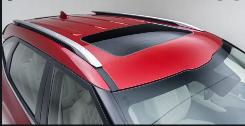
The types of roofs are:
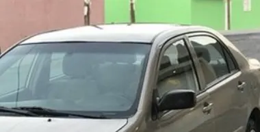
1) Hardtops - When we talk about hardtops, we refer to the common rigid forms of automobile roofs we see around. This type of roof is made from metal or plastic in modern-day cars. So, the common Toyota Corolla, Camry, and many of the cars in Nigeria are all Hardtops.
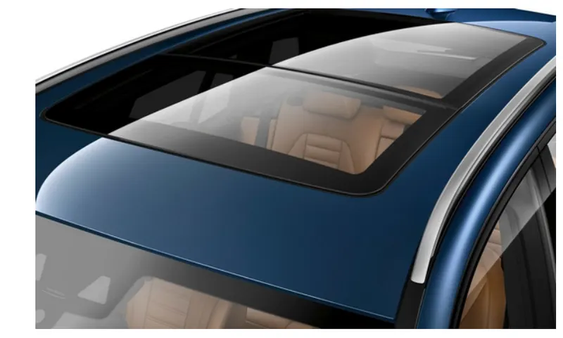
2) Sunroof - A sunroof is an operable type of roof that allows for an opening in the roof of an automobile; say a window in a roof. It can allow either light or air or both to enter the vehicle. They are either operated manually or automatically.
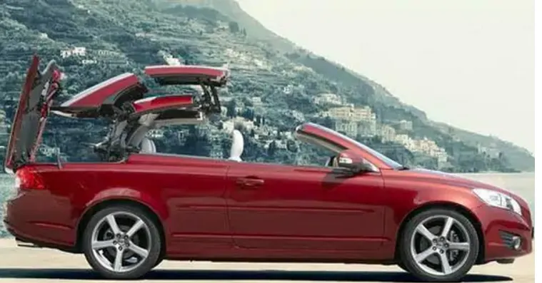
3) Convertibles - convertibles are passenger cars that can be driven with or without the entire roof in place. They have first introduced as open-air vehicles; no roofs, no sides.
Under the styling surface of the roof. Other structures contribute to its strength and stability. They are mainly installed on the flatter surface of the roof. The other structures that lie inside the roof are:
- Front roof rail - Front roof rail is used to provide strength to the roof panel and it also acts as a link between windshield glass, roof panel, and headliner. Headroom clearance and visibility criteria should be considered the important factor while designing the front roof rail
- Bow roof - Bow roofs are again the roofs that will provide support to the roof panel by increasing its strength. The position of the bow roofs is the very factor that needs to be considered. The bow roofs should be straight.
- Center roof rail - This is a roof rail that will at the center of the roof to provide strength and stability to the roof. The center roof rail will be a straight roof rail.
- Rear roof rail - Rear roof rail is again used to strengthen the roof and this acts as a link between the roof panel and the backglass which is connected to the backdoor of the car.
PROCEDURE - Here first I will work on the upper part of the Roof which is the styling surface. I will be creating the ditch area. The ditch area is the extended portion of the main roof concealed by other BIW panels. The rail supports are attached to the ditch area using spot welds. So here also the main factors we have to consider are Headroom clearance, visibility criteria, clearance for windshield and backdoor.
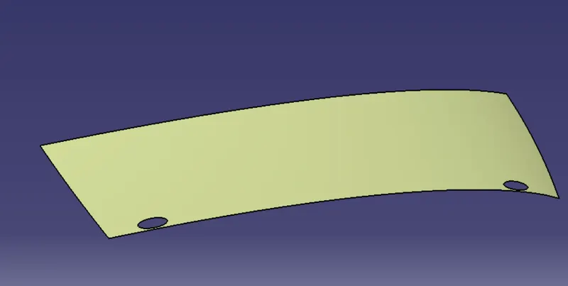
So for creating the upper part I will extract the half surface from the input which I have to work on. The extracted surface is shown below:
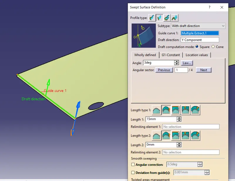
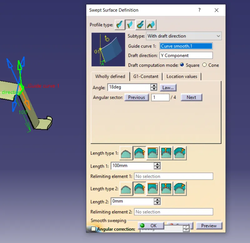
Then I will create the ditch area for the front end so I will extract the front edge and sweep it with a draft angle for 3 degrees because the tool opening area should be 3 degrees that are a requirement. The sweep is shown below:
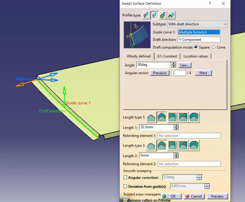
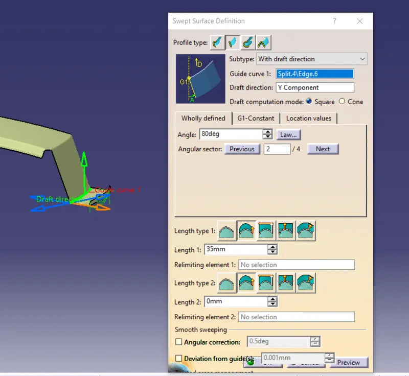
Then again I will use the sweep command to make the flange. the sweep is shown below:
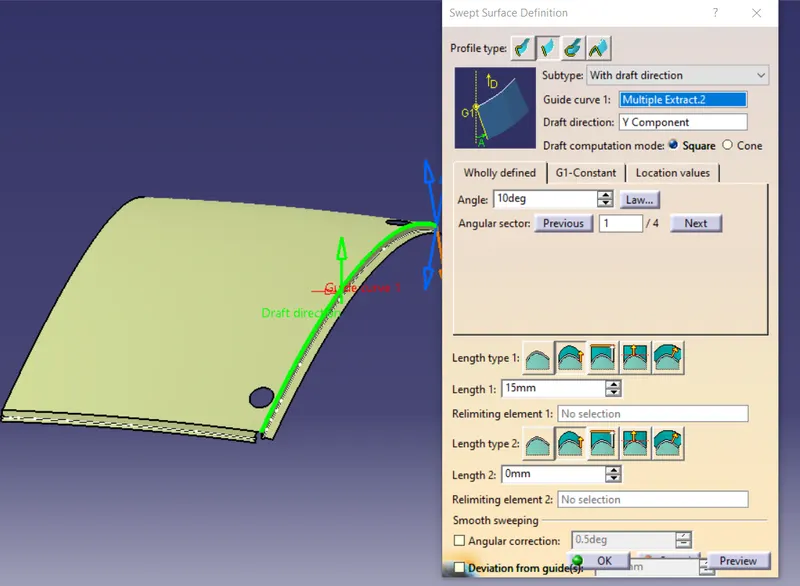
Then similarly I will create the flanges on the sides also. For other flanges, the draft will be above 7 degrees. The side flanges are shown
now I will create the ditch area for the backside also. So I will extract the edge and sweep it to create the flanges.
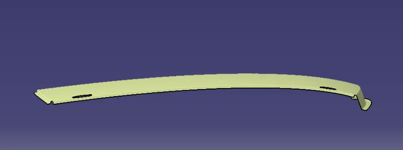
Then I will join the surfaces together and provide the required fillets. The upper part after providing the fillets looks like this:
Then I will create the embosses on the roof. Embosses again will increase the strength of the hood. So for creating the embosses I will create one sketch and project it on the roof surface and then split it but before splitting it I will extract the surface of the roof so that I offset it later. Then I will sweep the projected sketch with a draft angle of above 7 degrees. The sweep is shown below:
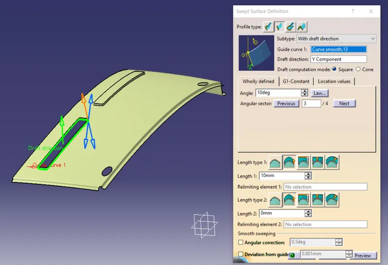
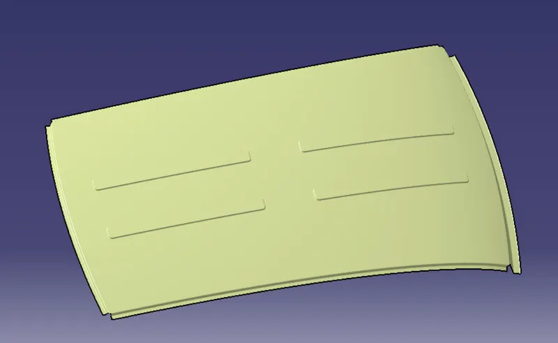
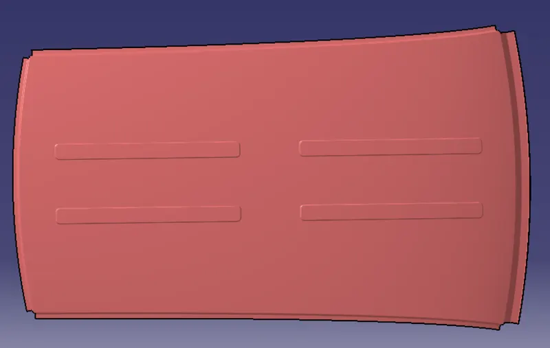
Then I will offset the extracted surface to 8mm and trim it with the sweep and then I will join the surface and provide the required fillets. I will then symmetry the roof to get the complete roof. The complete roof outer surface is shown below:
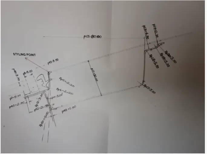
Front Roof Rail - Now after creating the Roof's outer surface I will create the front roof rail. The thickness of the front roof rail will be 0.75mm For the front roof rail. Spot welds are applied on the windshield end and another end is connected using the mastic sealant. I will follow the master section shown below:
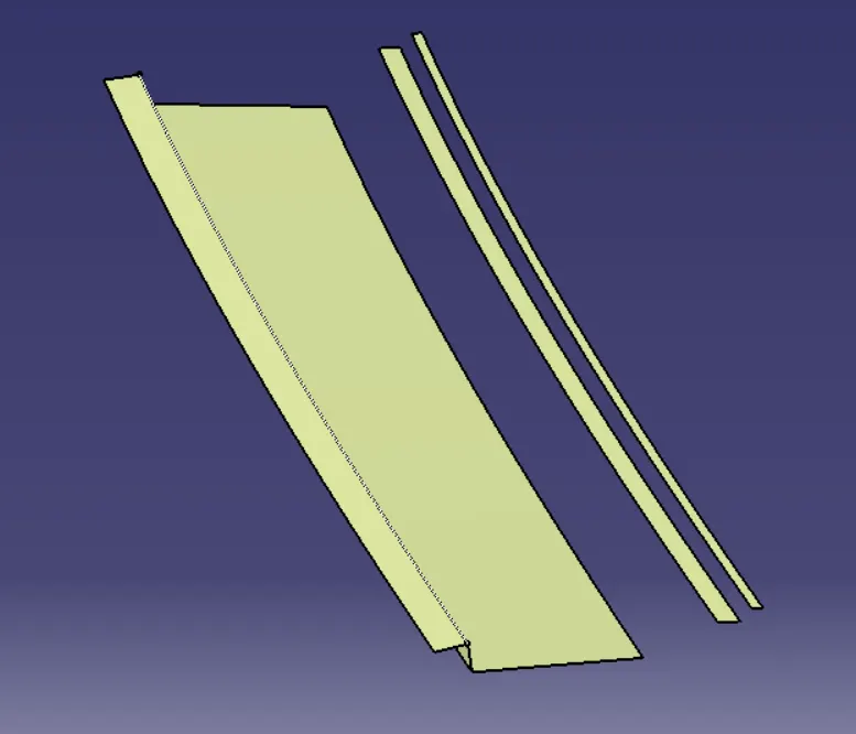
Using the Roof outer surface just created I will extract the surface and offset it to the required value that is 4.5 and 6.5 mm. and offset the flange surface to 1.5 mm. Then on the offset surfaces, I will offset the edges to the required value as per the master section and split it. And also I will use the sweep feature to create the surfaces. After splitting and sweeping the surface I have is shown below:
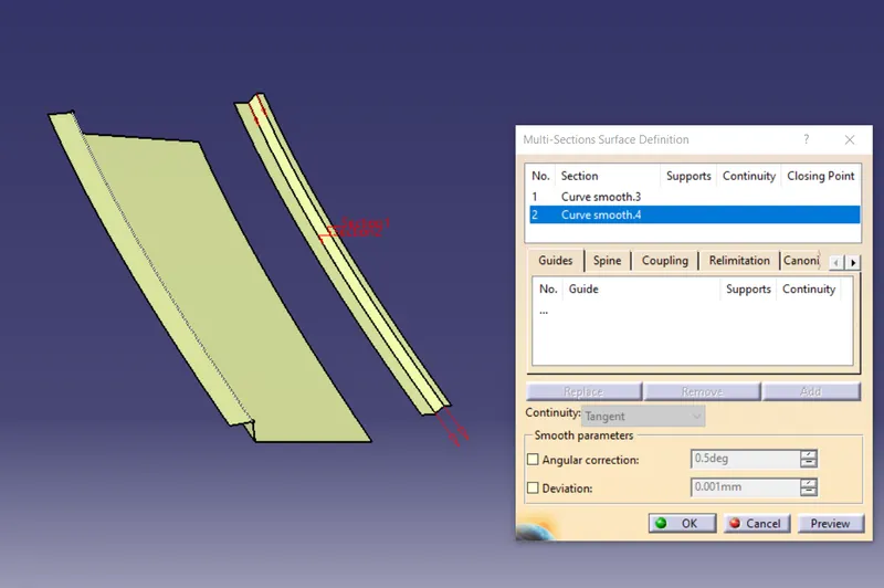
then I will use the multisection surface to join the splits and the swept surfaces The two multisection section are shown below:
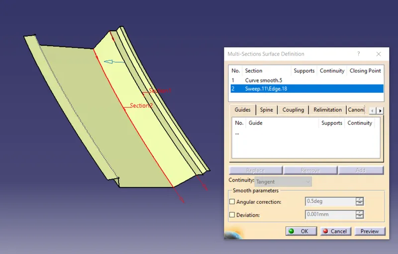
Then I will just join all the surfaces and provide the fillets as mentioned in the master section. The front roof rail after proving the fillets is shown below:
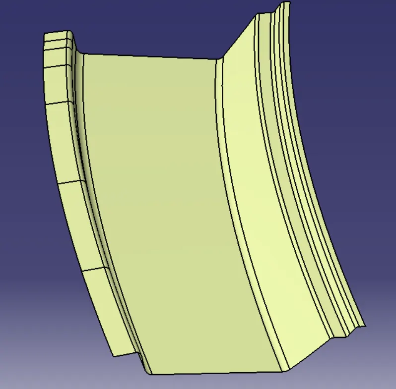
Then for the front roof rail also I will create the embosses following the same procedure as I did for the roof outer that is create the sketch, project it then split and sweep it later trim and provide the fillets. For embosses, there are no such rules and standards the only thing we have to keep in mind is to give them along the y-direction. The Front roof rail along with embosses is shown below:
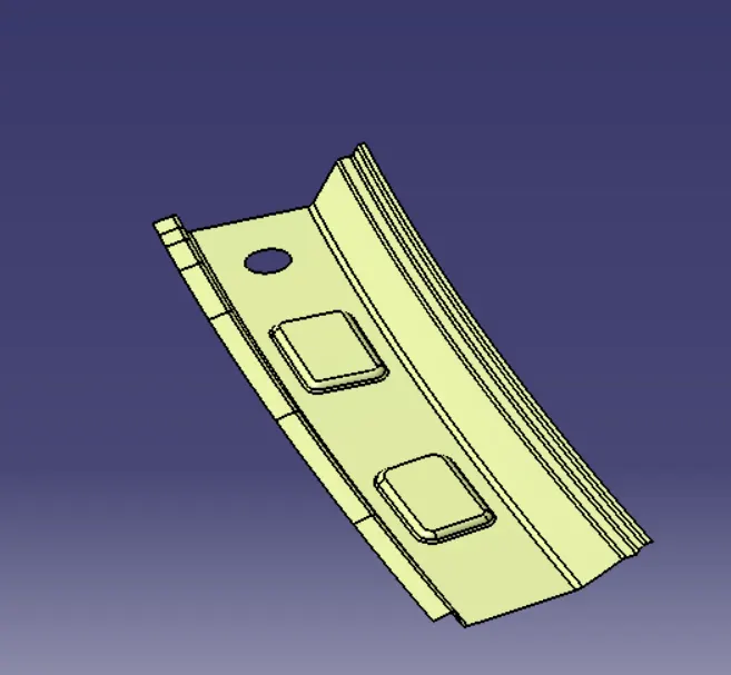
then I will just symmetry the front roof rail to get the complete surface. The complete front roof rail is shown below:
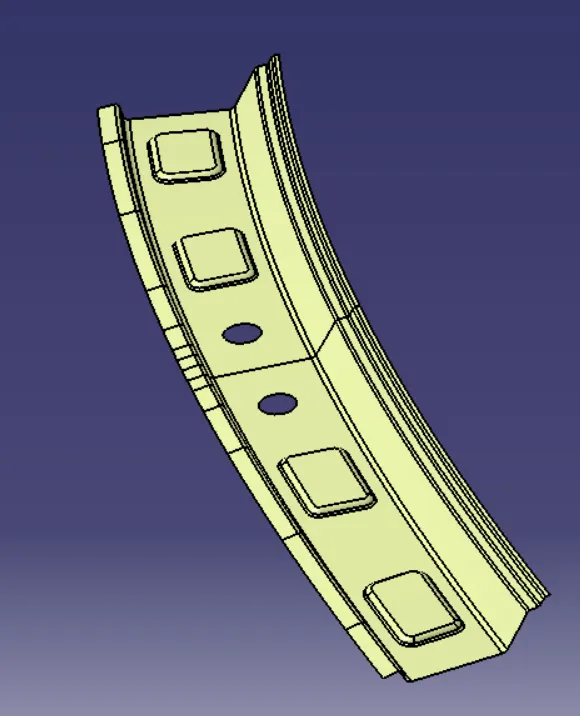
Rear Roof Rail - After creating the Ront roof rail I will create the rear roof rail. The rear roof rail as mentioned earlier is the connecting link between the backdoor and body side inner and outer panels. For designing this again we have to consider the headroom clearance and the visibility criteria of the driver. similar to the front roof rail one side of the rear roof rail will be connected to the backdoor through spot welds and the other side will be connected using the mastic sealants. For creating this I will follow the master section shown below:

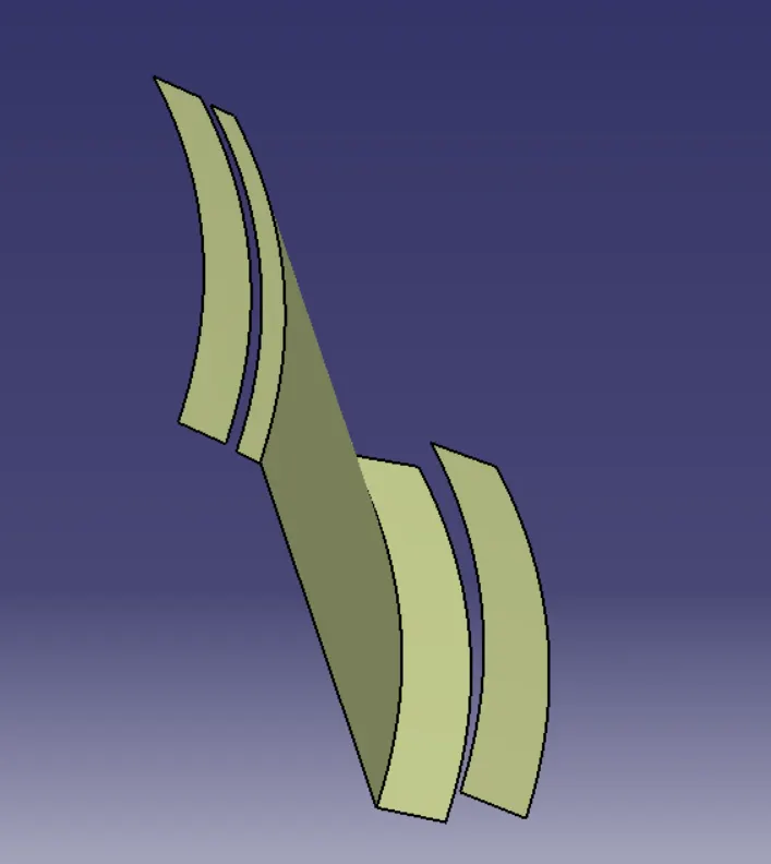
I will the similar procedure as I did for the front roof rail. I will offset the surfaces to the required value and split them and sweep the edges according to the master section The Rear roof rail after the offset, split and sweep is shown below:
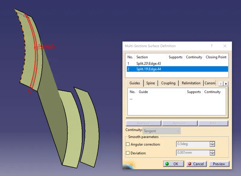
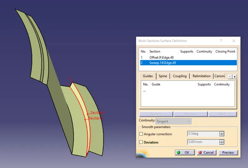
Then I will use the multisection to join the surfaces. The multi sections surfaces are shown below:
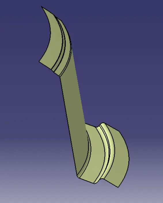
Then I will join the surfaces and provide the fillets as mentioned in the master section. The rear roof rail after providing the fillets is shown below:
Then for this also I will create the embosses following a similar procedure as I did earlier. The rear roof rail with embosses is shown below:
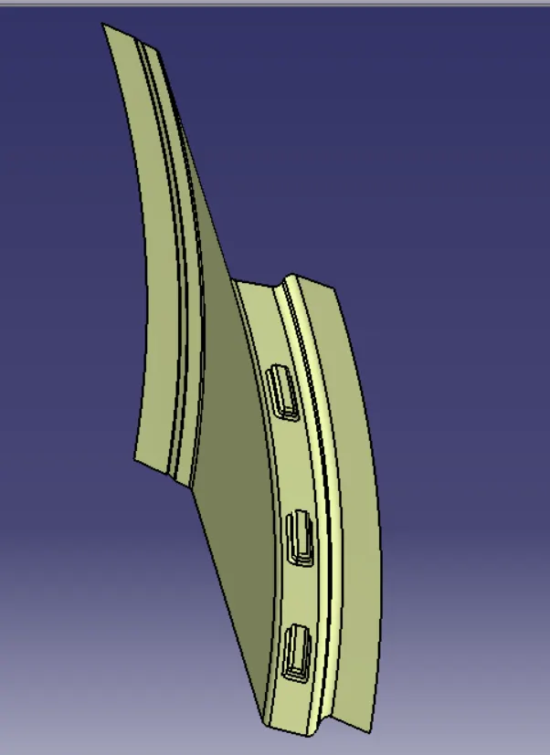
Then I will just symmetry the above surface to get the complete rear roof rail. The complete Rear roof rail is shown below:
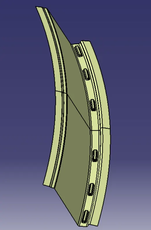
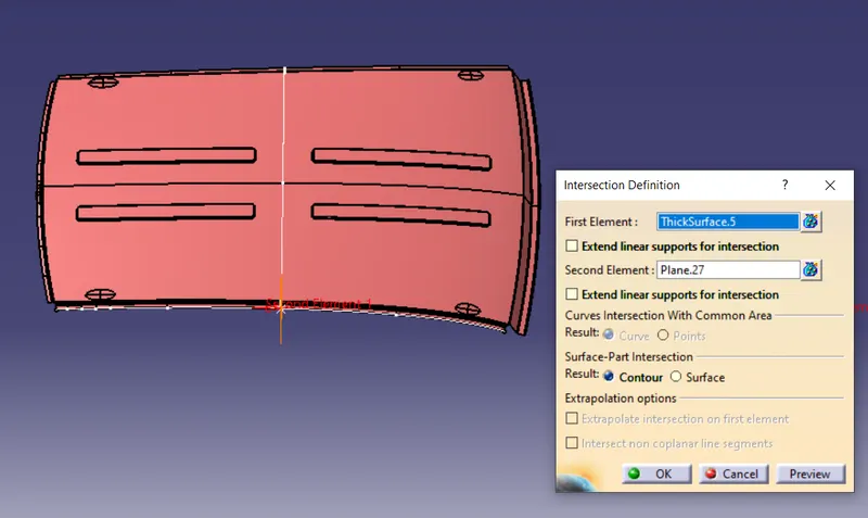
Center Roof Rail - After creating the Rear roof rail I will create the center roof rail. Again here the design criteria will be the same as it was for the front and rear but this roof rail will be straight. The thickness of the center roof rail will be 2.5 mm For creating the center roof rail again I will extract the upper surface of the roof and will create a point at the center of the edge and through that, I will create a plane parallel to the YZ plane and I will create the intersection to get the straight profile for the roof rail. The intersection is shown below:
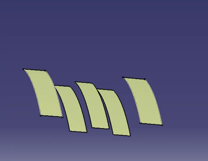
Then I will offset the extracted surface to 9.75mm, 25.5, and 19.5, and using the parallel curve feature I will offset the intersection to the required value and split it on the offset surfaces. The split surfaces are shown below:
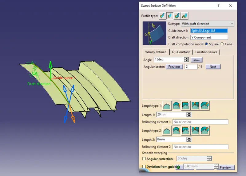
Then I will sweep the edges to join the surfaces. I will sweep the edges for more than 7 degrees of the draft. The sweeps are shown below:
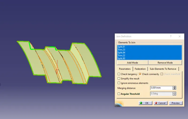
Then I will just trim the surfaces to get the required surface for the center roof rail and join the surfaces. The center roof rail after performing the trim and join operation is shown below:
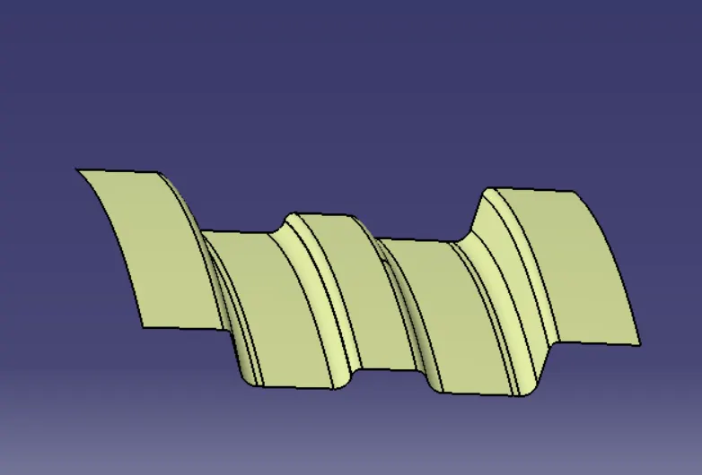
Then I will just provide the required fillets.
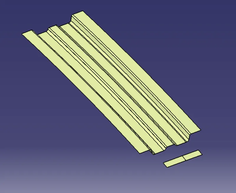
Now, this roof rail will be spot welded to the roof surface. so for crating that I will have to offset the side flange of the roof to the required value and split the required portion. The split is shown below:
Now I will use the multisection feature to join it. The multisection surface is shown below:
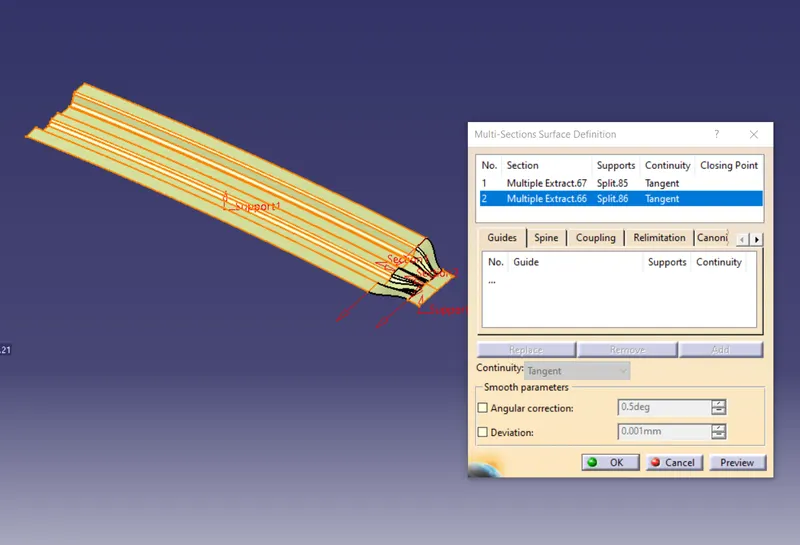
Then I will just join all the surfaces and symmetry them to get the complete center Roof rail. The complete center roof rail is shown below:
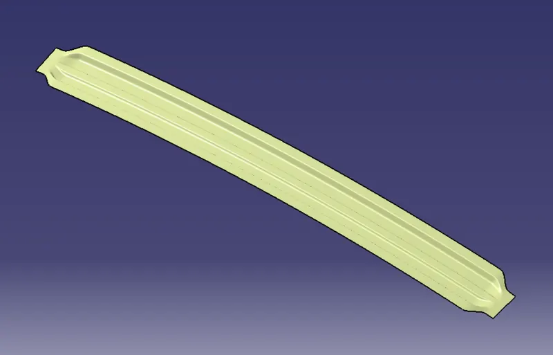
Bow Roofs - Now all the roof rails are completed and now I will create the bow roofs. so here I will be creating three bow roofs. The procedure for creating the bow roofs is similar to the center roof rail. so first I will create a center bow roof which will spot welded to the center roof rail. And it will be connected to the roof through mastic sealants, the mastic sealants again increase the strength of the roof. The thickness of the bow roofs will be 1.5 mm So again I will offset the extracted surface from the roof but here I will offset the surface in a way there is a 5mm gap for the mastic sealants, then I will just make the parallel curves and split it, sweep and trim and finally join it. The join is shown below:
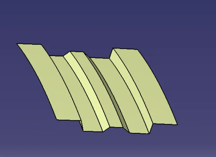
Then I will just the required fillets. The center bow roof after providing the fillets is shown below:
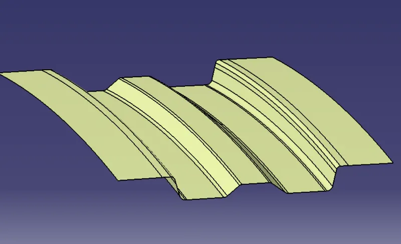
Now creating the mastic I will just create a sketch on the ZX plane and will project it on the bow roof surface. The projection is shown below:
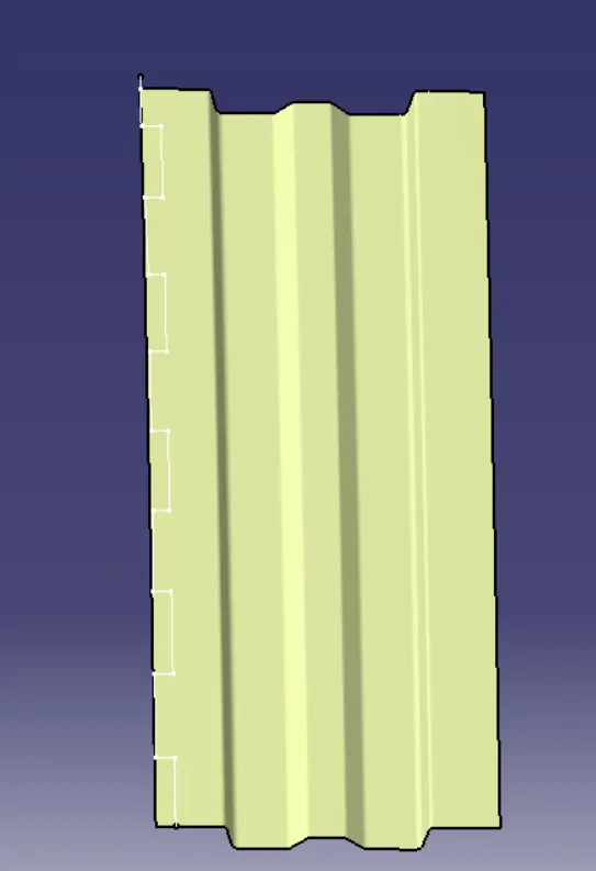
Then I will just split the projected sketch from the roof surface to get the space for the mastic sealants. The complete center bow roof surface after mirroring is shown below:
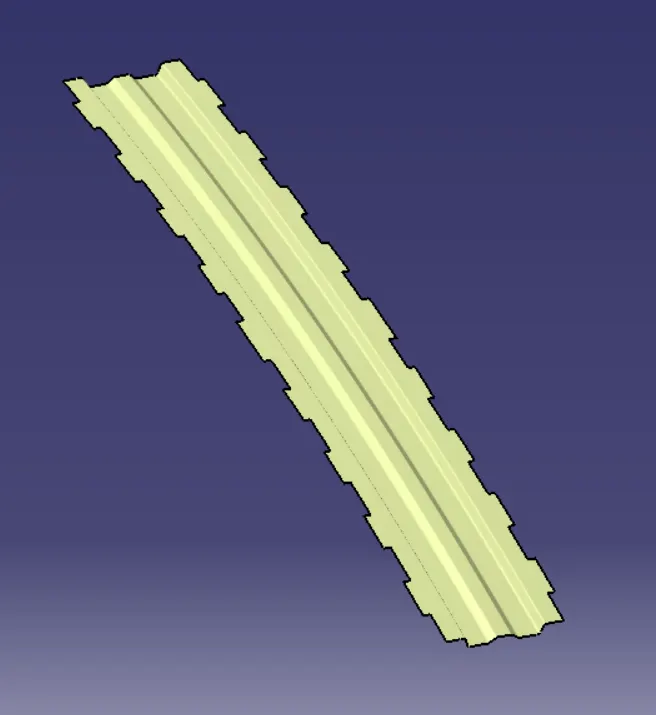
Then I will two more bow roofs. one between the font roof rail and center roof rail and another between the center and rear roof rail.
Bow Roof 1 - The procedure will be the same for creating the bow roofs as it was for the center bow roof. This bow roof will lie between the front roof rail and the center roof rail. so again I will create a point on the edge and one plane through that point parallel to the YZ plane and I will extract the upper surface of the roof and offset it to a certain distance, use the parallel curve the intersect and split to the offset surface.
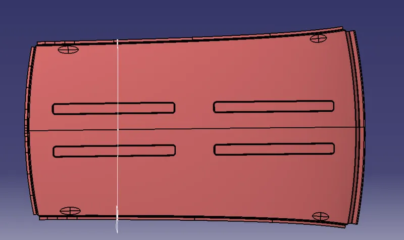
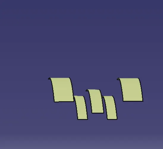
Then I will sweep the edges to connect the surfaces and trim them and join the surfaces. The join is shown below:
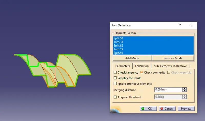
Then I will just provide the fillets and create the mastic regions on the bow roof 1 following the same procedure as I did earlier. Then finally I will mirror the final surface to get complete bow roof 1.
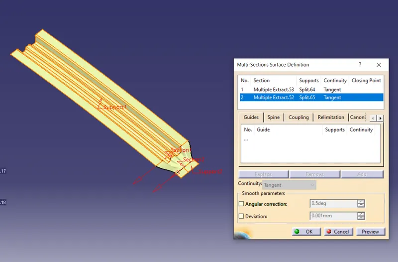
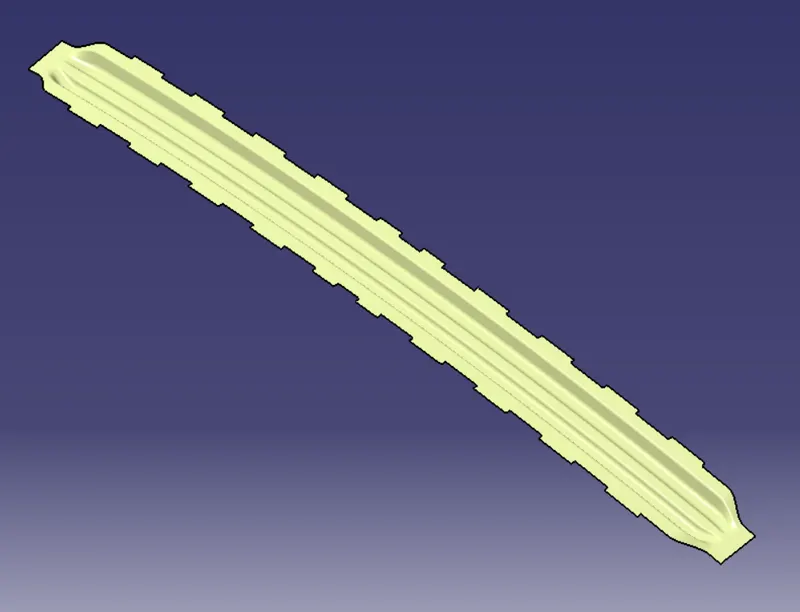
Bow Roof 2 - This bow roof will lie between the center roof rail and rear roof rail. The procedure will be the same as it was for bow roof 1. The intersection and offset surface splits are shown below:
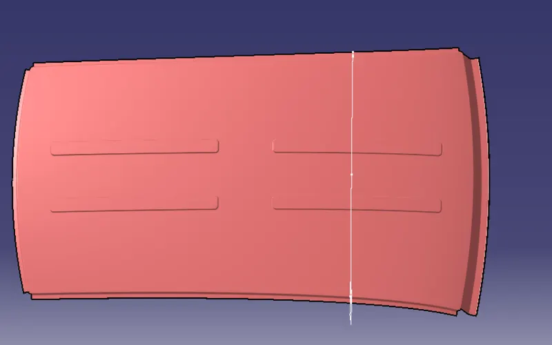
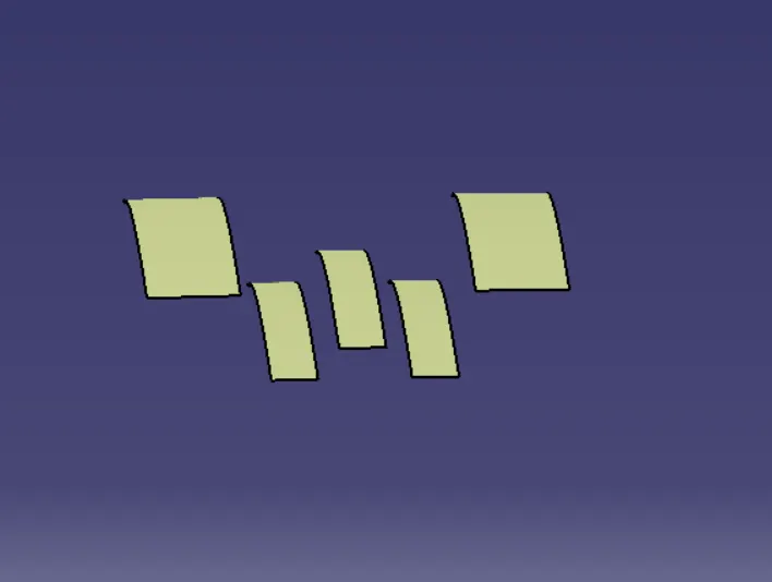
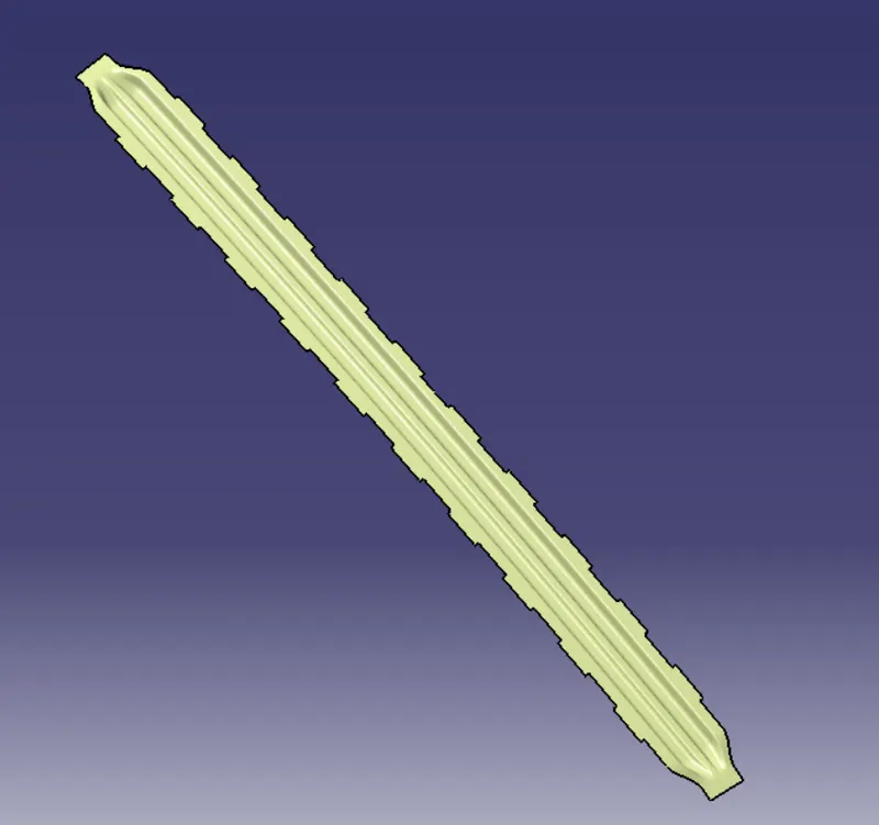
Then I will just sweep, trim and join the surfaces then provide the fillets and use the multisection surface to join it with the extracted flange from the roof and will create regions and finally mirror it to get the complete bow roof 2 surface. The complete bow roof 2 is shown below:
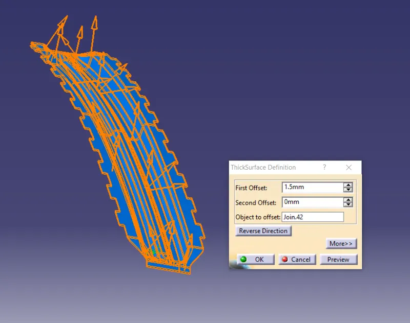
Now I will create the solid bodies of all the roof rails, bow roofs, and the outer roof by thickening them using the thick feature command in part design.
The solid body of the outer roof is shown below:
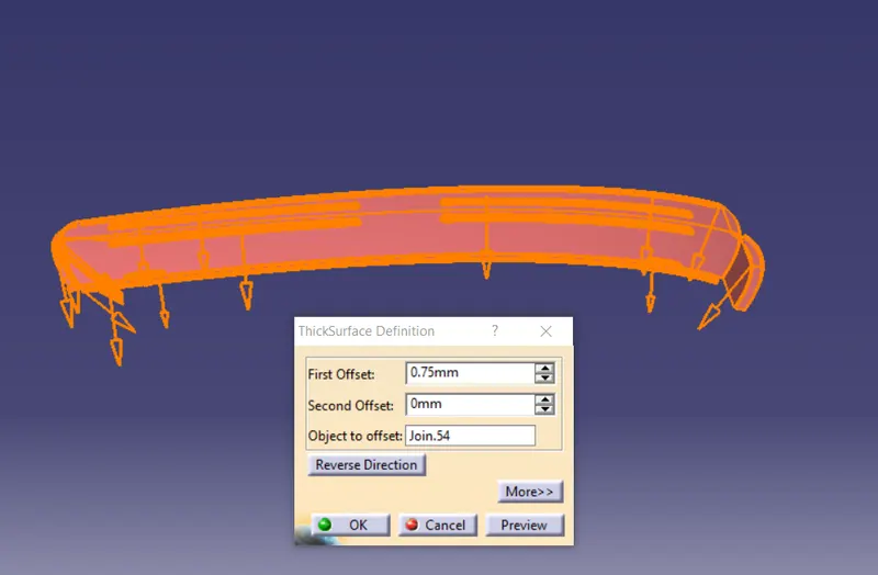
the solid body of the front roof rail is shown below:
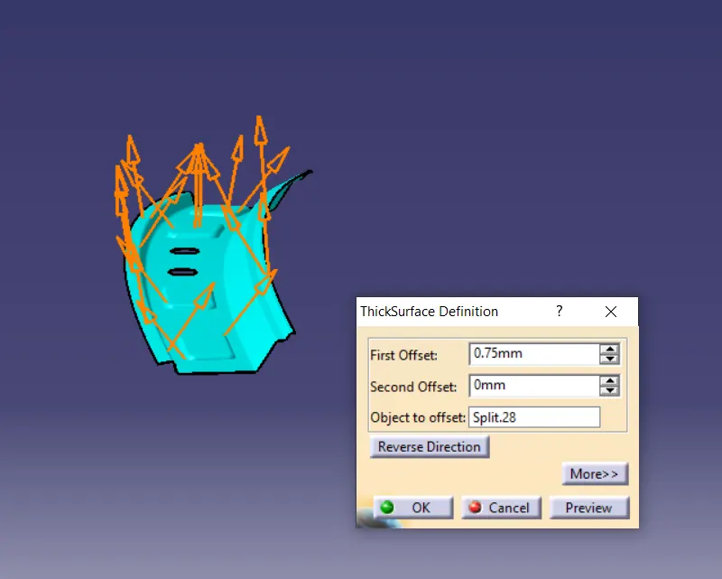
The solid body of the rear roof rail is shown below:
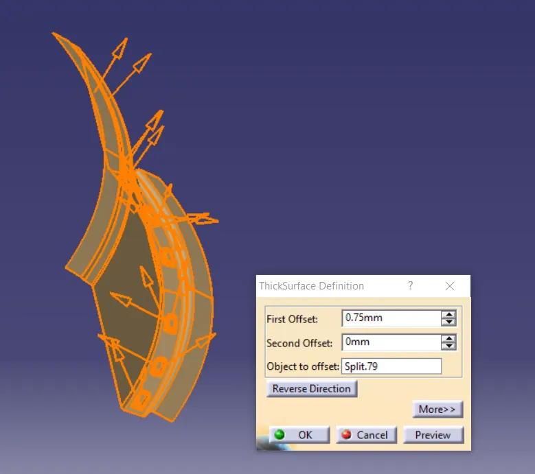
The solid body of the center roof rail is shown below:
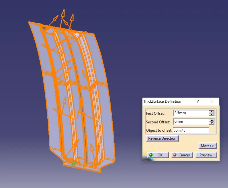
The solid body of the center bow roof is shown below:
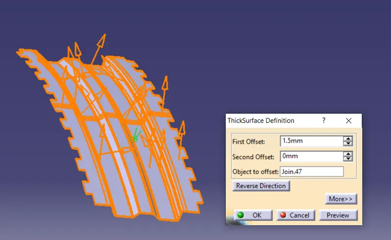
The solid body of the bow roof 1 is shown below:
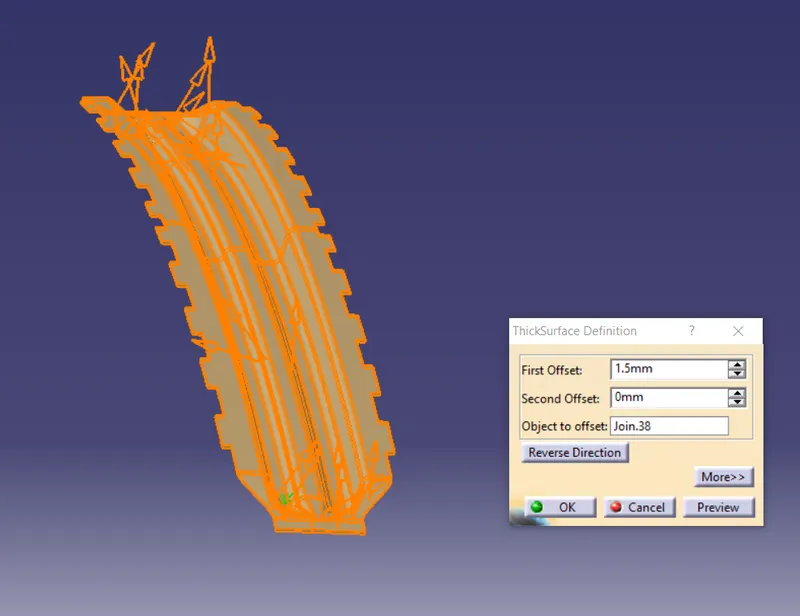
The solid body of bow roof 2 is shown below:
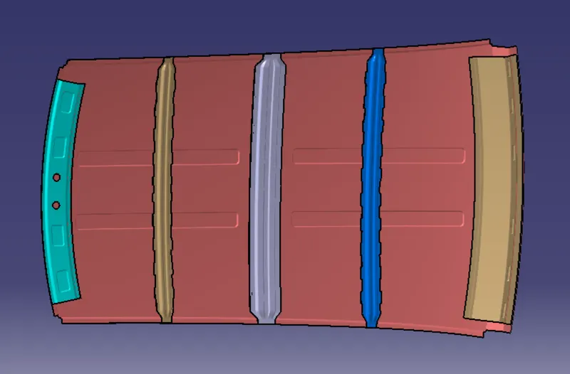
All the roof rails, bow roofs, and outer roof combined in one frame are shown below:
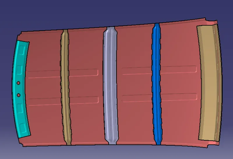
Now after the solid bodies, I will do the analysis of the roof created.
Curvature study - The analysis is done on the roof to validate the position of the bow roofs. so here I will check for the following criteria:
1) Heat distortion
2) snow load
First checking for the heat distortion criteria. Heat distortion study is used to check the ability of the roof to withstand high temperature with respect to the positions of the bow roofs and rails which increases the strength and stability. The prediction formulae for distortion criteria is shown below:
W = [1.73 x 10^(-3) x L] + [1.85 x 10^(-8) x (R^2)/t] + [ 1.10x10^(-3) x l] - 2.68
Judgement Condition : OK< 2.7> 3.1
Where
L = Roof Length in X-Direction[mm](Roof dimension in 0-Y)
R = Roof curvature
R = 2(Rx*Ry)/(Rx+Ry)
Rx = X curvature
Ry = Y curvature
t = Roof plate thickness [mm]
l = Bow Roof Span [mm]
Here for calculating the value of Rx and Ry I will follow the steps mentioned below:
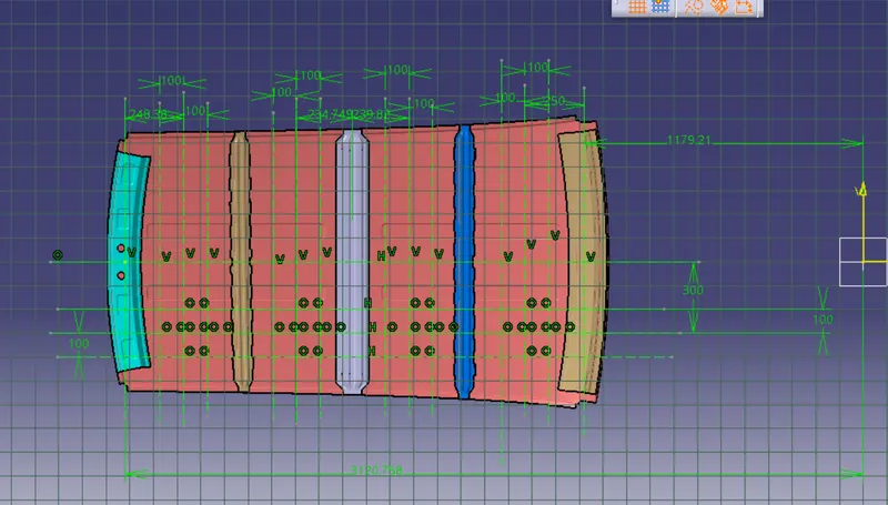
1) I will create one sketch on the plane that will be on the top of the roof and in that sketch, I will draw a 0-y line which will be horizontal.
2) Then I will draw a line horizontal line 300 mm from the 0-y line and again from that 3y line I will create two lines 100 mm apart in both top and bottom direction.
3) I will mark the center between the bow roofs and rails and from that center. I will create the vertical centerline and again create lines 100 mm on both sides of that centerline.
4) then I will create the intersection points and will make all other lines reference geometry.
The sketch is shown below:
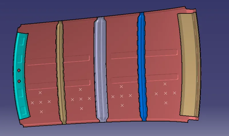
Then I will just project the points on the roof surface. The projection is shown below:
Then I will just create the 3 point circles joining the points in the x and y direction.
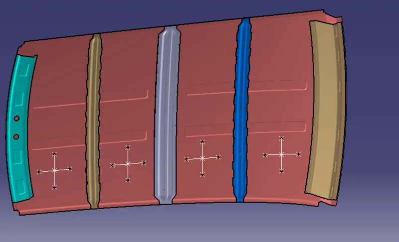
Then I will just simply measure the radius of the circles. The Rx values are shown below:
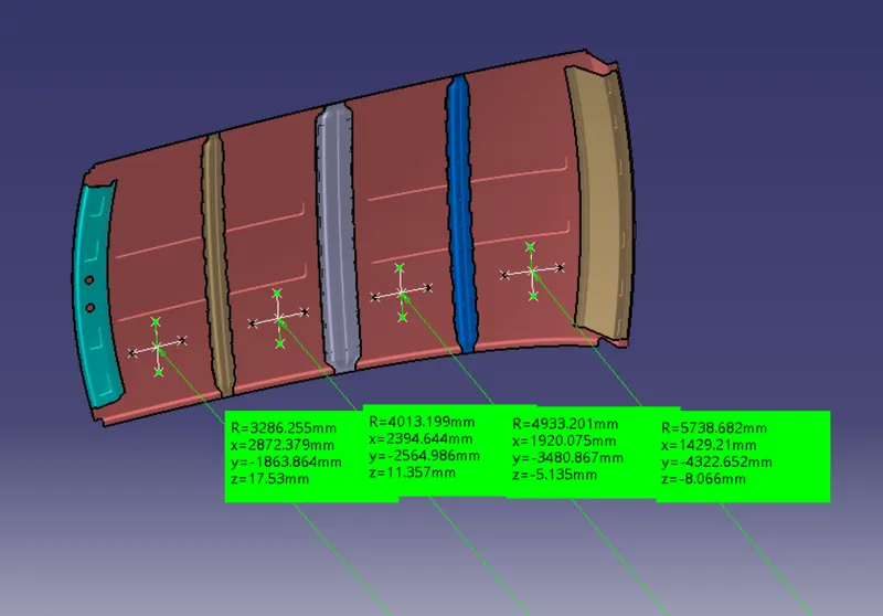
The Ry values are shown below:
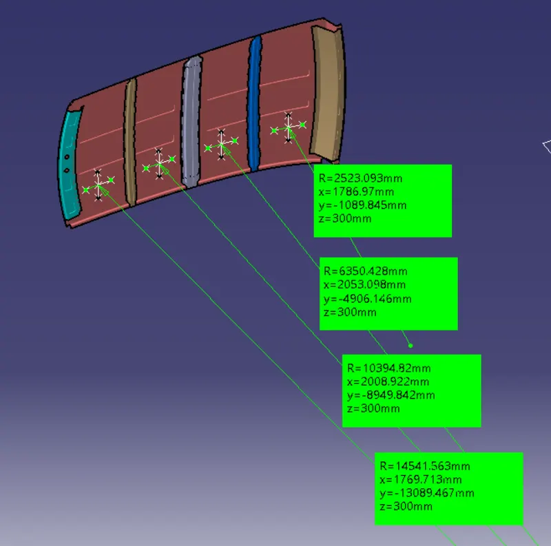
Now I have all the values so now I just put all the values in the formulae to calculate W. THe table is shown below for the calculation:
| S.NO | Roofs | L(mm) | Rx(mm) | Ry(mm) | `R=2*((Rx*Ry)/(Rx + Ry))` | t (mm) | bow span (l) | `R^2/t` | W | OK/NG |
| 1 | Front Roof rail to Bow 1 | 2026.94 | 3286.255 | 14541.563 | 5360.97 | 0.75 | 384.712 | 38319999.12 | 1.957 | OK |
| 2 | Bow 1 to the center roof rail | 2026.94 | 4013.199 | 10394.82 | 5790.73 | 0.75 | 361.72 | 44710071.91 | 2.050 | OK |
| 3 | Center Roof rail to Bow 2 | 2026.94 | 4933.201 | 6350.428 | 5552.81 | 0.75 | 364.905 | 41111598.53 | 1.987 | OK |
| 4 | Bow 2 to Rear roof rail | 2026.94 | 5738.682 | 2523.093 | 3505.11 | 0.75 | 409.014 | 16381061.48 | 1.578 | OK |
Snow load criteria - This study is done to check the ability of the roof to withstand snowfall and bounce back to its original shape without any damage once the load is removed.
The snow load Prediction formula is shown below:
Qr = [Iy x t2] / [α x s x [(Rx + Ry)/2]2 x 10-8]
where
α = My x Lx2 x 10-12 , My = Y(Ly-Y)
Judgement condition = Qr ≥ 3.1
250 ≤ s ≤ 380
t = Roof plate thickness [mm]
Ly = Distance between the front and rear roof Rails on the Vehicle along with 0Y[mm]
Length of Roof panel with the center point between Roof rail Front /Rear as the reference point of the front and the rear.
Lx = Distance between the Left and Right end of the roof on the Roof BOW [mm]
Width of the roof panel exposed on the surface.
Y = Distance front Front Roof Rail to Roof BOW[mm]
s = Distance for which Roof BOW bears divided load [mm]
s = L1/2 + L2/2
Iy = Geometrical moment of inertia of Roof BOW (Y cross-section )[mm4]
Rx = Lateral direction curvature radius of roof panel Y cross-section on Roof BOW [mm]
Roof panel curvature Radius of the Length Lx in Front view
Ry = Longitudinal Direction curvature radius of the Roof panel X cross-section on Roof BOW [mm]
Roof panel X curvature radius of length s in Side view
Again for calculating the Rx and Ry value I will create one sketch on the plane which is at top of the roof surface. so again I will draw an 0-y-axis on the sketch and will draw lines 100 mm apart on both sides and then mark the center between the rails and roofs and from that center, I will draw a vertical centerline and will create lines 100mm apart on both sides of that line. Then I will create intersection points between horizontal and vertical lines. The sketch is shown below:
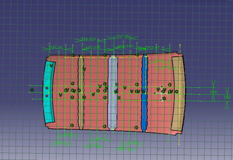
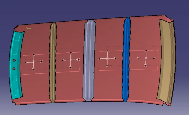
Then I will project the points on the roof surface. The projection is shown below:
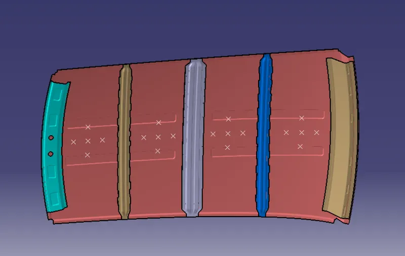
Then again I will create 3 point circles joining points in the x and y-direction
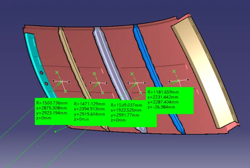
Then I will just measure the radius of the circles. The Rx values are shown below:
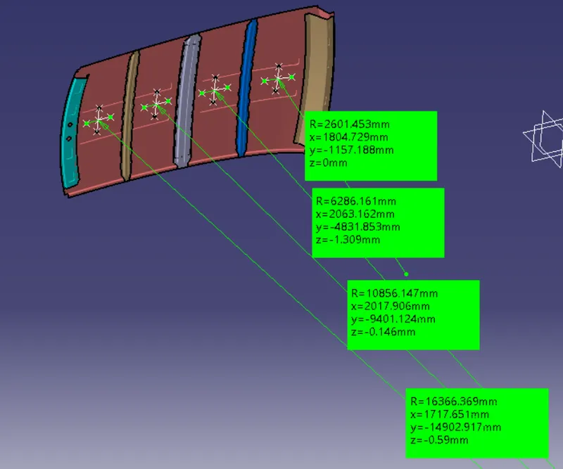
The Ry values are shown below:
Now apart from the Rx and Ry values other values can be easily measured from the model. so I will just put the values and calculate the values of Qr. The table is shown below for the calculation of Qr
| S.NO | Roofs | `ly(mm^4)` | `alpha` | Lx(mm) | Ly(mm) | Y(mm) | `S=(L1+L2)/2(mm)` | Rx(mm) | Ry(mm) | t(mm) | Qr |
| 1 | Front roof rail to Bow 1 | 8187 | 0.814 | 1040.12 | 2026.94 | 490.18 | 373.13 | 1500.736 | 16366.369 | 0.75 | 18.99 |
| Bow 1 to Center roof rail | 33800 | 0.814 | 1055.07 | 2026.94 | 470 | 363.231 | 1471.129 | 10856.147 | 0.75 | 169.26 | |
| 3 | Center roof rail to Bow 2 | 8005 | 0.861 | 1081.17 | 2026.94 | 474.717 | 386.95 | 1539.037 | 6286.161 | 0.75 | 88.29 |
Here I won't be calculating the snow load criteria between Bow roof 2 and rear roof rail because there is no L2 for that.
For the designed to be approved the Qr value should be above 3.1 and in all three cases, I got the values above 3.1.
Section Modulus - Section modulus is a geometric property for a given cross-section used in the design of beams or flexural members. It does not represent anything physically. To define section modulus, it may be defined as the ratio of total moment resisted by the section to the stress in the extreme fiber which is equal to yield stress. There are basically two-section modulus one elastic section modulus and another is a plastic section modulus.
The elastic section modulus is defined as S = I / y, where I is the second moment of inertia and y is the distance from the neutral axis to any given fiber.
S = `I/Y`
I = Moment of inertia
Y = Distance between neutral axis and extreme ends of the object.
So here I will calculate the section modulus for all the roof rails and bow roofs
1) Front roof rail - The section modulus of the front roof rail is calculated below:
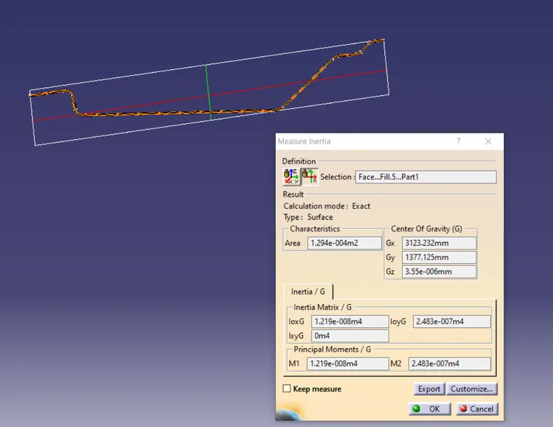
Here u can see that there are two values M1 and M2 so taking the minimum value of the two. and converting the units into mm
I= 12190 `mm^4`
The vertical distance between the two ends is 145.079 mm so the value of Y will be
Y = `145.079/2`= 72.53mm
S = `I/Y=12190/72.53=168.068 mm^3`
2) Bow Roof 1 - The section modulus of bow roof 1 is calculated below:
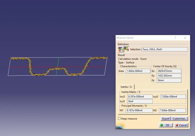
Again taking the minimum value of the two
Moment of inertia (I) = 8187 `mm^4`
The vertical distance between the two ends is 77.669 mm so the value of Y will be
Y = `77.669/2 = 38.83`mm
The section modulus (S) = `I/Y = 8187/38.83 = 210.84 mm^3`
3) Center bow Roof and Center roof rail combined - The section modulus of center roof rail and center bow roof combined is calculated below:
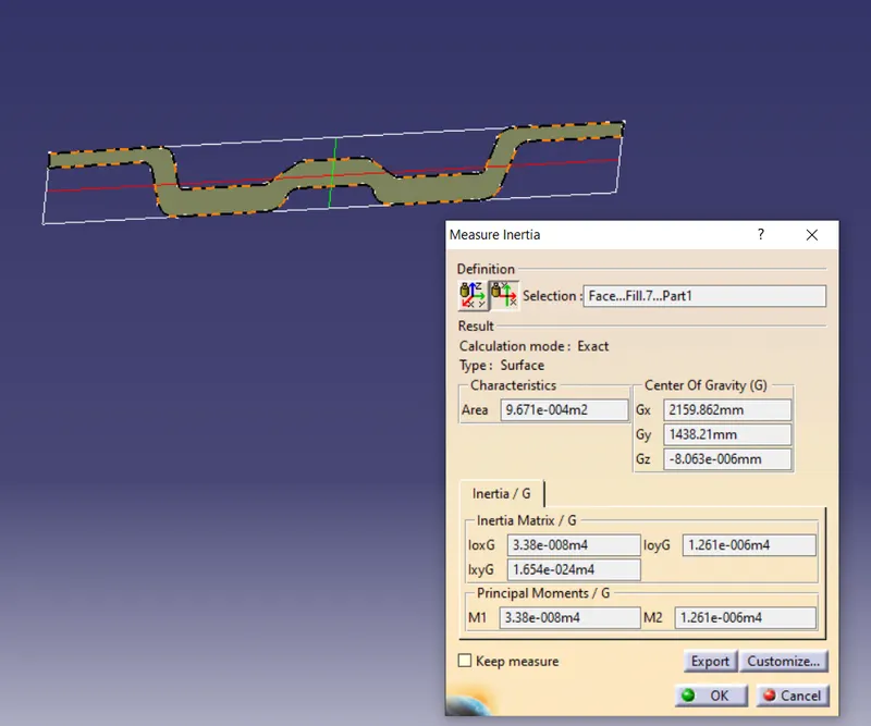
Taking the minimum value of two and converting the unit to mm
Moment of inertia (I) = 33800 `mm^4`
The vertical distance between the two ends is 139.852 mm so the value of Y will be
Y = `139.852/2=69.926 mm`
The section modulus (S) = `I/Y=33800/69.926=483.368 mm^3`
4) Bow Roof 2 - The section modulus of Bow Roof 2 is calculated below:
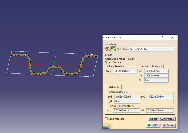
Taking the minimum value of two and converting the unit to mm
Moment of inertia (I) = 8005`mm^4`
The vertical distance between the two ends is 76.126 mm so the value of Y will be
Y = `76.126/2=38.063 mm`
The section modulus (S) = `I/Y=8005/38.063=210.309 mm^3`
5) Rear Roof Rail - The section modulus of the rear roof rail is calculated below:
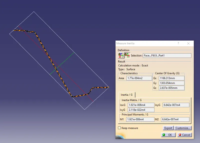
Taking the minimum value of two and converting the unit to mm
Moment of inertia (I) = 19210`mm^4`
The vertical distance between the two ends is 160.137 mm so the value of Y will be
Y = `160.137/2=80.068 mm`
The section modulus (S) = `I/Y=19210/80.068=239.92 mm^3`
Draft Analysis - Draft analysis is a technique to analyze whether the component created is manufacturable or not based on the draft conditions applied. So here I will provide the direction in which the component should be ejected to get the easy removal. My direction will be the tooling axis that I have created.
The minimum draft value for the Automotive plastic component is 3 degrees and for those sheet metal components, 7 degrees of the draft is suitable. The draft is provided to the component for easy removal from the mold in the case of the plastic components.
1) Draft Analysis of Roof (Ditch Area) is shown below:
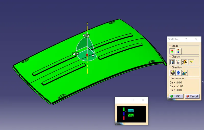
2) The Draft Analysis of the Front roof rail is shown below:
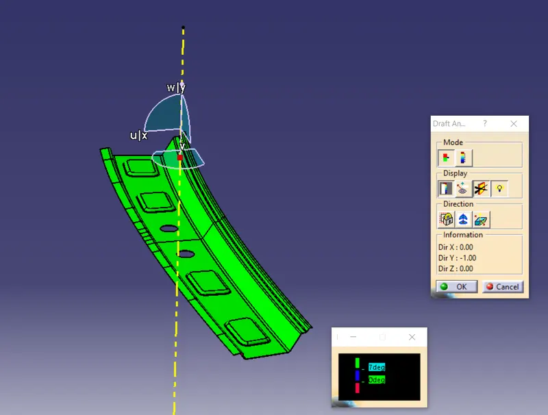
3) The Draft Analysis of Bow roof 1 is shown below:
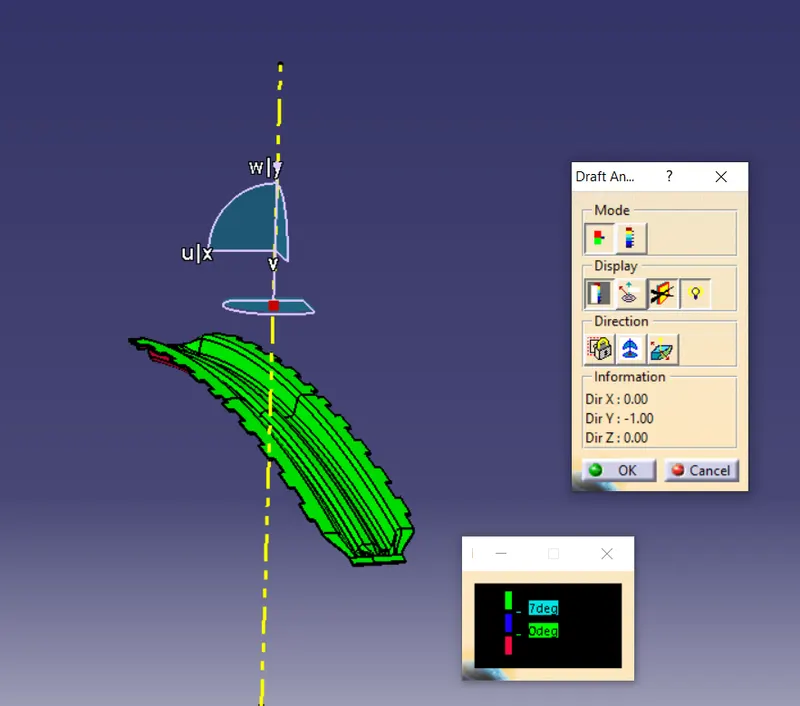
4) The Draft Analysis of the Center bow roof is shown below:
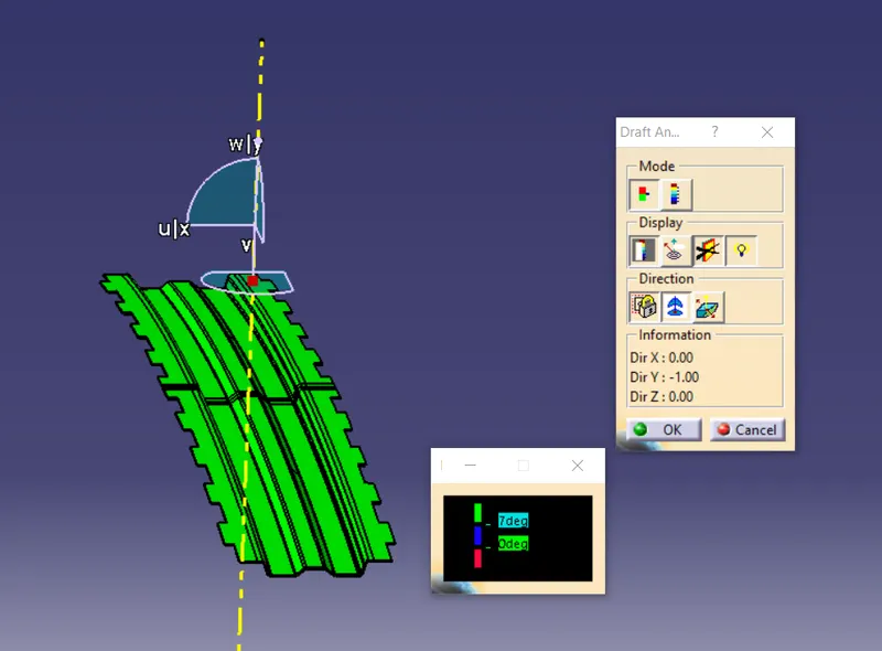
5) The Draft Analysis of the Center Roof rail is shown below:
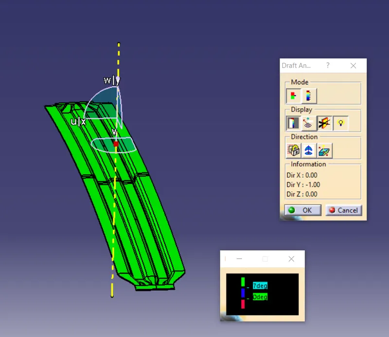
6) The Draft Analysis of Bow Roof 2 is shown below:
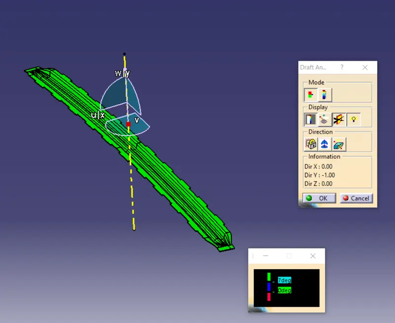
7) The Draft Analysis of the Rear Roof rail is shown below:
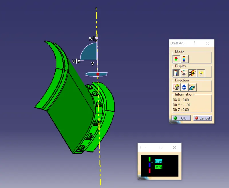
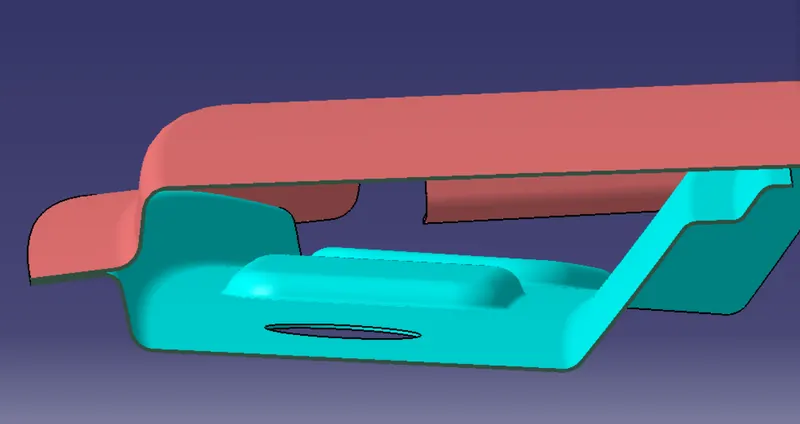
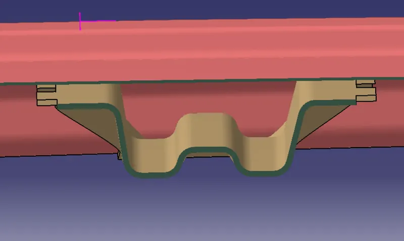
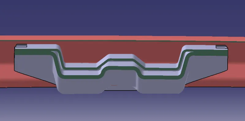
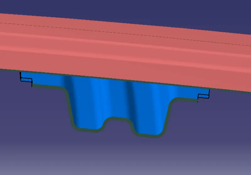
RESULT - The Roof Designing is completed and the section view of the roofs and rails are shown below:
Front Roof rail:
Bow Roof 1:
Center Roof rail and Center bow roof combined:
Bow Roof 2:
Rear Roof rail:
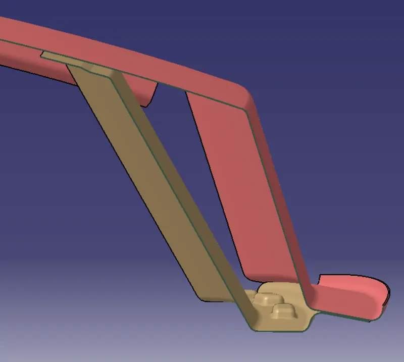
The CAD model of the Roof is shown below:
CONCLUSION - This Concludes the design and Analysis of the Roof using the styling surface given as the input.