Week-4 Challenge WOT Condition Part-2
AIM - To perform the tasks that are given to me using the powertrain blockset.
OBJECTIVES - 1) To write the difference between mapped and dynamic model of engine, motor and generator and to describe how to change the model type.
2) To find out how the model calculate miles per gallon and to state the factors which are considered to model fuel flow.
3) To run the HEV ReferenceApplication with WOT drive cycle and to change the grade and wind velocity in the environment block.
4) To compare the simulated results of hybrid and pure electric powertrains.
PROCEDURES - Powertrain blockset consists of library of automotive components as well as pre assembled engine dynamometer. It can be used to construct complete vehicle model and can be used for fast simulation and real time testing. Powertrain Blockset provides a standard model architecture that can be reused throughout the development process. You can use it for design tradeoff analysis and component sizing, control parameter optimization, and hardware-in-the-loop testing. You can customize models by parameterizing components in a reference application with your own data or by replacing a subsystem with your own model.
For the first part - difference between mapped model and dynamic model
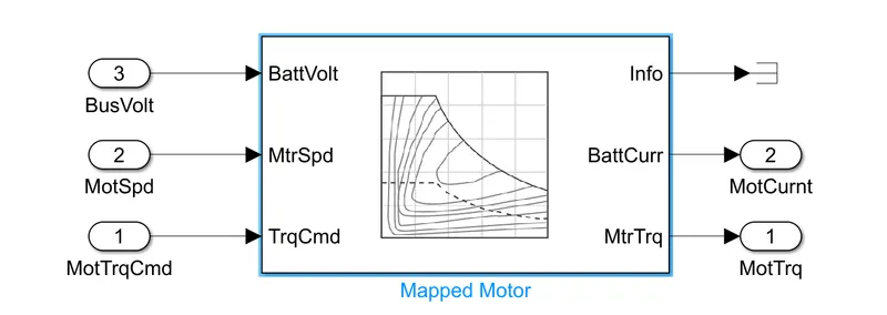
Mapped model - The mapped model is a type of model in which the data points are pre assigned in the lookup tables. The output values are stored for the corresponding input values of motor and generator. The accuracy of this type of model is not that high but the simulation time will be less as it does not run by real time parameters.Mapped engine models are suitable for analysis and design activities that do not require engine subsystem dynamic characteristics, for example, in engine and transmission powertrain matching analysis for fuel economy, emissions, and performance tradeoffs.
The mapped model parameter is shown below of an pure electric vehicle
Dynamic model - Dynamic model is a type of model that uses the combination of output from various subsystems to generate the output. It runs by real time simulation where the required input from the drive cycle is taken and simulation is performed.The accuracy of this model is high because it real time simulation is performed but the time taken to solve the model is very high. Dynamic engine models are suitable for designing control, estimator, and diagnostic algorithms that depend on dynamic subsystem states, for example, in closed-loop AFR control algorithm development.
For changing the model type
here iam considering the hybrid electric vehicle example that is there in powertrain blockset
The default model chosen for say motor was a mapped one which is shown below
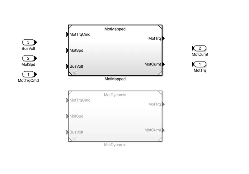
here you can see that motmapped is highlighted which shows that the mapped model is selected and motdynamic is not highlighted.
if i want to change it to dynamic model then i have to right click on simulink workspace and then i have to click on variant,then click on label mode active choice and select dynamic then following sill be shown
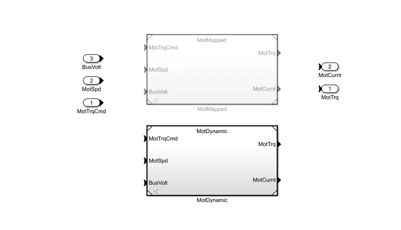
Here now you can see that the motdyanamic which was not highlighted earlier is now highlighted which shows that for the motor dynamic model is used.mapped model is suppressed.
For the second part - Miles per gallon is the fuel economy rating determined by how far a car can travel on a gallon of gasoline or diesel for an engine powered car. In case of electric vehicle miles per gallon will show how far the car can travel on 33.7kWh of electricity which is the energy equivalent of one gallon of gasoline.
The model for the calculation of miles per gallon is shown below
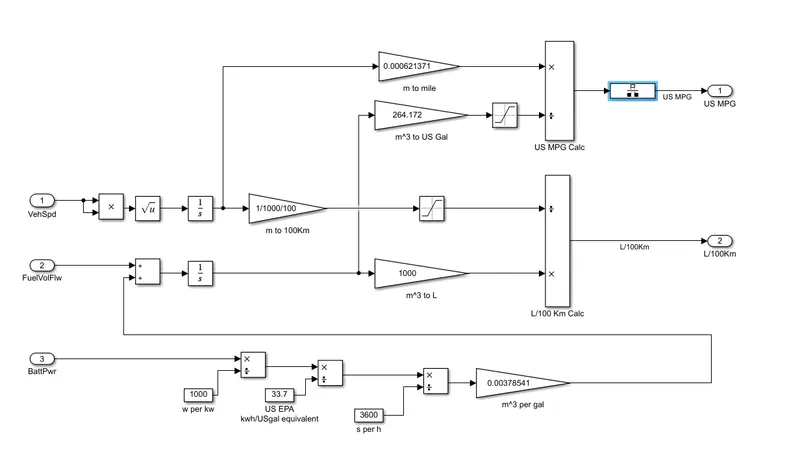
There are 3 factors involved in calculating the fuel economy rating
- vehicle speed
- fuel flow
- battery power
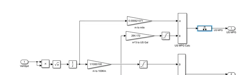
vehicle speed- The vehicle speed is integrated with respect to time which is later converted into km units. Saturation block is used to bound upper and lower limit to obtain the value.Now convert the distance in m into mile using the gain block and then you will have the output. The process is shown below:
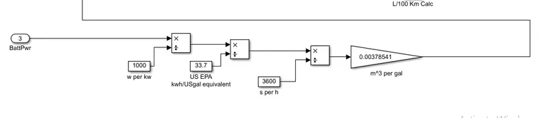
Battery power - The battery power required to propel the vehicle is first converted into kW and battery rating is obtained in terms of KWh. several gain blocks with constant values are used to get the mass flow rate of fuel in kg/m^3. The process is shown below:
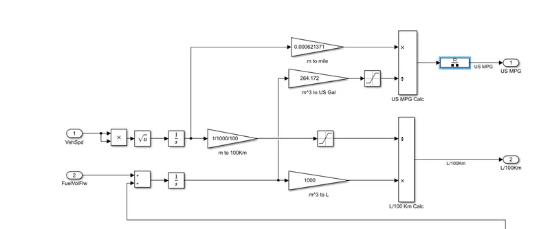
Fuel flow block - The value from the gain block in previous is fed into fuel flow, using this values along with gain blocks the fuel consumption in litres is calculated from vehicle speed and fuel flow, the total amont of fuel to run vehicle for 100 km is obtained(L/100km). Now for calculating Miles per gallon convert the fuel flow value in m^3 into us gal by multiplying 264.172 using the gain block and saturation block to saturate the limits. The process is shwn below:
For the third part - For this purpose i have to run the HEV reference application in powertrain blockset.
The hybrid electric vehicle (HEV) multimode reference application represents a full multimode HEV model with an internal combustion engine, transmission, battery, motor, generator, and associated powertrain control algorithms. we can use the reference application for powertrain matching analysis and component selection, control and diagnostic algorithm design, and hardware-in-the-loop (HIL) testing.
The layout of the car is shown below:
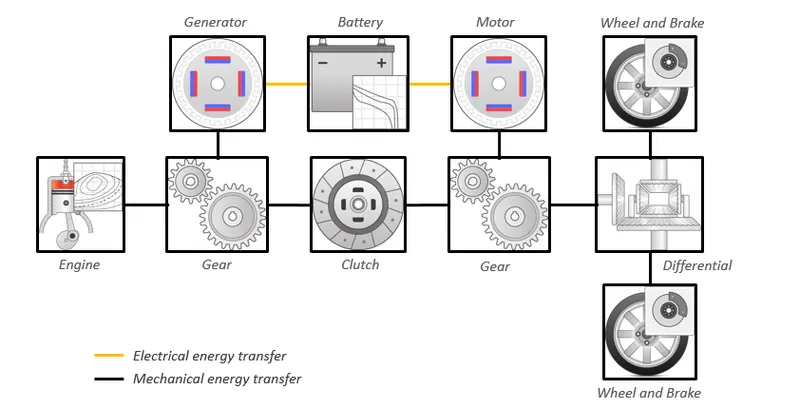
The above shown configuration is a series parallel combination type model in which both engine and battery can individually as well as both together can run the vehicle.
The default hev model from the powertrain blockset is shown below
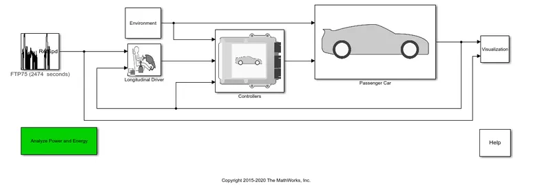
Here as you can see that input is the FTP75 driving cycle but in the condition given to me that is i have to simulate using wide open trottle(WOT) so i will change the input driving cycle to wide open throttle(WOT).
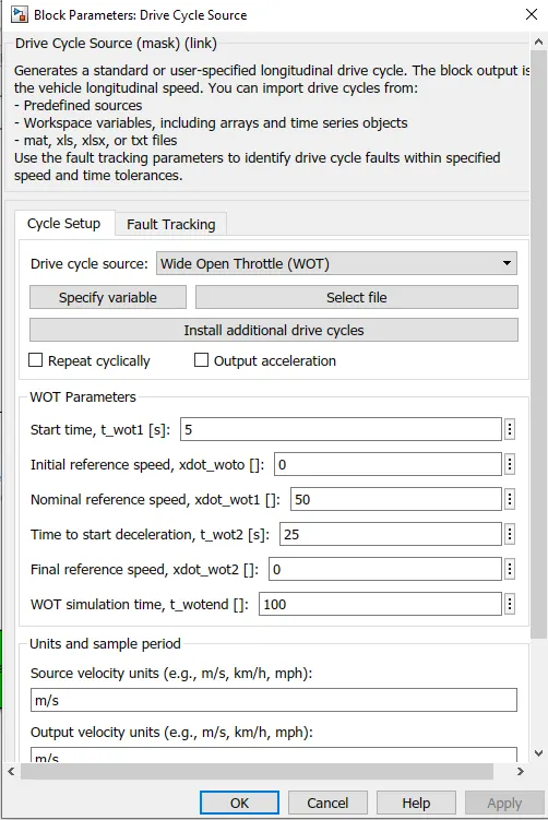
so i will double click on that FTP75 driving cycle block and do the following changes:
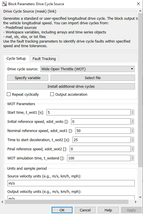
In the above fig. you can see that the start time is 5s,nominal reference speed is 50m/s, and the simulation i have kept here is 100s.
Apart from changing the driving cycle input i have not made any changes in other subsystem and i have also not given any grade or wind velocity.so rest parameters are kept as it is and the simulation is made to run for 100s
The output from the simulation is shown below
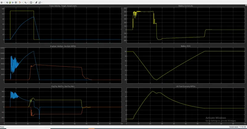
The observations are as follows
- The maximum velocity attained is 88.1mph
- The time taken to achieve max acceleration - 19.948s
- The time taken to decelerate - 4.922s
- Maximum engine speed -5680.58
- Maximum motor speed - 10803.594 rpm
- Maximum motor torque - 300 Nm
- Maximum engine torque- 174.5 Nm
- The maximum current provided by the battery is 523.4 amp.
- The state of battery is discharged from 80% to 68% because the motor will use the battery
- During the regenerative braking the soc is increased again from 68% to 80.12% and the battery is charged.
- The time taken for the charging of battery from 68% to 80.12% is 40s
- Highest mpg is 12.34
Now i will make some changes in the environment block of the model to validate the condition that is given to me.
I will give the wind velocity and grade in the environment block.
The simulink model is shown below.
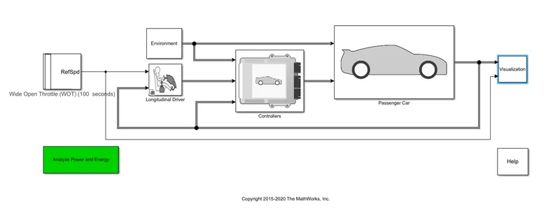
In the above model shown i will double click on the environment block to change its parameters.
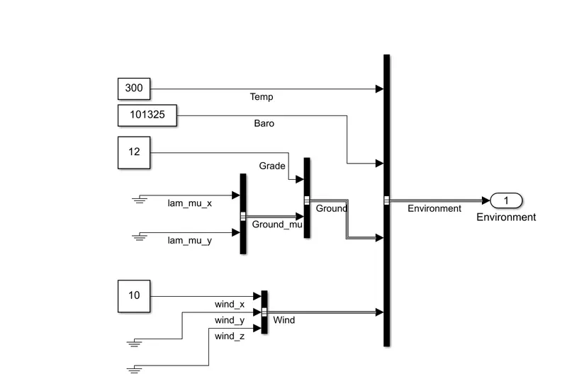
here you can see that i have given the grade value as 12 which was 0 in the previous case and also i given the wind velocity as 10m/s which was aslo 0 in previous case.
I have kept the same driving cycle parameters as it was in previous case. Now i will run the model for 100s and observe the output.
The performance and FE scope is shown below.
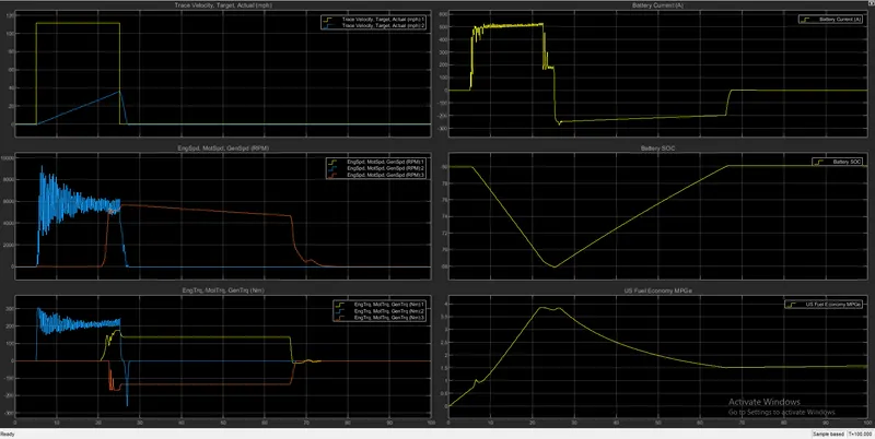
The changes in the output due to grade and wind velocity is:
- The maximum velocity attained is 36.4mph
- The time taken to achieve max acceleration - 19.219s
- The time taken to decelerate - 1.554s
- Maximum engine speed -5694.08 rpm
- Maximum motor speed - 9319.35 rpm
- Maximum motor torque - 307 Nm
- Maximum engine torque- 174.7 Nm
- The maximum current provided by the battery is 531 amp.
- The state of battery is discharged from 80% to 67.87% because the motor will use the battery
- During the regenerative braking the soc is increased again from 67.87% to 80.12% and the battery is charged.
- The time taken for the charging of battery from 67.87% to 80.12% is 41s
- Highest mpg is 3.859
For the fourth part - For this purpose i have to compare the simulated results of hybrid and pure electric powertrains keeping all the parameters same.
For this comparison i will take the same values for hybrid vehicle as i have taken in previous case and i will assign the same values for pure electric vehicle and observe the changes.
First for the hybrid vehicle
Inputs - Driving cycle - wide open throttle and parameters same as previous case
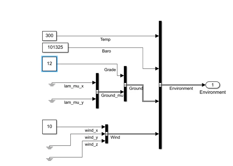
In environment block
Grade - 12
wind velocity - 10m/s
rest parameters will be default and then i will run the model for 100s
The performance and FE scope is shown below
The observations are
- The maximum velocity attained is 36.4mph
- The time taken to achieve max acceleration - 19.219s
- The time taken to decelerate - 1.554s
- Maximum engine speed -5694.08 rpm
- Maximum motor speed - 9319.35 rpm
- Maximum motor torque - 307 Nm
- Maximum engine torque- 174.7 Nm
- The maximum current provided by the battery is 531 amp.
- The state of battery is discharged from 80% to 67.87% because the motor will use the battery
- During the regenerative braking the soc is increased again from 67.87% to 80.12% and the battery is charged.
- The time taken for the charging of battery from 67.87% to 80.12% is 41s
- Highest mpg is 3.859
Now for the electric vehicle
The electric vehicle (EV) reference application represents a full electric vehicle model with a motor-generator, battery, direct-drive transmission, and associated powertrain control algorithms. we can use the electric vehicle reference application for powertrain matching analysis and component selection, control and diagnostic algorithm design, and hardware-in-the-loop (HIL) testing.
The layout of pure electric vehicle is shown below:
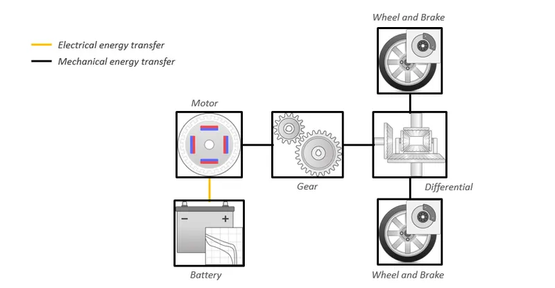
The above shown model is a series type of model in which the battery will give power to the motor which will be transferred to wheels/axle through transmission system.
The simulink model of the pure electric vehicle is shown below:
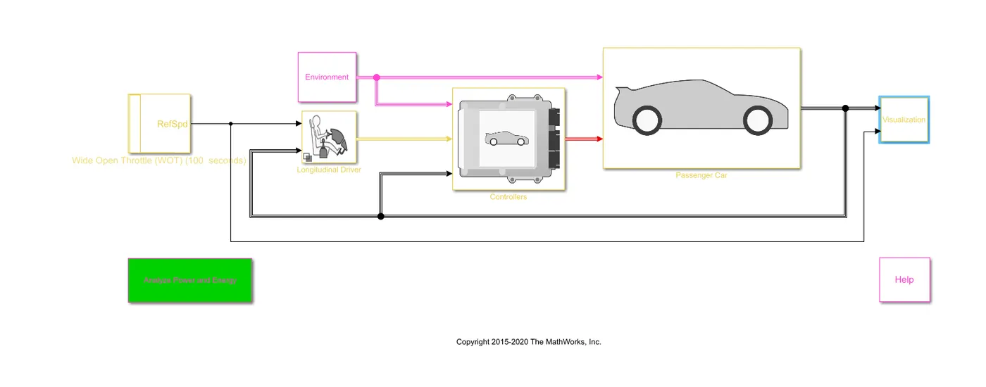
To perform the simulation the inputs will be:
The driving cycle will be wide open throttle and the parameters will be
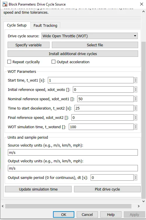
The environment block parameters will be
The grade and wind velocity will be same as that i have used for hybrid vehicle that is shown below:
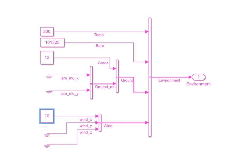
Apart from giving the inputs of driving cycle,grade and wind velocity rest all the parameters will be the default ones and then i will run the model for 100s.
The performance and FE scope is shown below:
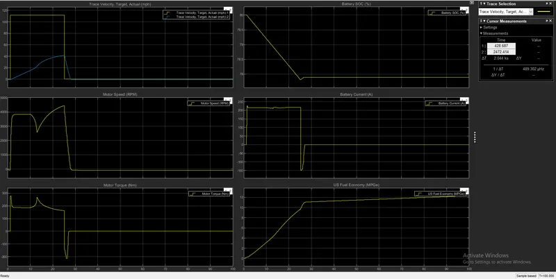
The observations are stated below :
- The maximum velocity attained is 41.51m/s
- The time taken to reach max. acceleration is 24.036s
- The maximum speed of motor is 4452 rpm
- The maximum motor torque is 280 Nm
- The battery is discharged from 80% to 77.81% and time taken to do so is 25.19s
- Highest mpg is 12.29
RESULTS - For the third partThe comparison of WOT drive cycle with default values and changed values is shown in table below
| S.NO | PARAMETERS | (GRADE AND WIND VELOCITY VALUE 0) | CHANGED VALUE(GRADE VALUE AND WIND VELOCITY GIVEN) |
| 1 | maximum velocity | 88.1mph | 36.4mph |
| 2 | time taken to achieve max acceleration | 19.948 s | 19.21 s |
| 3 | Maximum engine speed | 5680.58 rpm | 5694.08 rpm |
| 4 | Maximum motor speed | 10803.59 rpm | 9319.35 rpm |
| 5 | Maximum motor torque | 300 Nm | 307 Nm |
| 6 | Maximum engine torque | 174.5 Nm | 174.7 Nm |
| 7 | Maximum current provided | 523.4 amp | 531 amp |
| 8 | Highest mpg | 12.34 | 3.859 |
Here you can see the affect of wind velocity and grade that is the max velocity that the vehicle was achieving with default condition ( grade and wind velocity 0) was 88.1 mph but due to wind velocity and grade it gor reduced to 36.4 mph. The speeds of motor and engine is also reduced due to same reason.
For the fourth part - The comparison of the result that i got after simulating hybrid and pure electric vehicle power train is shown below in table
| S.NO | PARAMETERS | HYBRID VEHICLE | PURE ELECTRIC VEHICLE |
| 1 | maximum velocity | 36.4mph | 41.51mph |
| 2 | time taken to achieve max acceleration | 19.21 s | 24.036 s |
| 3 | Maximum engine speed | 5694.08 rpm | nil |
| 4 | Maximum motor speed | 9319.35 rpm | 4452 rpm |
| 5 | Maximum motor torque | 307 Nm | 280 Nm |
| 6 | Maximum engine torque | 174.7 Nm | nil |
| 7 | Maximum current provided | 531 amp | 216 amp |
| 8 | Highest mpg | 3.859 | 12.29 |
CONCLUSION - The tasks that are given to me has been completed successfully and the results are plotted and shown in the result section.