Hood design-Week 2
AIM - To Design Hood's outer panel, inner panel, and the necessary reinforcements by following the Master section given considering all the design parameters that go with it to ensure the safety of pedestrians.
INTRODUCTION - The hood or bonnet is the hinged cover over the engine of the motor vehicles. Hoods can open to allow access to the engine compartment or trunk on rear-engine and some mid-engine vehicles for maintenance and repair.
On front-engined cars, the hood may be hinged at either the front or the rear edge, or in earlier models (e.g. the Ford Model T) it may be split into two sections, one each side, each hinged along the centerline. A further variant combines the bonnet and wheel arches into one section and allows the entire front bodywork to tilt forwards around a pivot near the front of the vehicle (e.g., the Triumph herald).
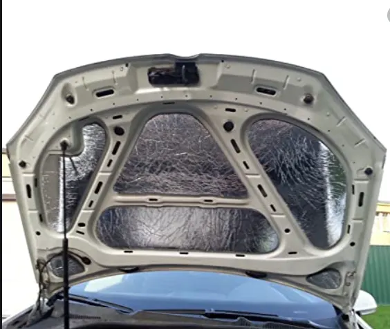
The hood release system is common on most vehicles and usually consists of an interior hood latch handle, hood release cable, and hood latch assembly. The hood latch handle is usually located below the steering wheel, beside the driver's seat, or set into the door frame. On race cars or cars with aftermarket hoods (that do not use the factory latch system) the hood may be held down by hood pins. Some aftermarket hoods that have a latch system are still equipped with hood pins to hold the hood buttoned-down if the latch fails. The hood is generally made up of sheet metal.
The hood consists of the following part:
1) Hood Outer panel - Outer panel is the outermost part of the hood which is visible to us when the hood is in the closed position. The thickness of this part ranges from 0.65 mm to 0.75mm.
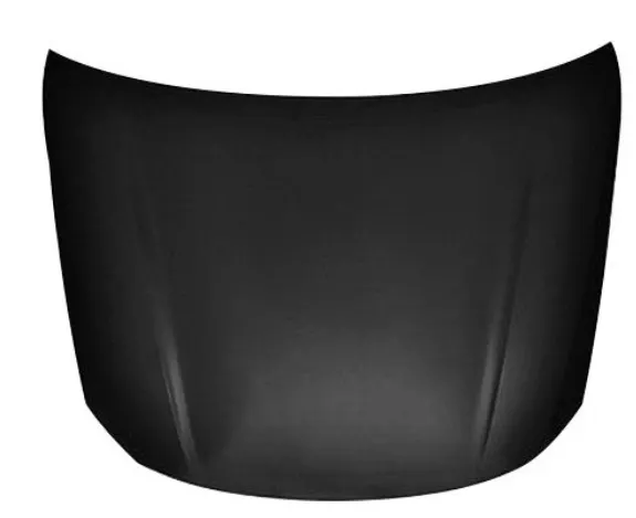
2) Hood Inner panel - Inner panel of the hood includes the main body of the hood. It is the main part of the hood that houses the hinge, latch, and striker reinforcements along with the embosses. The thickness of the inner panel also ranges from 0.65mm to 0.75 mm.
3) Hinge reinforcement - The hood hinge is a mechanism that makes it possible for you to open and close your hood. This part allows the hood panel to move up and down, similar to how a hinge allows the movement of doors and windows. Each car typically has a pair of hood hinges (driver and passenger side) installed in the front of the vehicle. Reinforcement means adding the material to increase the strength so reinforcements are used for supporting the hinges and hinges are assembled on the reinforcement.
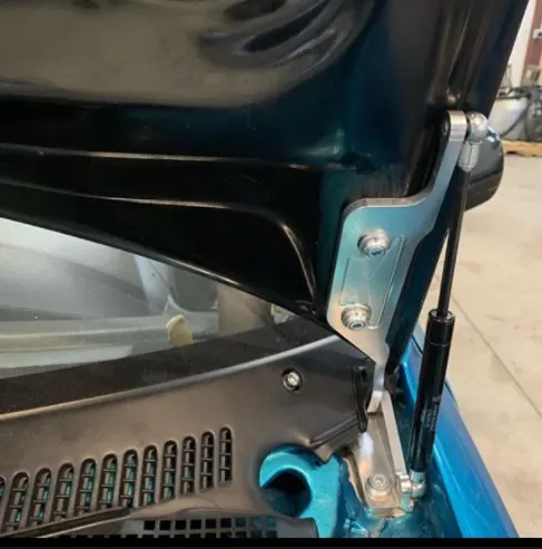
4) Latch and striker reinforcement - A vehicle hood latch and release mechanism is latched when the hood striker engages the latch portion of the mechanism as the hood is moved to its closed position. The mechanism is actuated to release the hood striker by a pushing action on the cable or strand movable in the sheath of a cable assembly rather than by the typical pulling action on current hood releasing mechanisms.
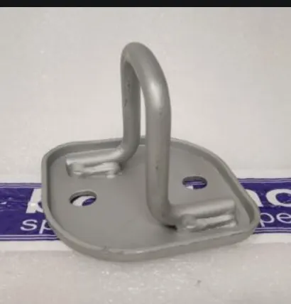
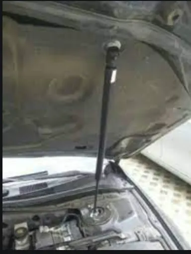
5) Support rod and gas stay - To keep the hood in the open position or to hold it in an open position support rod and gas stays are used. Here the length of the rod is an important factor because that decides the opening angle of the hood. The support rod is attached to the hinges. An example of a hood support rod is shown below:
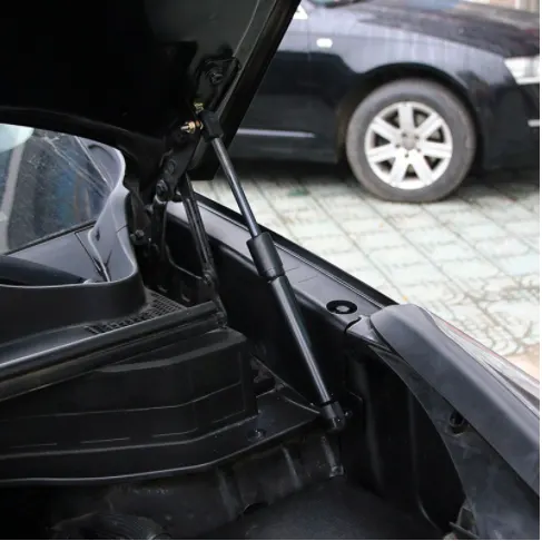
Gas stay is also a type of hood stay but it is automated. It just requires an initial thrust and then the gas itself actuates and works desirably. Gas stay is generally used when the weight of the hood is more so to help the person lifting it as it would be difficult for him to hold it. stud balls are generally used for connecting the gas stay. An example of gas stay is shown below:
The manufacturing process of the hood:
Deep Drawing - Deep drawing is one of the most widely used processes in the sheet metal forming process. Apart from its use in many other sectors, it is applied in the automotive industry for the manufacturing of car body parts.
The deep drawing process is a forming process that occurs under a combination of tensile and compressive conditions. A flat sheet metal blank is formed into a hollow body open on one side or a hollow body is formed into a hollow body with a smaller cross-section.
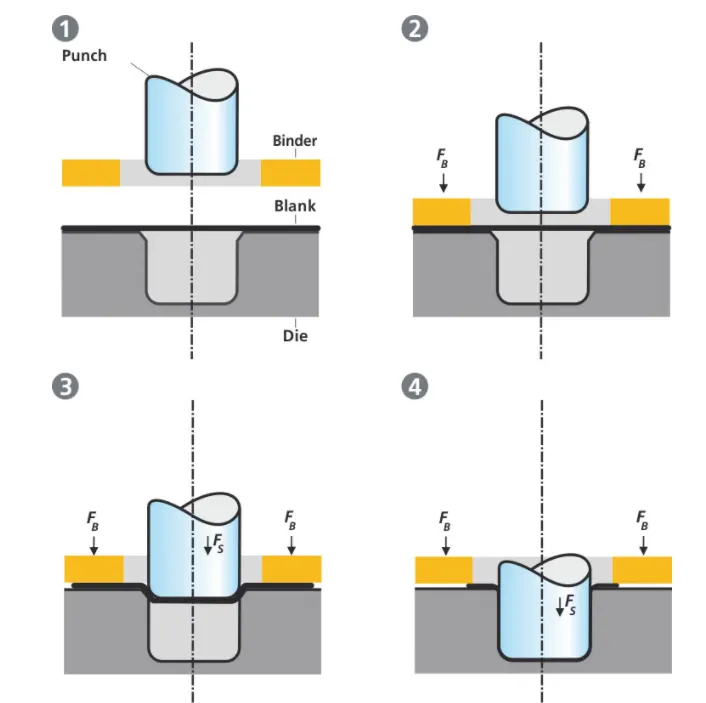
The figure illustrates the deep drawing process. The rigid tools consist of a punch, die, and binder. In a deep drawing, the plate holder closes after the metal sheet blank has been inserted.
Next, the sheet is clamped between the die and the binder. This process slows down the flow of the sheet while it is being drawn and thereby prevents wrinkles from forming under the binder. The punch stretches the sheet over the die radius and forms it in the die. The amount of punch force necessary for forming is thereby continually increased up to the lower dead center of the punch.
Whereas in pure deep drawing there is no reduction of sheet metal thickness, forming is achieved in stretch forming purely as a result of a decrease in sheet metal thickness. Stretch forming is extensively used for the forming of only slightly curved parts with low depth of draw (e.g. roofs, doors).
When drawing complex car body parts in practice, there is usually a combination of stretch and deep drawing involved. It is necessary that the sheet metal is stretched as well as possible without reaching the material’s limits (e.g. splits, wrinkles).
There are approximately 300 to 400 sheet metal parts that fit together to form the body of a car.
DESIGN CONSIDERATIONS - The hood is designed using the EURO NCAP standards which are described below:
EURO NCAP - The EURO NCAP stands for European New Car Assessment Program.
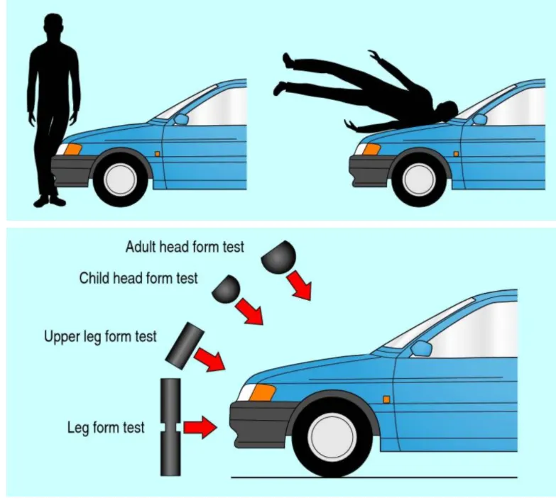
In this, the Adult and Child impact zone is taken into consideration and calculated by plotting the regions from the model data. In the model in this case the outer panel is offset to generate the deformation space in the engine compartment below the styling surface and thereby determining the interference. All these tests are conducted with the help of a dummy that is been hit by a car at 40 km /hr speed.
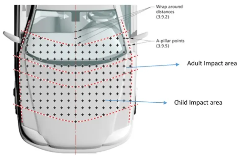
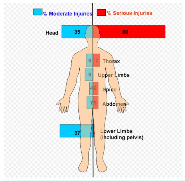
so based on their test the injuries that could happen to pedestrians is shown below:
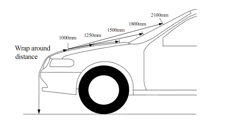
so the design considerations that I have to keep in mind is the wrap-around distance. The head form test area is based on pedestrians wrap around the distance in which the child and adult zone are separated. The test zone covers the full width of the vehicle so that full pedestrian protection can be evaluated throughout the vehicle's front-end structure. once this test is conducted the impact responses are rated in colors that are shown below:
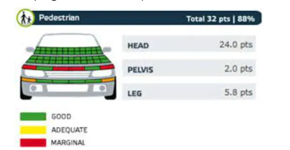
Based on the impact regions thickness of the hood at those regions is reduced to allow softer landing and lower impact. So we have to make sure that those regions should absorb the energy and takes all the deformation so so reduce the impact on the pedestrians. At the same time, the impact of the vehicle should be channeled outside the vehicle to safeguard the occupants from severe injuries. Based on these considerations the inner panel should be embossed with strategized channels and empty cutouts to allow for maximum absorption of such impacts.
PROCEDURE - Here the inputs given to me are :
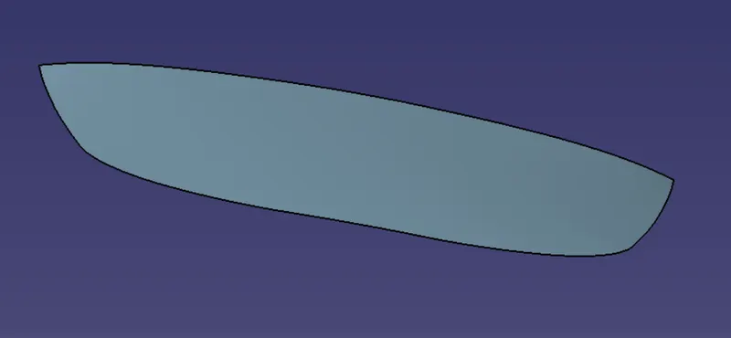
1) Class A surface of the outer panel
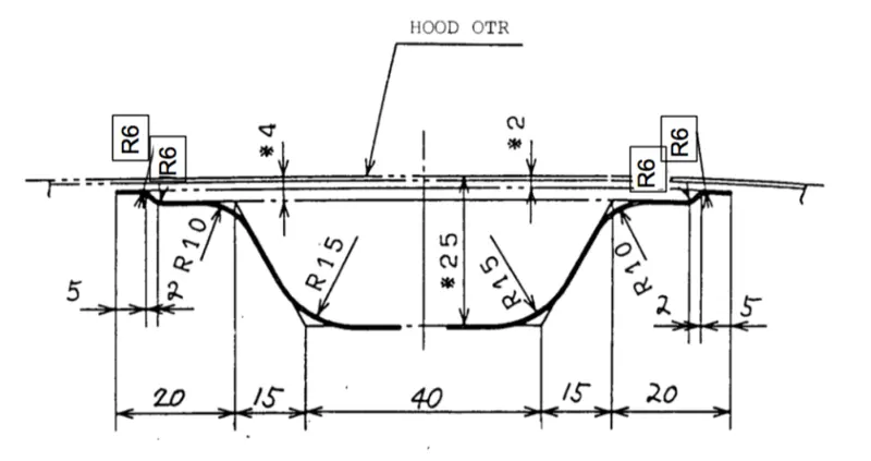
2) Master section
Hood Thickness Information
- Outer Panel Thickness = 0.75mm
- Inner Panel Thickness = 0.75mm
- Reinforcement Thickness = 1.5mm
so from the Class A surface given I will first create the inner panel of the hood using the master sketch. But before that, I have split the class A surface into 2 parts and I have worked on the half portion and later I have mirrored that half portion to get the full hood.
Then according to the master sketch, I have created the first offset which is at a distance of 2mm from the outer panel. The offset is shown below:
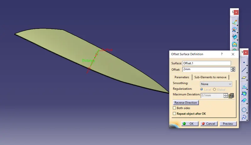
Then I have taken the boundary and used the parallel curve feature to offset it to 20mm.
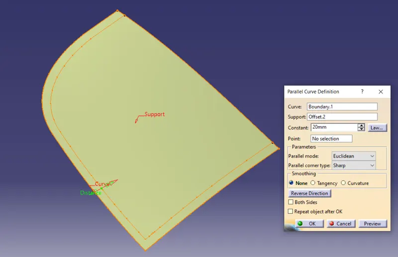
Then I have extruded the parallel curve and provided to the sharp edges and have split it with the offset surface.
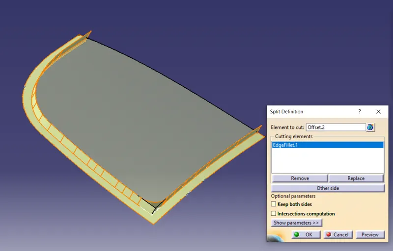
Then I have created the second offset which is at 4mm from the outer panel of the hood. And I have followed the same procedure as I did for the first offset that is To take the boundary, parallel curve according to the master sketch then extrude the parallel curve and split it with the offset.
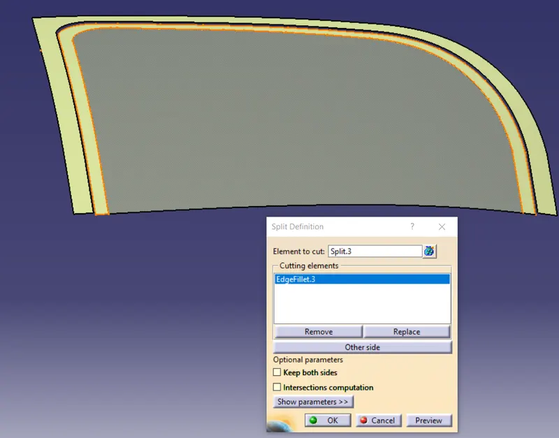
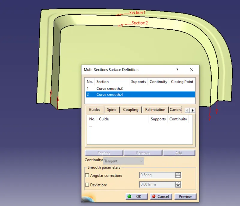
Then I have used the multisection surface to join both the surfaces so for that I have taken the boundary and smooth curved it. The multi-section surface is shown below:
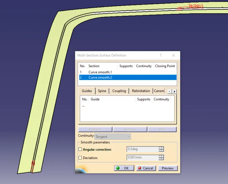
Then I have provided fillets to it. After providing the fillets the surface looks like this:
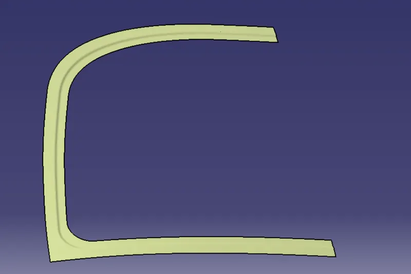
Then again according to the master sketch, I have made the 25 mm offset and followed the same procedure as i have done it before.
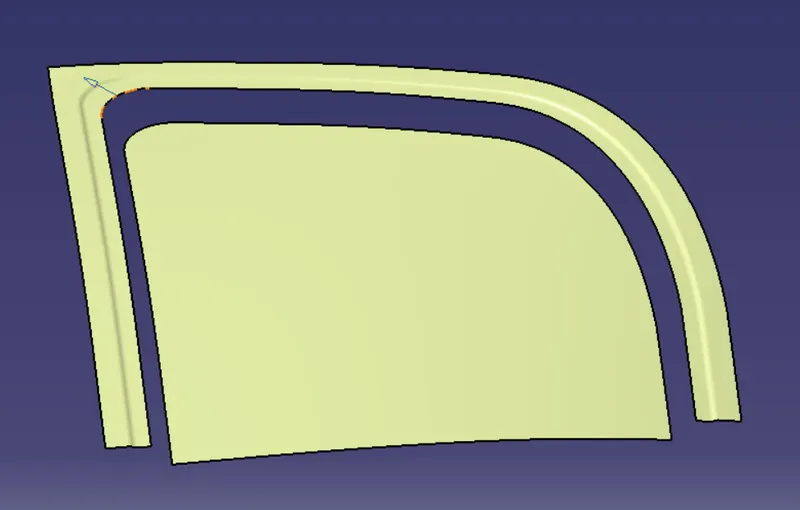
Then i have again used the multisection surface to join the surfaces after taking the boundaries. The multisection surface is shown below:
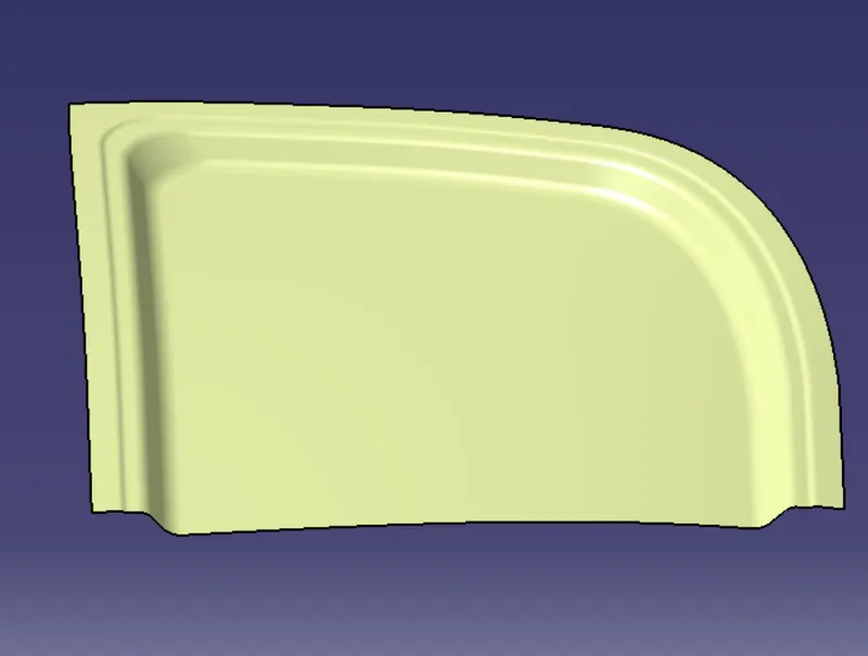
Then I have provided the fillets
Then I have created the emboss on the inner panel
Embosses - Embossing is a metal forming process for producing raised or sunken designs or relief in sheet material by means of matched male and female roller dies, theoretically with no change in metal thickness, or bypassing sheet or a strip of metal between rolls of the desired pattern. The metal sheet is drawn through the male and female roller dies producing a pattern or design on the metal sheet. Depending on the roller dies used, different patterns can be produced on the metal sheet.
Embossing is provided for giving strength and stiffness to the hood and it also helps to distribute the forces and reduce the energy at the time of the collision to ensure the safety of pedestrians. For creating the embossed there is no standard but one thing we have to keep in mind is that the embossed should be provided along Y or V direction.
So to create the embosses I have made the sketch on zx plane and then I have projected them on the inner panel surface. The outcome is shown below:
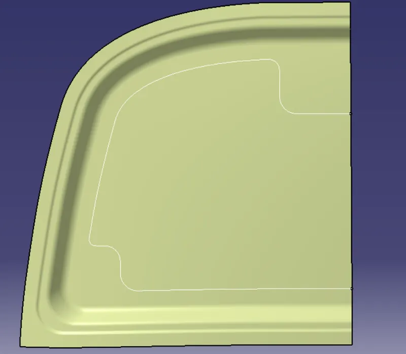
Then I have split it and made the sweep using the along the draft direction. The sweep is shown below:
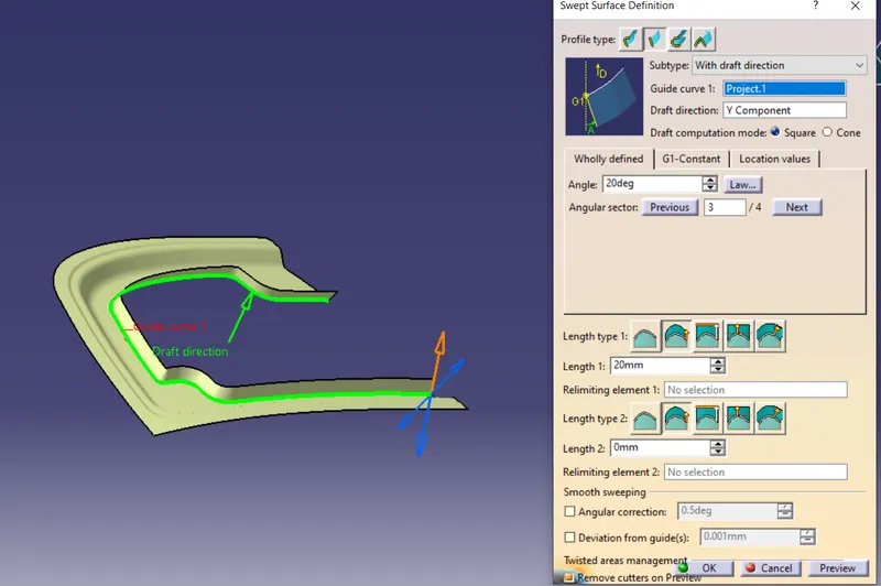
Then i have offset the outer panel surface to a certain and trimmed it with the sweep and provided fillets on it
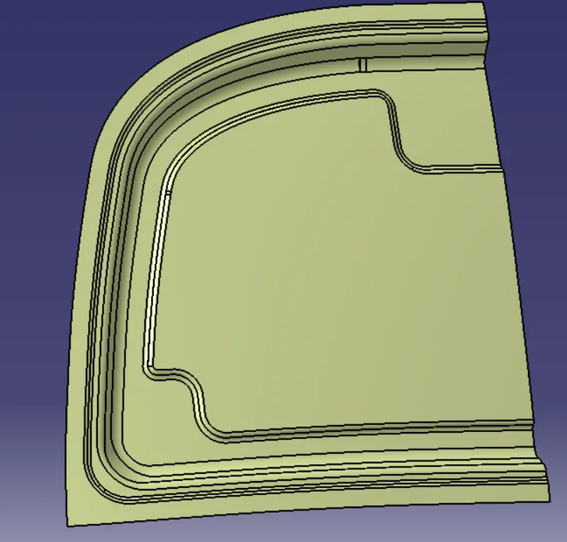
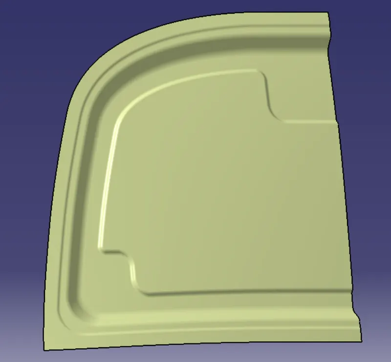
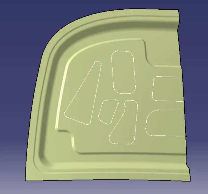
Then I have followed the same procedure to create more embosses on the inner panel. The sketch and the embosses are shown below:
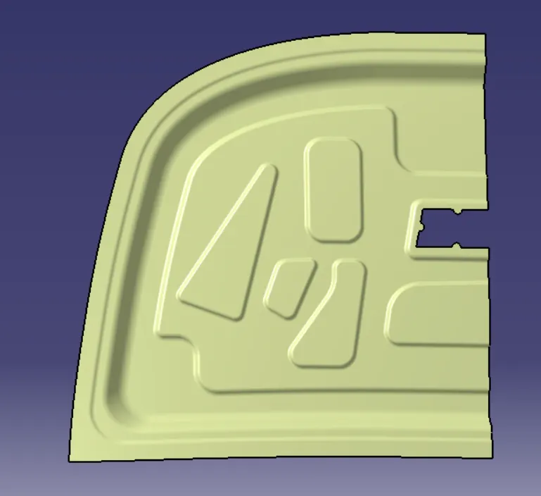
Then I have created the embosses for the hinge and its reinforcement. Reinforcement as mention earlier is provided to support the hinge and increase the strength. Before creating the emboss for the hinge I have created the reinforcement for it so here the hinge is shown below:
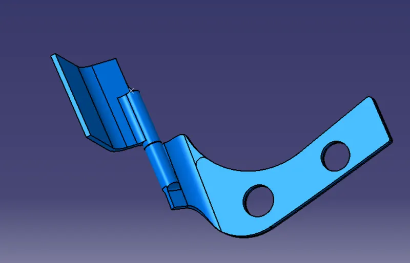
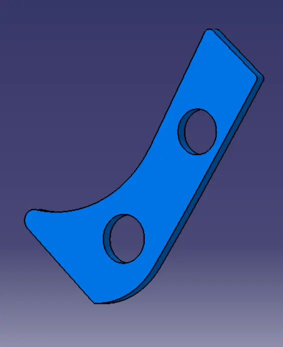
FOr creating the reinforcement I have extracted the back surface of the hinge and made it a solid body The reinforcement is shown below:
Then using the extracted I have made the hinge embosses swept the edges and trimmed them with the inner panel. The hinge emboss is shown below:
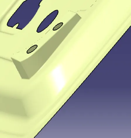
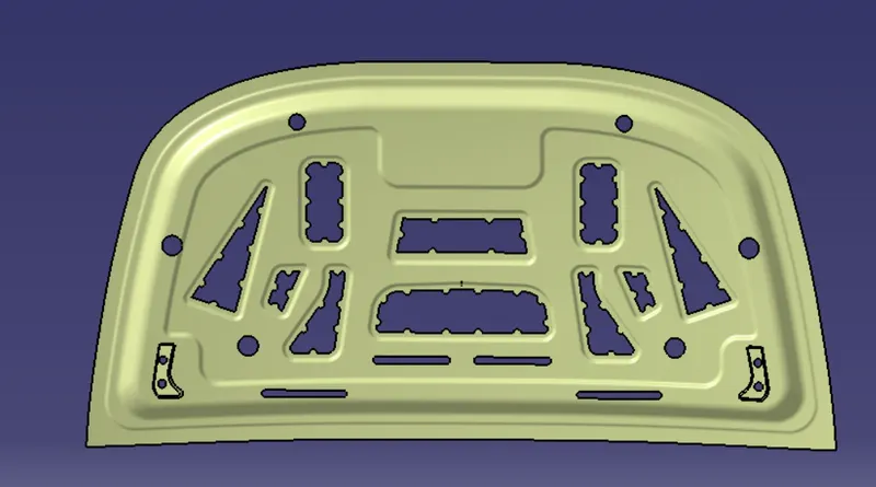
Then I have created some cutouts on the inner panel to reduce the weight to improve the performance and then mirrored it
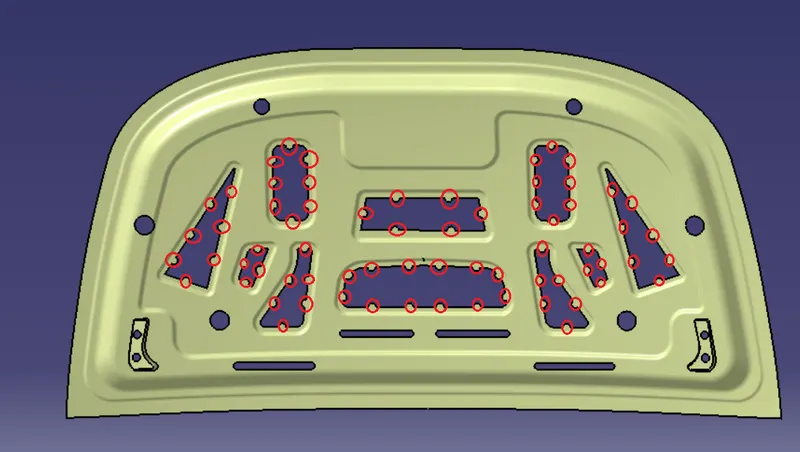
Mastic - Mastic sealants are used to join the inner panel and the outer panel together. They are positioned in such a way that it covers the major part of the hood. They are generally made of hard rubber and are introduced as a paste for joining the inner and outer panels of the hood. They are preferred over spot welding due to the reason they don't affect the styling surface. They increase the strength locally at around 80mm diameter. These sealants can provide thermal and acoustical insulation and may serve as fire barriers and they good electrical properties as well.
So for creating the mastic points I have just created a sketch on zx plane similar to my embosses and created circles on it. Projected it on the inner panel surface and have split it. The mastic points are shown below which are highlighted in the circles
now I have fixed the hinges. The hinges are fixed along the x-direction in a straight line and they are fixed on the reinforcement.
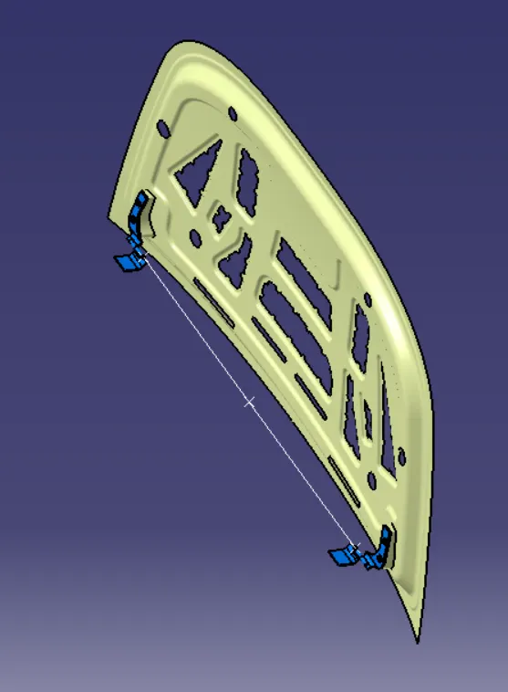
After fixing the hinges I have created one point on the center of the line along the x-direction as u can see in the above fig. I have done that because now I have fixed the latch position according to the point.
The latch is shown below:
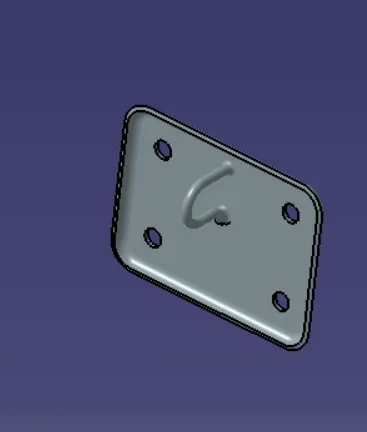
For fixing the latch and striker position I have created one circle from that point along the centerline which is created.
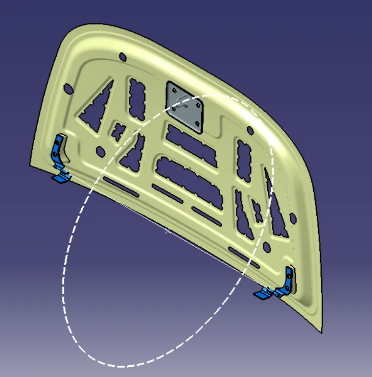
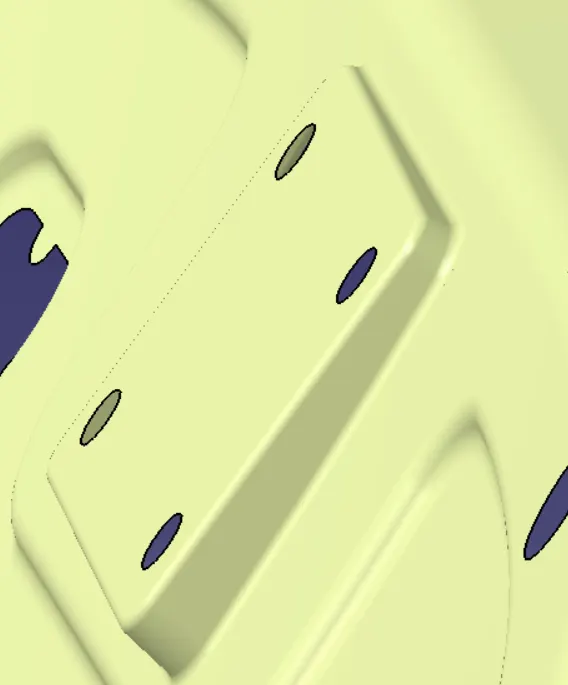
After fixing the position of the latch and striker I have created the emboss of the latch following the same procedure as I did for the hinges. The embossing of the latch is shown below:
Then I have just thickened the final inner panel surface to 0.75 mm The thickened surface along with the hinges and also the trajectory of the striker are shown below:
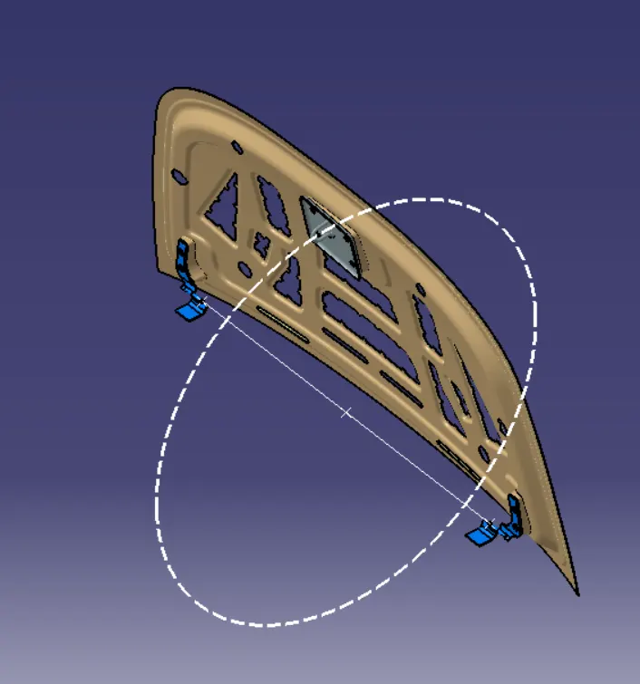
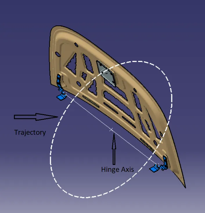
The force distribution due to the embosses created on the inner panel is shown below:
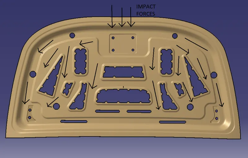
After creating the inner panel I have created the solid body of the outer panel.
so for creating the solid body of the outer panel, I have thickened it by 0.75 mm but before thickening, i have done the hemming of the outer panel. Hemming is generally used to join the inner panel with the outer panel of the hood. Let's see hemming in detail.
Hemming - Hemming is a forming operation in which the edges of the sheet are folded or folded over another part in order to achieve a tight fit. Normally hemming operations are used to connect parts together, to improve the appearance of a part, and to reinforce part edges.
In-car part production, hemming is used in assembly as a secondary operation after deep drawing, trimming, and flanging operations to join two sheet metal parts (outer and inner) together. Typical parts for this type of assembly are hoods, doors, trunk lids, and fenders. The accuracy of the hemming operation is very important since it affects the appearance of the surface and surface quality.
The types of hemming are:
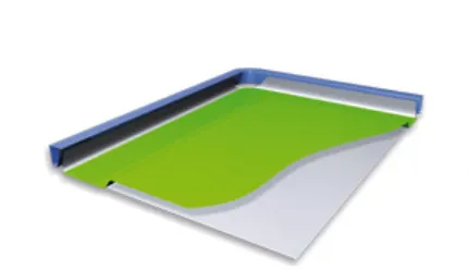
1) Conventional Die Hemming - Conventional die hemming is suitable for mass production. In die hemming, the flange is folded over the entire length with a hemming tool. Normally the actual hemming is a result of a forming operation in which the flange is formed with a hemming tool after the drawing and trimming operations have been completed. The formed flange is then hemmed in several process steps
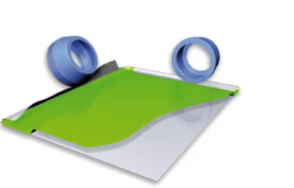
2) Roll Hemming - Roll hemming is carried out incrementally with a hemming roller. An industrial robot guides the hemming roller and forms the flange. Roll hemming is very flexible to use and tool costs are significantly lower as compared to those of conventional die hemming. However, the cycle times are much higher since the hemming is realized using a hemming roller that follows a defined path.
The hemming data given to me is shown below:
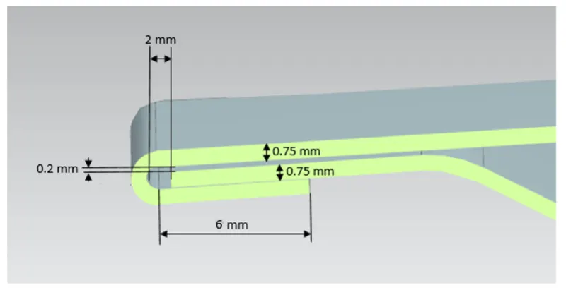
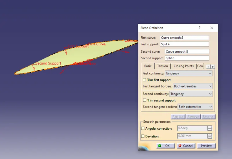
so by calculating the required gap and thickness I have offset the outer panel of the hood and then I have used the blend
feature to connect both the surfaces and later joined both the surfaces and the blend.
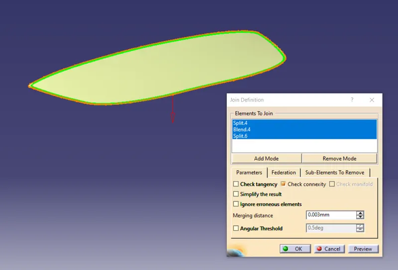
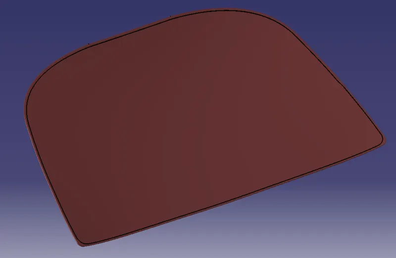
Then I have finally thickened it 0.75 mm to get the solid body of the outer panel. The solid outer panel is shown below:
The hemming is shown below:
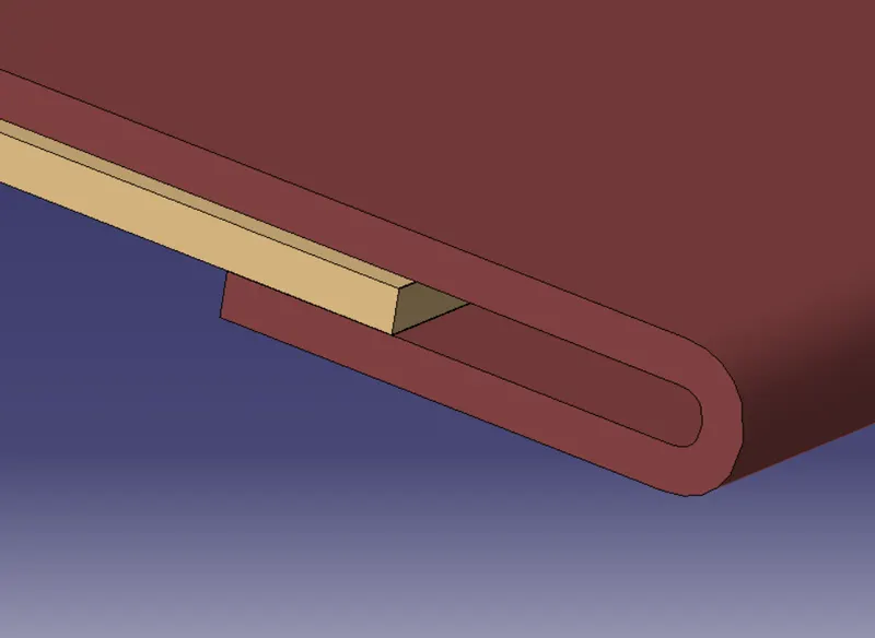
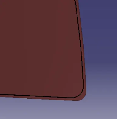
In the hemming process, reliefs are provided to prevent unwanted damages to the surface. So basically these reliefs are provided on the corners to avoid intolerance issues arising from the rolling process. The relief is shown below:
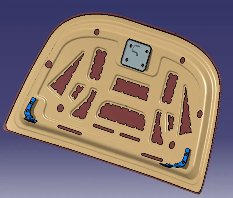
RESULTS - The final design of the hood with the inner panel, outer panel, hinge, and latch reinforcement is shown below:
CONCLUSION - This concludes the design of Hood's outer panel, inner panel, and the necessary reinforcements by following the Master section given considering all the design parameters that go with it to ensure the safety of pedestrians.