Week 8-3D Tetra Meshing Challenge
AIM - To create 3 D tetra mesh on the given models using different tetra mesh methods.
OBJECTIVE - 1) To Create a Teramesh for Housing component with the following quality criteria.
TetraMesh Generation Method: 2D to 3D Conversion
Elements sizes: Min- 2 Units, Target- 5 Units, Max- 7 Units
Tet collapse: 0.15
2) To Create a 3D Tetramesh with the following quality criteria for the given model
TetraMesh Generation Method: Quick Tetra Mesh/ Volume Tetra Mesh
Target Element size: 3 Units.
Tet Collapse: 0.15
3) For the given assembly model, Create a 3D Tetramesh with the following quality criteria.
TetraMesh Generation Method: Quick Tetra Mesh/ Volume Tetra Mesh
Target Element size: 4 Units.
Tet Collapse: 0.15
THEORY - A mesh is a representation of a larger geometric domain by smaller discrete cells. Meshes are commonly used to compute solutions of partial differential equations and render computer graphics and analyze geographical and cartographic data. A mesh partitions space into elements (or cells or zones) over which the equations can be solved, which then approximates the solution over the larger domain. Element boundaries may be constrained to lie on internal or external boundaries within a model. Higher-quality (better-shaped) elements have better numerical properties, where what constitutes a "better" element depends on the general governing equations and the particular solution to the model instance.
Tetra Mesh - It is a type of 3 D mesh that has 4 vertices, 6 edges, and is bounded by 4 triangular faces. These elements are used where the geometry has high thickness and complexity. 3 D elements are usually used to mesh volumes. They are derived from 2 D elements that are used when the model is having a thickness of more than 6 mm. 3 D solid elements only account for translational displacement. An example of a tetrahedron element is shown below:
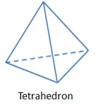
Important quality criteria to check for tetra elements are:
1) Tet collapse - Tet collapse is one of the quality parameters, which will be checked while generating tetrahedral elements. It can be calculated by measuring the distance of a node from the opposite face, then each of the four values will be divided by the square root of the opposite faces' area. The minimum of four resulting values is then normalized by dividing it by 1.24.
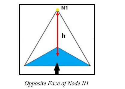
2) volumetric skew - The skewness measured in solid elements is the volumetric skew. And as we know skewness is the quality of elements in terms of angle.
3) jacobian - The deviation of the element from the ideal shape is measured through jacobian. The ideal value of jacobian is 1.
4) warpage - This is the amount by which an element (or in the case of solid elements, an element face) deviates from being planar. since three points define a plane, this check only applies to quads. The quad is divided into two trias along its diagonal, and the angle between the trias normals is measured.
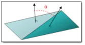
5) Aspect ratio - The aspect ratio is the ratio of maximum length to the minimum length. when you see a quad element one side smaller than the remaining three sides then the element will fail for aspect ratio.

PROCEDURE -1) Here three models are given to me and for all three models I have to generate the 3 D tetra mesh according to the methods specified. so taking the first model which is the housing model. First I have to import the model. The housing model after importing is shown below:
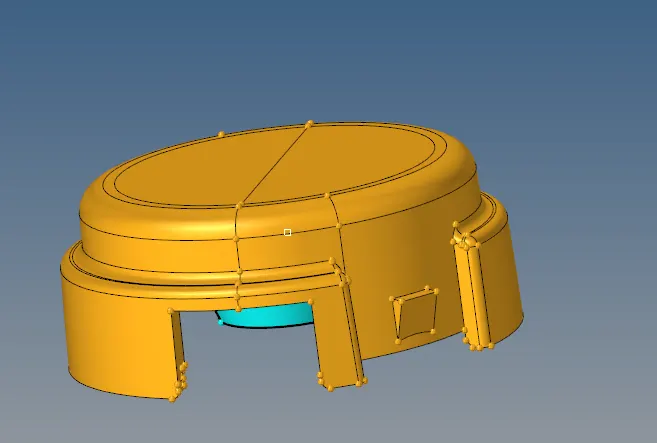
For this model, I have to use the conversion method for generating the 3 D tetra mesh so I will mesh delete the solid if there is any, then I will simply mesh the surfaces only with trias and later convert that 2 d shell element into 3 D tetrahedron elements.
The 2D mesh for the model is shown below:
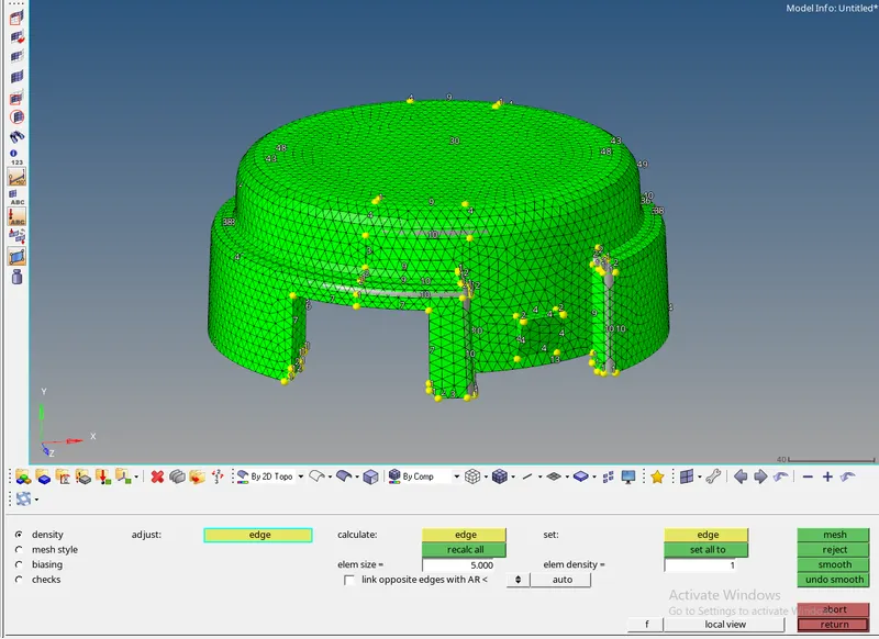
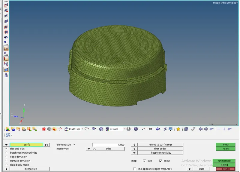
Now the 2 D shell elements are created and I will select the tetra mesh option under the 3 D section in hypermesh to create the 3 D elements.
Under the tetra mesh, I will select all the 2 D shell elements and click on the mesh. The tetra mesh for the model is shown below:
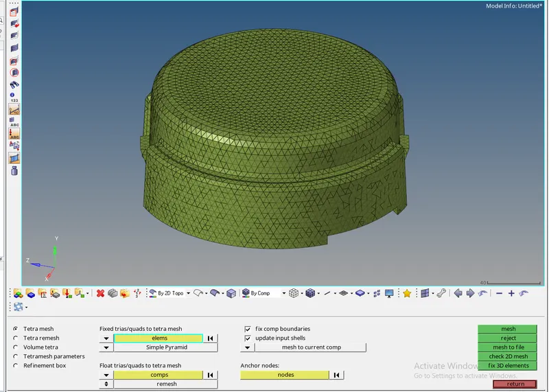
For seeing the tetrahedron elements I will mask a few elements.
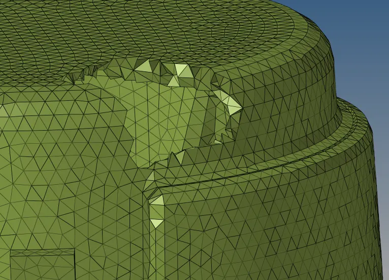
now I will check the quality of the elements. so here I will just check the tet collapse. For checking, I will go to tools and then check elements, select the 3 D option and see the tet collapse. The tet collapse acceptable is 0.15 as per the quality given. so on checking, I found out that 241 elements failed for tet collapse. so to clear the element failures for tet collapse I can use two methods:
1) we can use the translate command to increase the height and clear that failure.
2) we can remesh failed tetra elements under the tetra mesh section.
But for remeshing I have to set the tetra mesh parameters. The tetramesh mesh parameters are shown below:
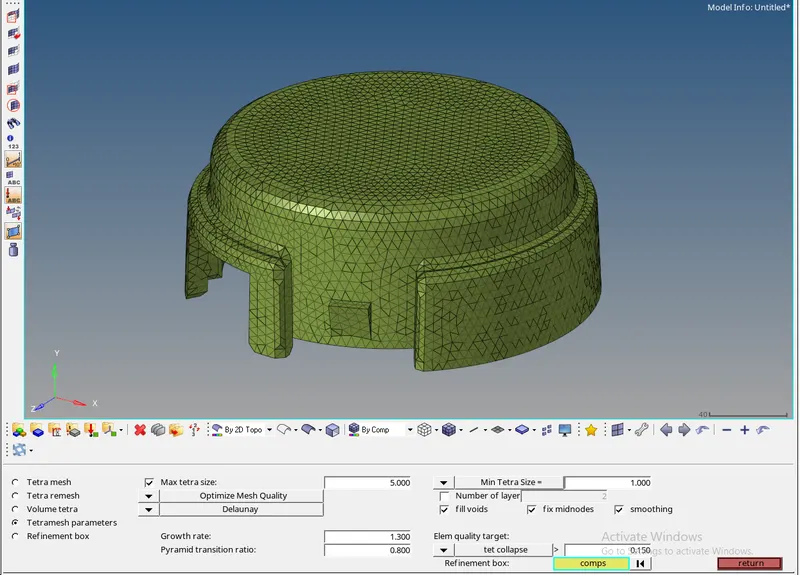
Now I will simply just remesh using the parameters shown above and will select both the 3 D elements and 2 D shell elements for remeshing. After generating the 3 D tetra mesh it is very important to delete the 2 D shell elements.
The final 3 D mesh of the model is shown below:
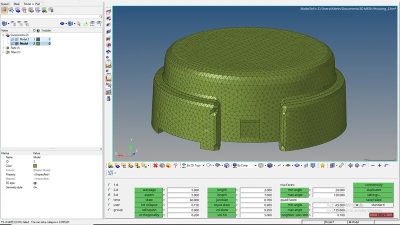
Here we can see that 15 elements failed for tet collapse but the percentage failure, when compared to the total number of elements, is 0.0 % so it is acceptable.
Now one more component is there along with the housing for that also I have to generate the tetra mesh. so after deleting the solid the component is shown below:
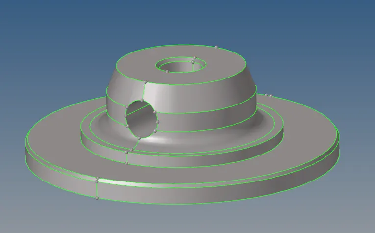
Now I will follow a similar procedure as I did for the previous component is first I will create a 2 D mesh using trias only. The 2 D mesh is shown below:
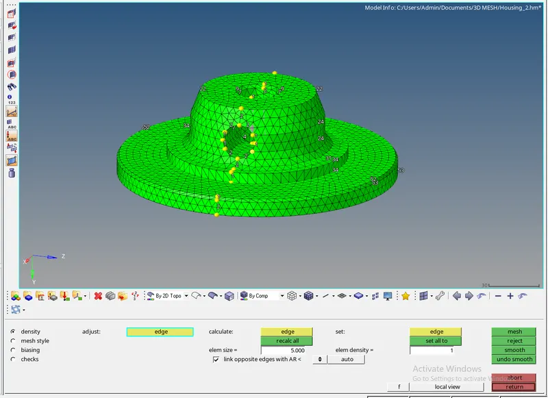
Now again I will convert the 2 D mesh to 3 D mesh using the tetra mesh option under the 3 D section. The 3 D mesh of the component is shown below:
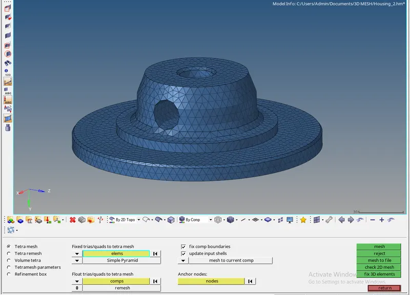
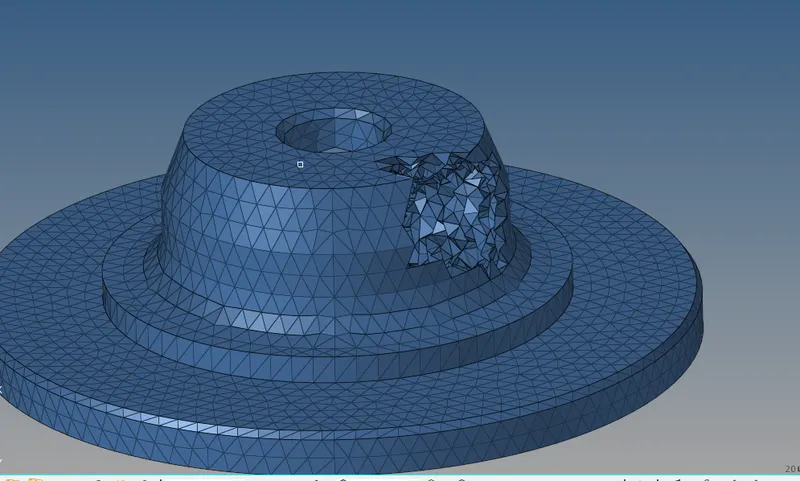
Now again I will remesh the tetra elements to clear the tet collapse failures but before that, I have to set the tetra mesh parameters. The parameters are shown below:

The final 3 D tetra mesh of the component is shown below:
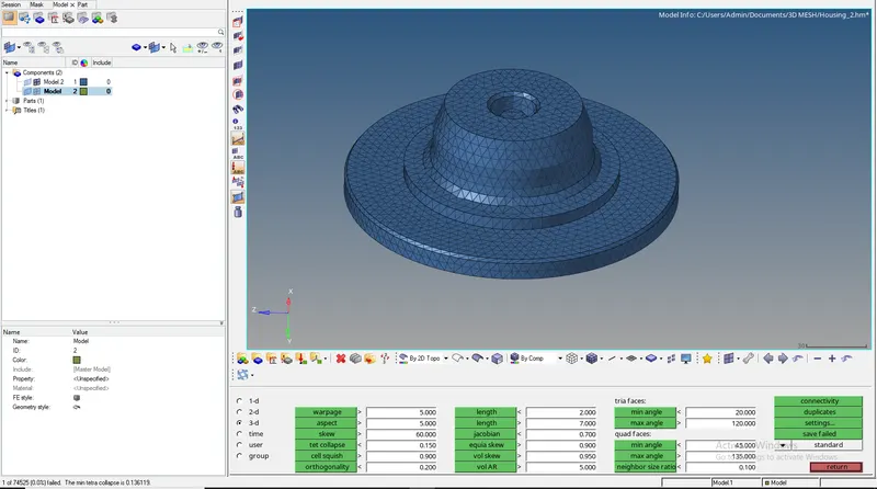
Here we can see that 1 element failed for tet collapse but the percentage failure, when compared to the total number of elements, is 0.0 % so it is acceptable. Now the 3 D tetra mesh is generated and I will delete the 2 D shell elements.
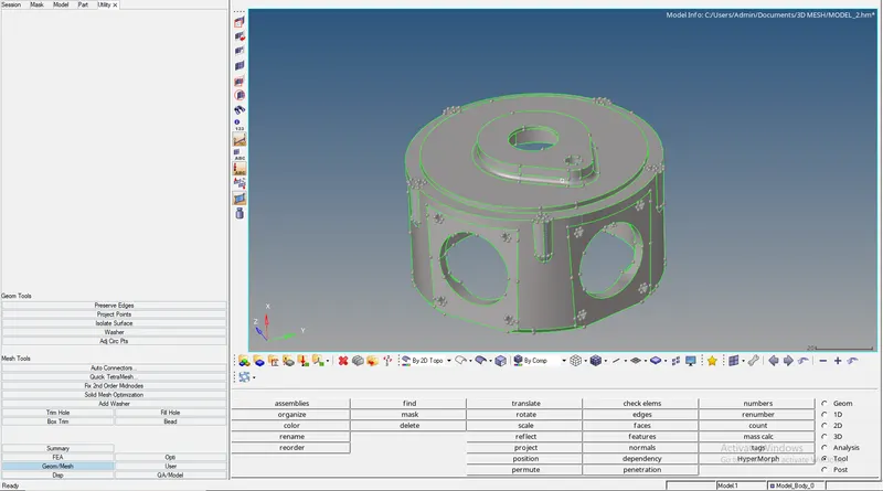
2) The second model after importing the model and deleting the solid is shown below:
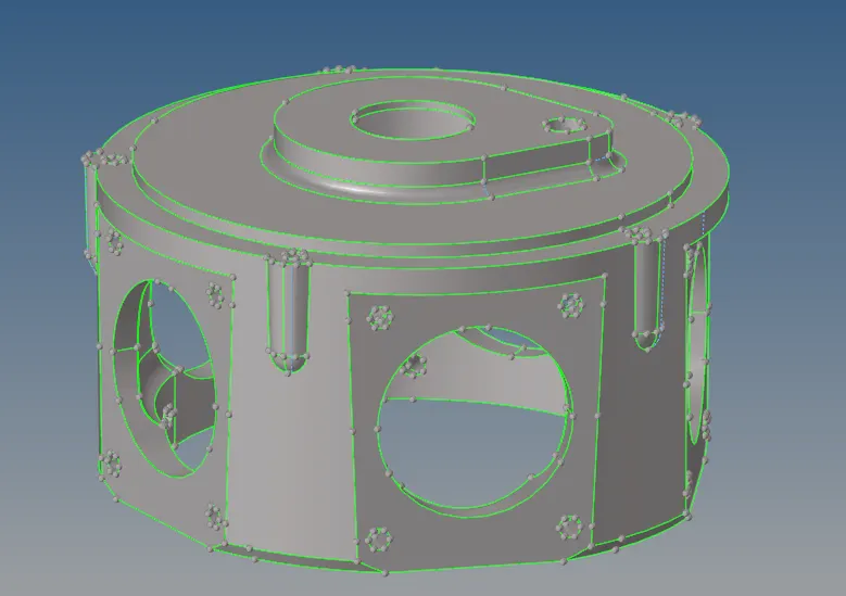
Now for this model, I have to generate the tetra mesh using the quick tetra mesh from the utility panel. so the steps I will follow are:
First, I will go to view then the browser and then select utility under hypermesh.
Then under the utility menu, select the geom/mesh, and under that select quick tetra mesh
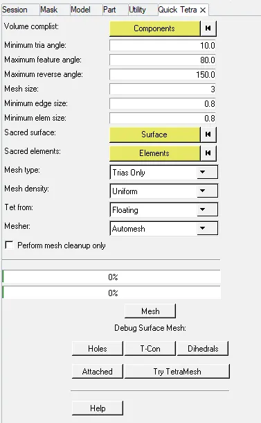
under the quick tetra mesh, I have to specify the mesh size and change the mesh type to trias only after selecting the component and surface. and then finally click on the mesh.
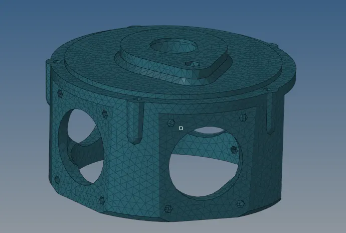
The tetra mesh of the model is shown below:
Now I will check for the tet collapse failure. on checking I found that 135 elements failed for tet collapse. Now to clear that element failure I will remesh the tetra mesh using the tetra mesh parameters. The parameters are shown below:

The final tetra mesh of the component is shown below:
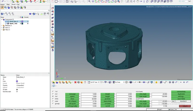
Here we can see that that are no tet collapse failures so now the model passes the quality criteria.
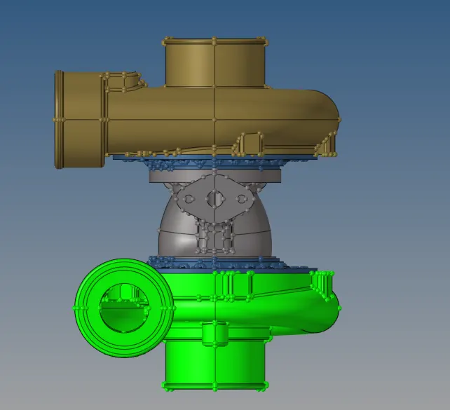
3) For the third model I have to generate the tetra mesh using the volume tetra mesh method. so here I won't delete the solid as I have to create mesh on the solid body. The model is shown below which comprises 5 components:
Now taking the first component
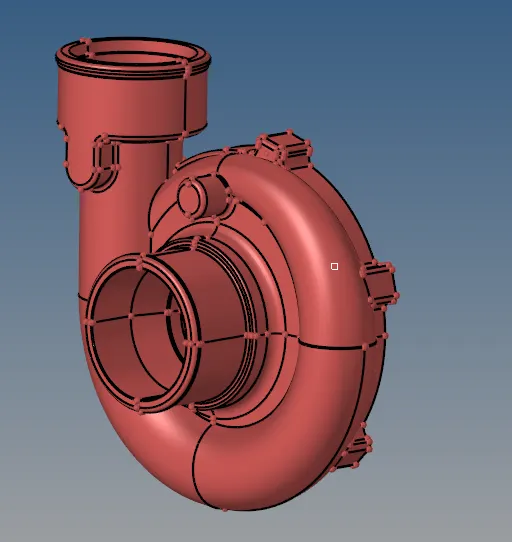
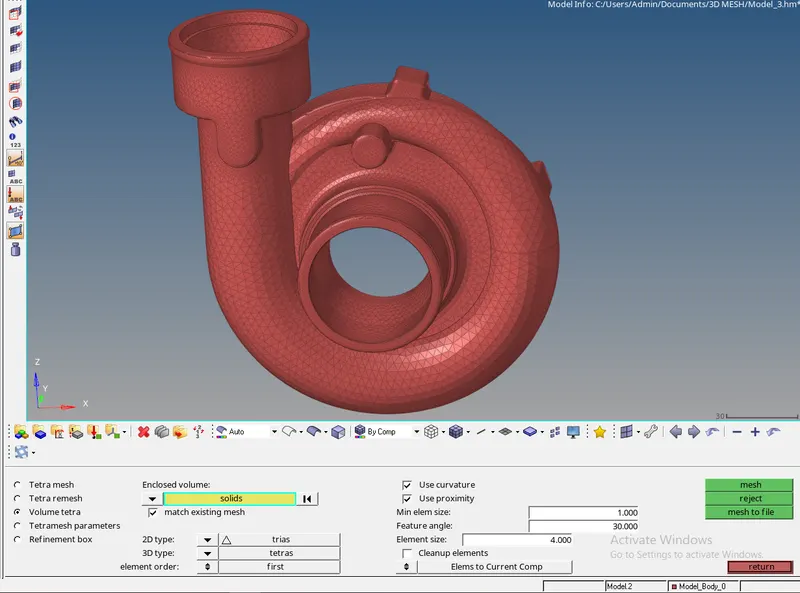
To create the 3 D tetra mesh I will just go to tetra mesh under the 3 D section and then select the volume tetra mesh and finally select the solid. The volume tetra mesh is shown below:
Now again I will remesh the 3 D tetra elements to clear the tet collapse failure. using the tetra remesh option under tetra mesh. But again I have to first set the parameters for tetra mesh. The parameters are shown below:

The final 3 D tetra mesh of the component is shown below:
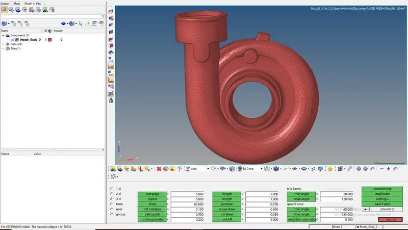
As we can see that there are no tet collapse failures so the component passes the element quality.
Now I will move on to the second component. The component is shown below:
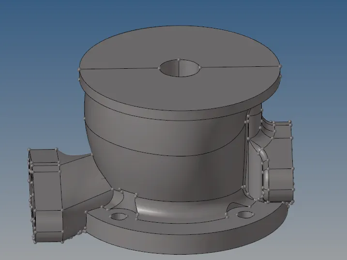
Next, I will simply mesh the component using the volume tetra method under the 3 D section. The mesh is shown below:
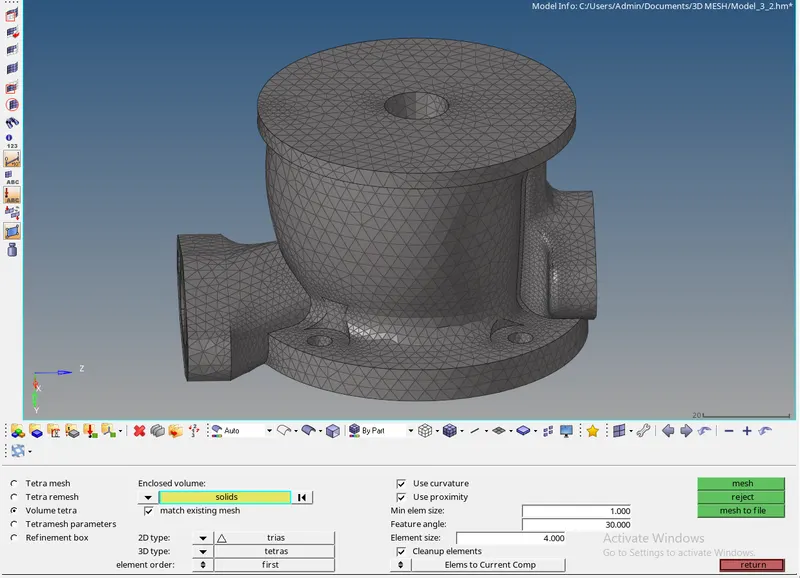
Now again I will remesh the 3 D tetra elements to clear the tet collapse failure. using the tetra remesh option under tetra mesh. But again I have to first set the parameters for tetra mesh. The parameters are shown below:
The final 3 D tetra mesh of the component is shown below:
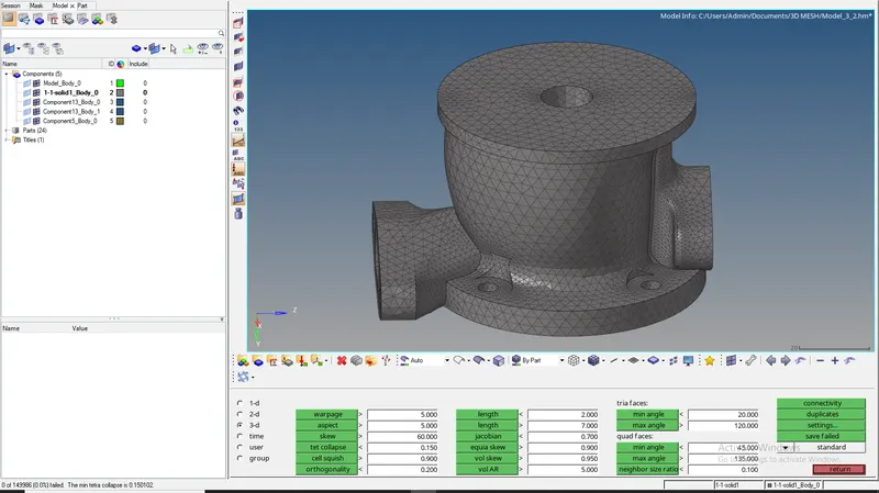
As we can see that there are no tet collapse failures so the component passes the element quality.
Now I will move on to the next component. The component is shown below:
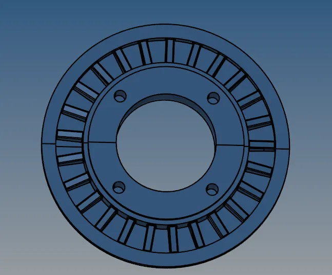
next, I will just simply mesh the component using the volume tetra mesh under the 3 D section. The volume tetra mesh is shown below:
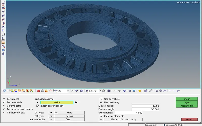
Now again I will remesh the 3 D tetra elements to clear the tet collapse failure. using the tetra remesh option under tetra mesh. But again I have to first set the parameters for tetra mesh. The parameters are shown below:
The final 3 D tetra mesh of the component is shown below:
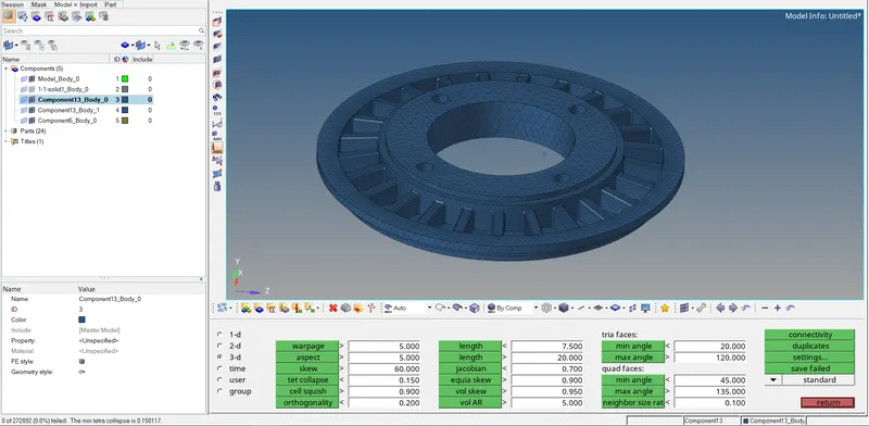
As we can see that there are no tet collapse failures so the component passes the element quality.
Now again I will move on to the fourth component. This component is also similar to the third one. The component is shown below:
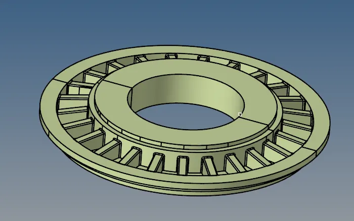
next, I will just simply mesh the component using the volume tetra mesh under the 3 D section. The volume tetra mesh is shown below:
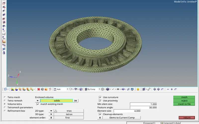
Now again I will remesh the 3 D tetra elements to clear the tet collapse failure. using the tetra remesh option under tetra mesh. But again I have to first set the parameters for tetra mesh. The parameters are shown below:
The final 3 D tetra mesh of the component is shown below:
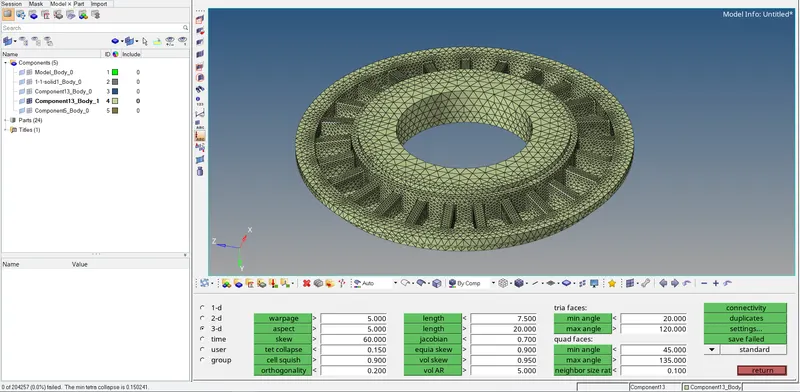
As we can see that there are no tet collapse failures so the component passes the element quality.
Now I will mesh the final component. The component is shown below:
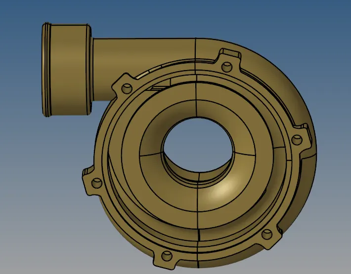
next, I will just simply mesh the component using the volume tetra mesh under the 3 D section. The volume tetra mesh is shown below:
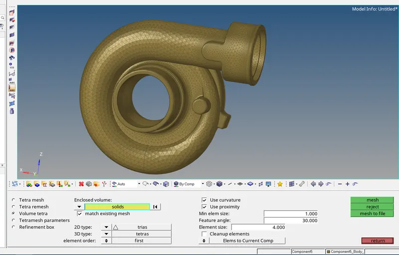
Now again I will remesh the 3 D tetra elements to clear the tet collapse failure. using the tetra remesh option under tetra mesh. But again I have to first set the parameters for tetra mesh. The parameters are shown below:
The final 3 D tetra mesh is shown below:
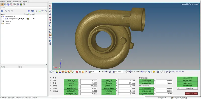
As we can see that there are no tet collapse failures so the component passes the element quality.
Now the generation of 3 D tetra mesh is completed on the complete model.
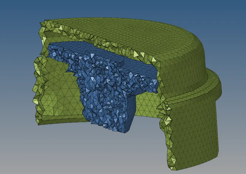
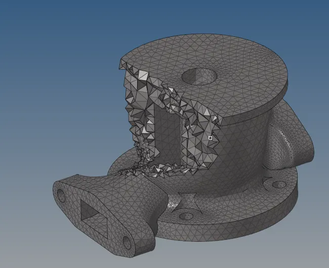
RESULT - 1) The 3 D tetra mesh of the housing model is shown below:
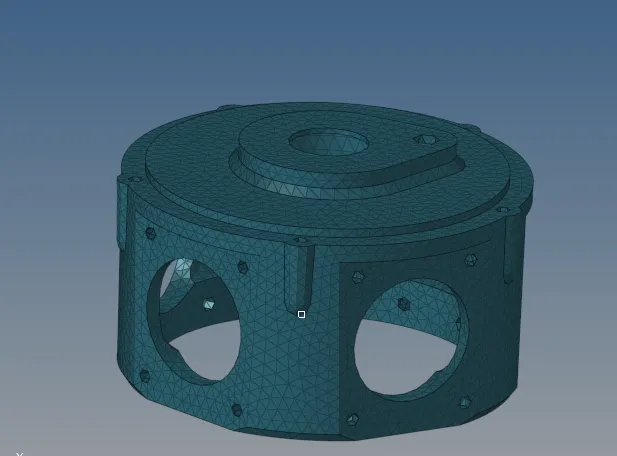
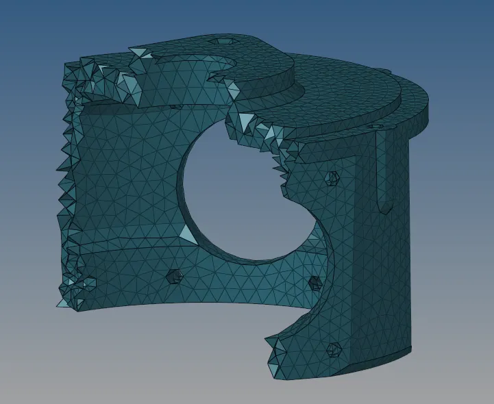
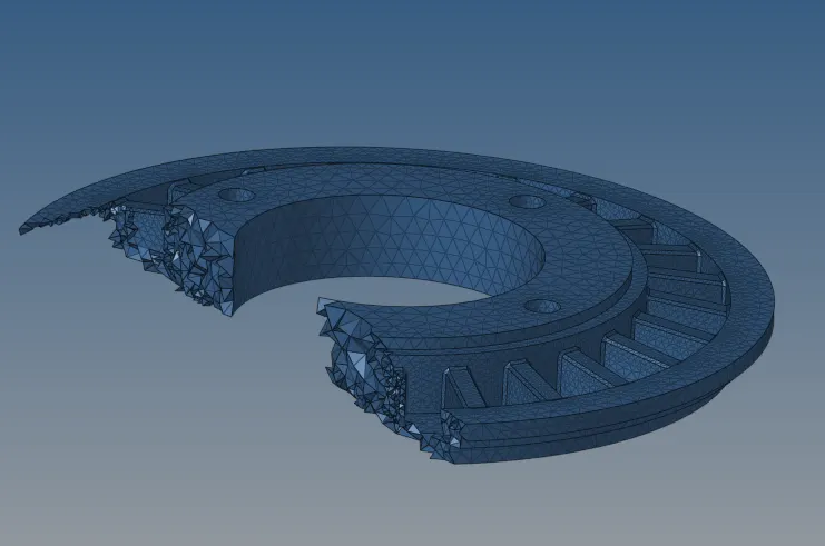
2) The 3 D tetra mesh of the second model is shown below:
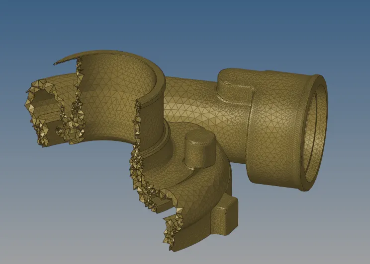
3) The 3 D tetra mesh of the third model is shown below:
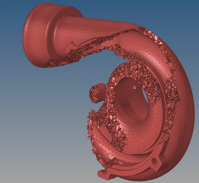
CONCLUSION - The creation of 3 D tetra mesh on the given model by different methods has been completed successfully and the results are shown.