Fender Design Challenge
AIM - To design the front fender along with the Drip area, A-pillar, sill, Bumper, and baffle mountings.
INTRODUCTION - FENDER is the term used for the part of an automobile, motorcycle, or other vehicle body that frames a wheel well (the fender underside). Its primary purpose is to prevent sand, mud, rocks, liquids, and other roads spray from being thrown into the air by the rotating tire. Fenders are typically rigid and can be damaged by contact with the road surface. some images of the fender are shown below:
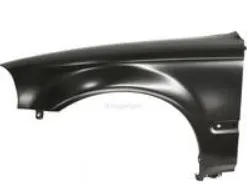
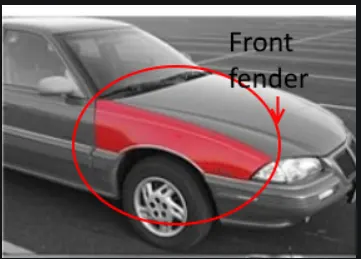
Sticky materials, such as mud, may adhere to the smooth outer tire surface, while smooth loose objects, such as stones, can become temporarily embedded in the tread grooves as the tire rolls over the ground. These materials can be ejected from the surface of the tire at high velocity as the tire imparts kinetic energy to the attached objects. For a vehicle moving forward, the top of the tire is rotating upward and forward and can throw objects into the air at other vehicles or pedestrians in front of the vehicle. so what the fender does is protect the engine compartment from the stones or small particles chipped by the wheels and prevent injuries for the pedestrians. A car has both a front fender and rear fender the rear fender is integrated with the body but the front fender is designed separately.
Types of Fender - The types of the fender are :
1) Full bumper type - They are the oldest and conventional type of fender which was used earlier but they are no longer in use.
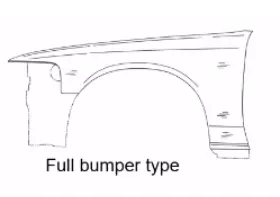
In the above image, u can see that the fender is covering the headlamp area which is unnecessary and it also increases the weight so that is why they are not used now.
2) Half bumper type - These types of fenders are commonly used worldwide here the fender does not cover till the headlamp area.
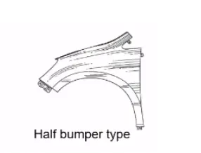
This type of fender is better to reduce the cost and also helps in reducing the weight.
The mounting points - To attach the fender to the car body we need to have the following mounting points:
1) Drip area mounting - It is the area in which the fender comes in contact with the engine compartment. The fender is attached to the engine compartment through fasteners.
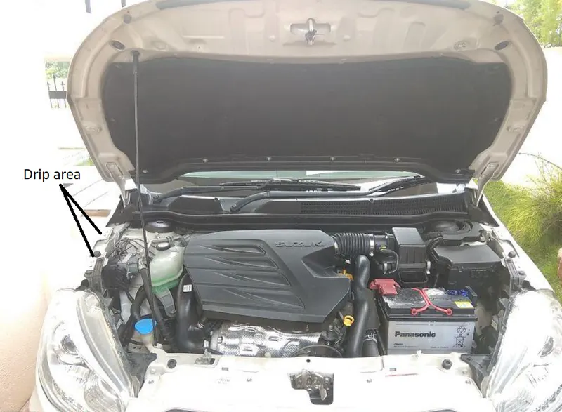
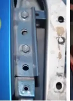
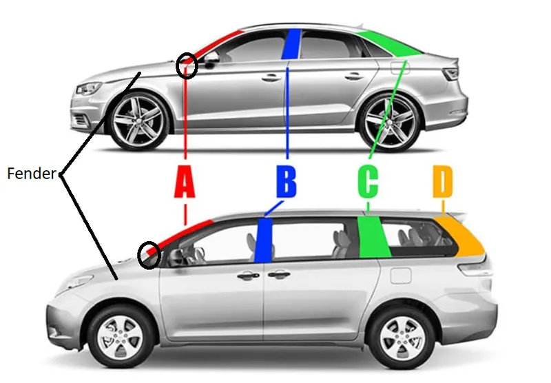
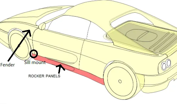
2) A-Pillar mounting - This mounting connects the fender to the A-pillar of the car. The "A" pillar holds the windshield in place. The A-pillar mounting is shown below which is highlighted in a circle
3) Sill mounting -The mounting area at the panel directly below the bottom of the door supporting the floor and may be used to combine the floor and body. The sill mounting region is shown below which is highlighted in a circle.
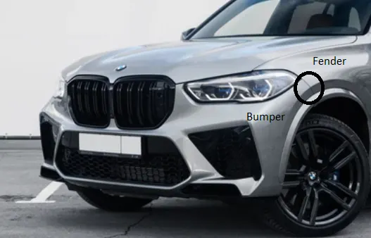
4) Bumper mounting - A bumper is a structure attached to or integrated with the front and rear ends of a motor vehicle, to absorb impact in a minor collision, ideally minimizing repair costs. This mounting connects the fender to the bumper of the car. The mounting is shown below which is highlighted in a circle.
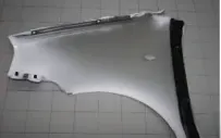
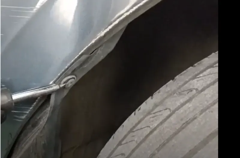
5) Baffle/splash mounting - Baffle is the rubber part that is attached to the fender so as to reduce the nice and vibration level which helps in increasing the performance of the vehicle. These mountings generally are given on the wheel arch area of the fender. The wheel arch is the semicircular part positioned above the wheel of a vehicle. It is important to design this area properly because the tires should not protrude outside the fender if seen from the front or top view. If they do so they will cause more chipping which will affect the performance of the vehicle and it won't be safe for the pedestrians as well. so the tires should lie within the fender. The baffle mounting is shown below:
PROCEDURE Here the class A surface is given to me as the input. The class A surface of the fender is shown below:

For the above Class A surface of the fender, I have to design the mounting points so that they can be connected to the body of the car.
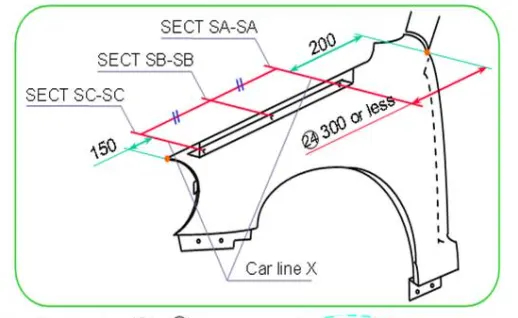
First creating the Drip area mounting - Drip area as already mentioned earlier it is the area in which the fender gets connected to the hood. There are few design considerations that we have to keep in mind while designing this area. From the backside of the front fender, there will be 200 mm clearance for the cowl (plastic parts that have viper installation points) mounting area. And from the front side, there will be a clearance of 150 mm for the headlamp housing unit. The remaining area we can use for the drip area. The drip area should not reach the engine compartment so the length should be 40 mm or less. The master section given to me for designing is shown below:
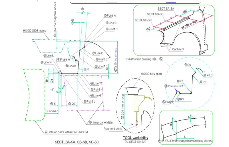
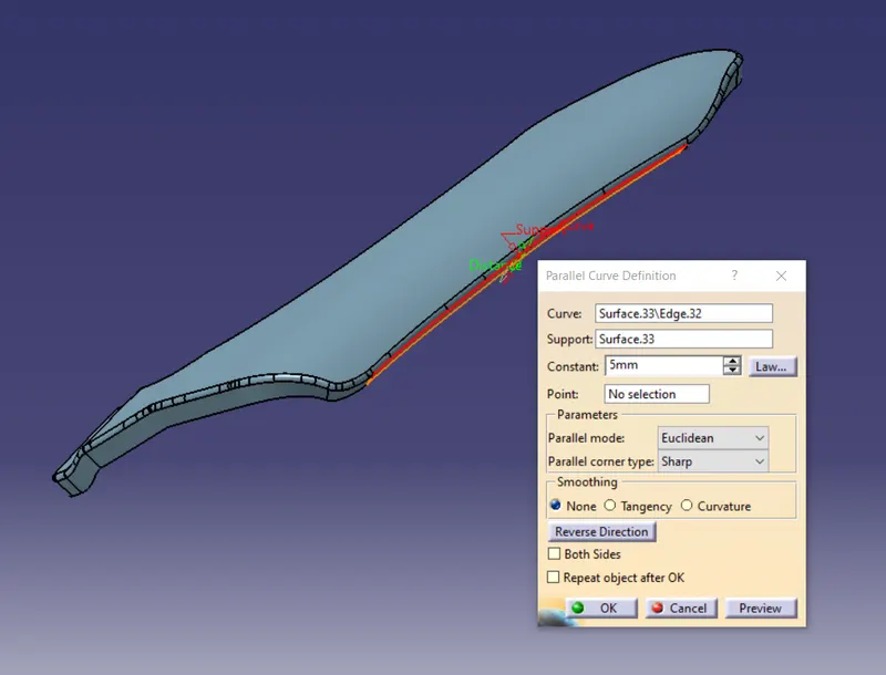
so I will start by offsetting the fender edge using the parallel curve feature. And I will offset it to 5 mm. The parallel curve is shown below:
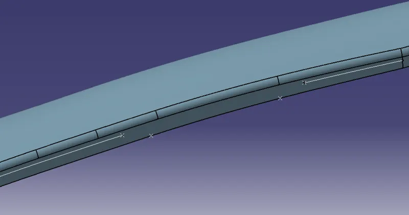
then I will just make points on the parallel curve and lower edge of the fender and split it into two parts using the points on the parallel curve. The split is shown below
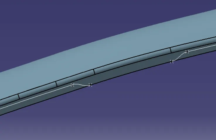
now I will connect the points using the connect curve option.
Then I will extrude the lines and curve after joining them the extrude of both curve is shown below:
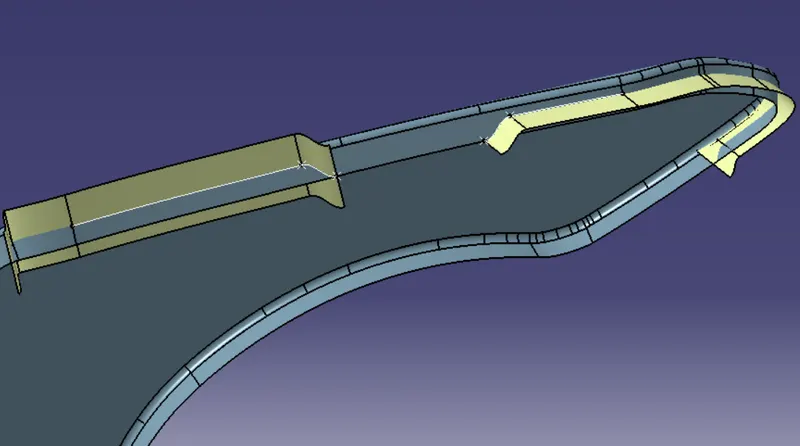
Then I will just split the extrude with the lower surface of the fender to get the drip area. The split is shown below:
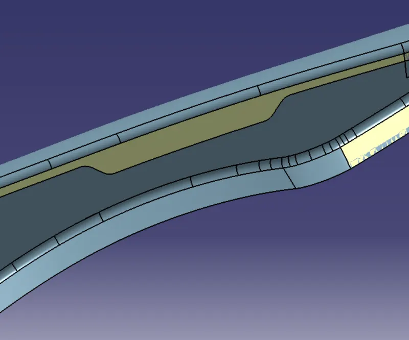
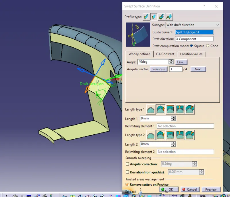
here I got my mounting surface now according to the master section given I will create the drip area. For creating the area is I will use the sweep command. After sweeping the surfaces I will just give the required fillets to make it smooth. The drip area according to the master section is shown below:
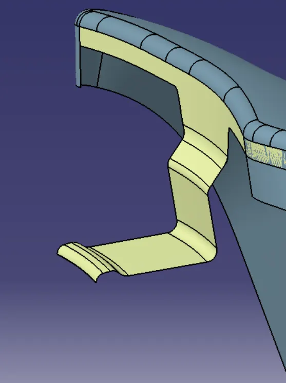
Now I will create the emboss on the drip area, Emboss is provided to increase the strength of the drip area and holes are created on the emboss for joining the fender with the BIW frame. For creating the emboss I will just create one plane and create a sketch on that plane. Then I will project the sketch on the drip area and split it. The split is shown below:
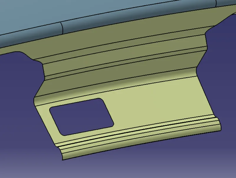
The embossing will be created on the inside area so I will sweep the sketch inside. The sweep is shown below:
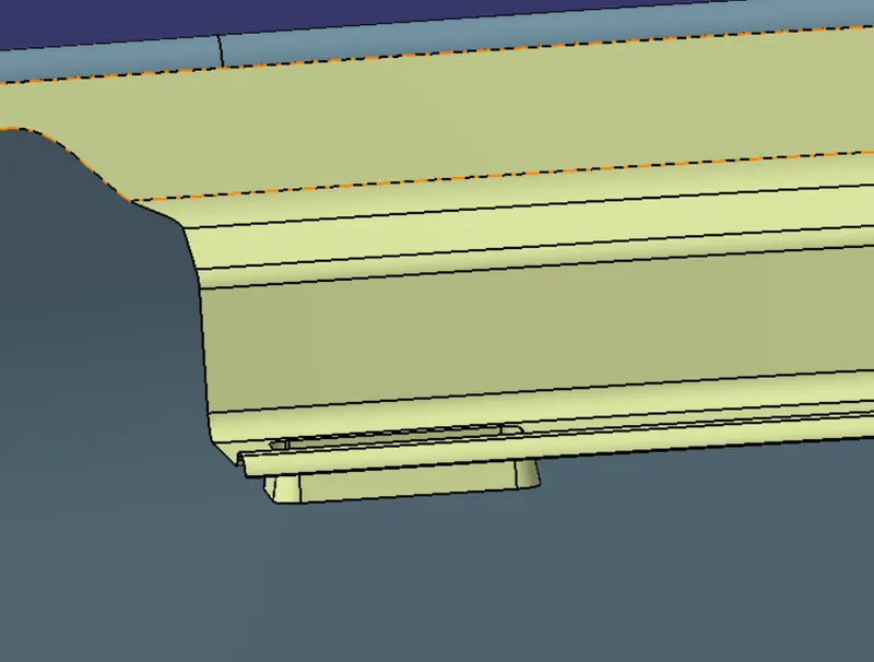
Then before splitting I have extracted the base surface of the drip area so I will offset that extracted downwards to 4mm and trim it with sweep later providing the fillets. The area after providing the fillets looks like this:
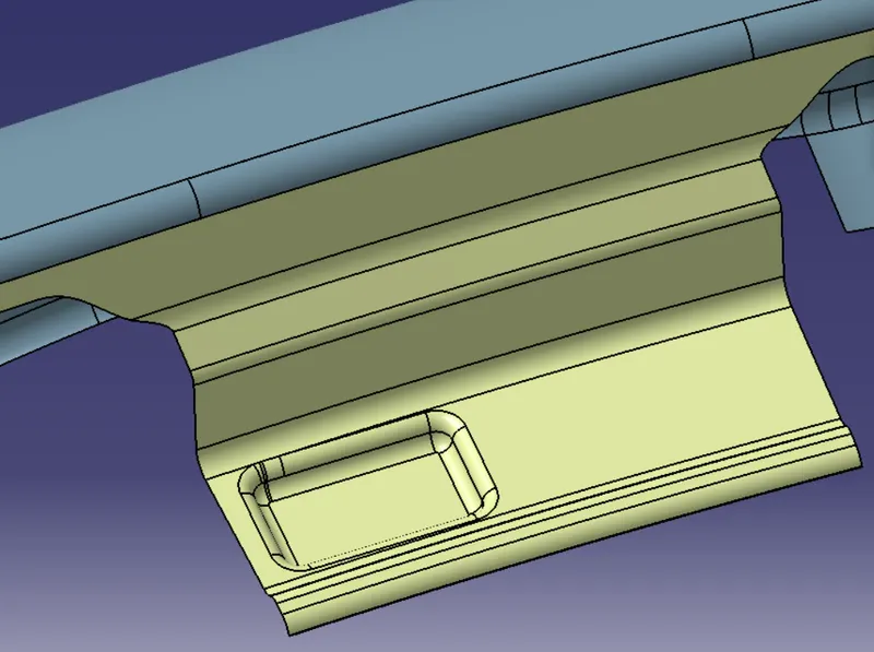
Then similarly I will another emboss on the drip area using the same plane. The other emboss is shown below:
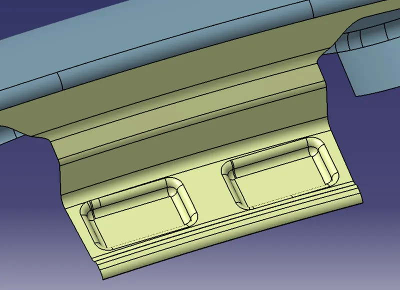
Then I will create the holes. So for deciding the dimensions of the hole I have to keep in mind that there should be a 3- 5 mm flat surface around the embossing. so I will create a sketch on the same plane and split it. The holes that will be used for joining are shown below:
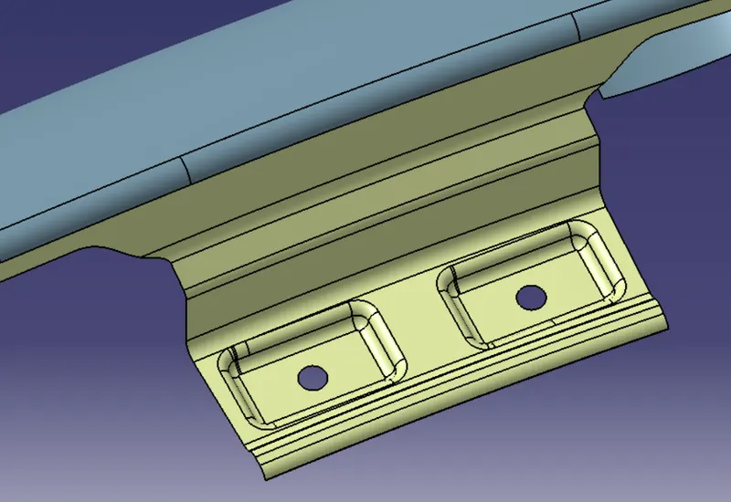
Here on the drip area, the ribs will be provided that will increase the strength even more and also reduce the spring back effect and NVH.
Now following the same procedure as I did for the drip area I will create the other mounting areas.
Bumper mounting - For creating the bumper mounting I will again offset the edge, make points on the edges, split the parallel curve, use the connect curve to connect the points then extrude and split the lower surface of the fender with the curves then create the embosses, provide fillets to the embosses and make the holes.
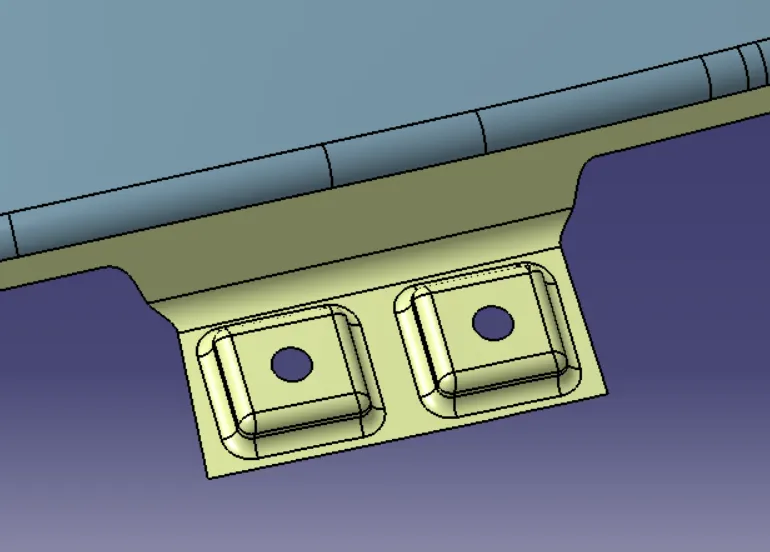
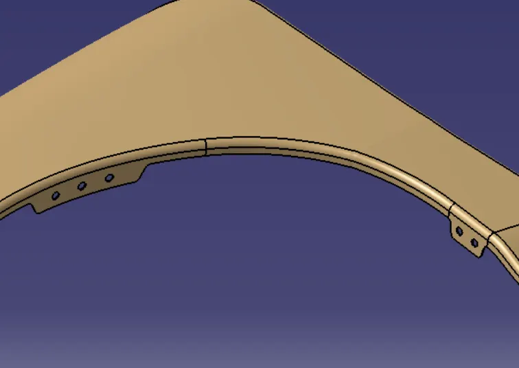
Baffle mounting - For creating the baffle mounting again I will follow the same procedure. But here I won't be creating any emboss because the baffle mounting I will be creating will be on the wheel arch area and for that area, there is no need of creating emboss. Baffles will be provided on the flat surface so I will be creating the holes only. The baffle mounting is shown below:
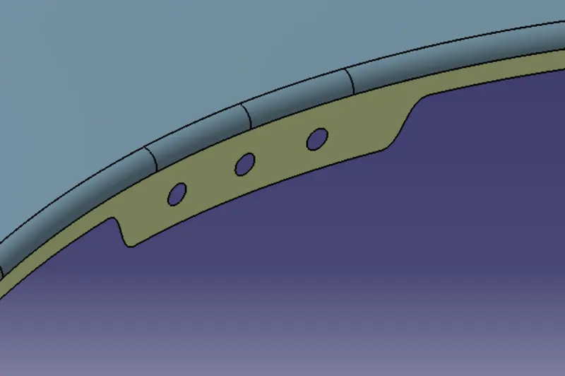
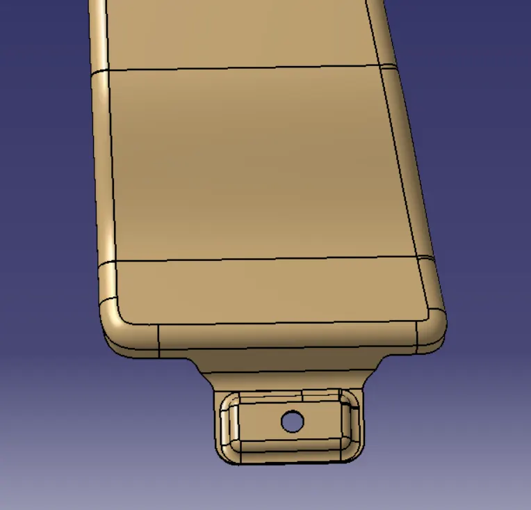
Sill mounting - For creating the sill mounting I will again follow the same procedure. Here again, I will be creating the emboss following the same procedure as I did earlier. the sill mounting is shown below:
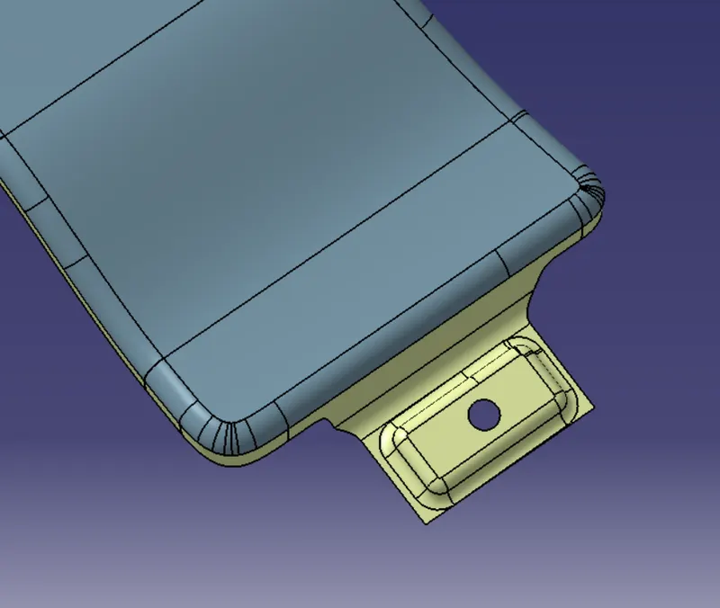
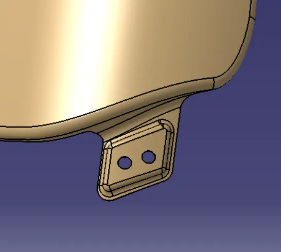
A-pillar mounting - A-pillar mounting as I already mentioned will connect the fender to the A-pillar of the car. For this, also I will follow the same procedure for creating the mounting and the emboss. The A-pillar mounting is shown below:
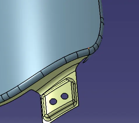
Now after creating all the mountings I will join all the mounting surfaces with the top surfaces of the fender to make a single surface body. Then I will just thicken the body to 0.75 mm to create a solid body from the surface body and will provide the fillets to the mounting corners to make it smooth.
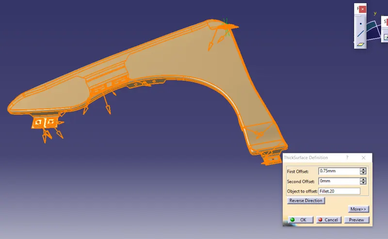
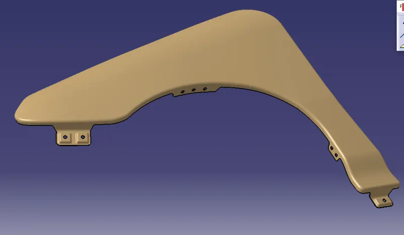
RESULT - The solid of the fender was created with the necessary mountings which are shown below:
1) The drip mounting -
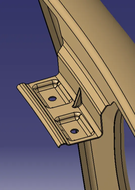
2) Bumper mounting -
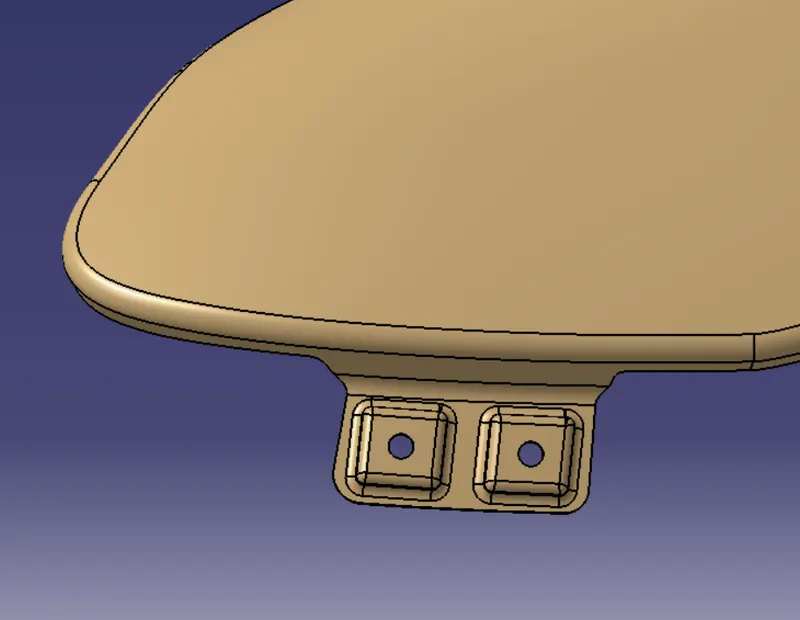
3) Baffle/splash mounting -
4) Sill mounting -
5) A-pillar mounting -
The whole fender is shown below:
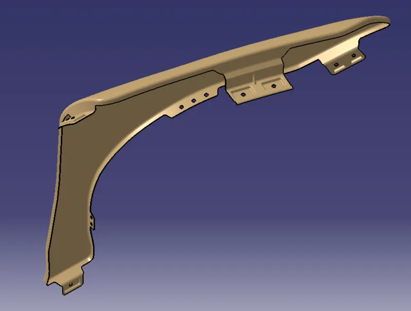
CONCLUSION - This concludes the design of the front fender along with the Drip area, A-pillar, sill, Bumper, and baffle mountings.