Week 9 - Project - Master Section Development
AIM - To create the B pillar solid part using the class A surface and to create the engineering features on it and to perform the draft analysis on the component.
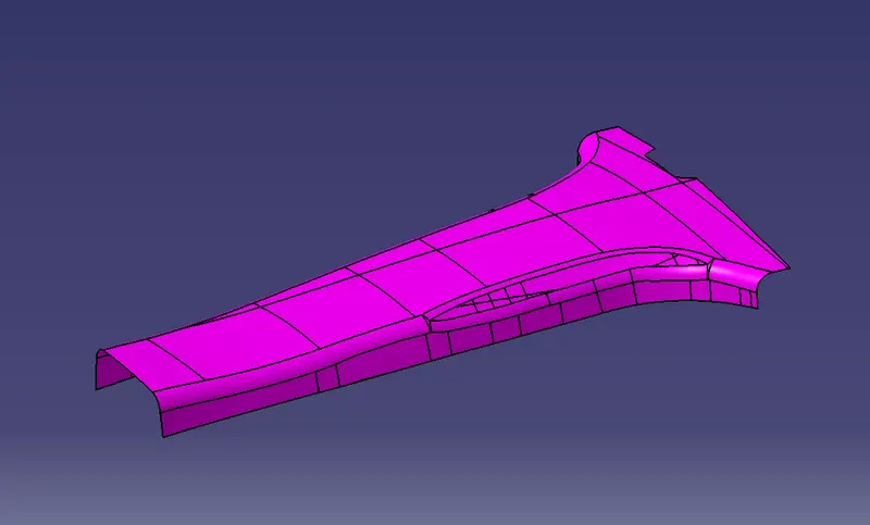
PROCEDURE - The class A surface given to me is shown below:
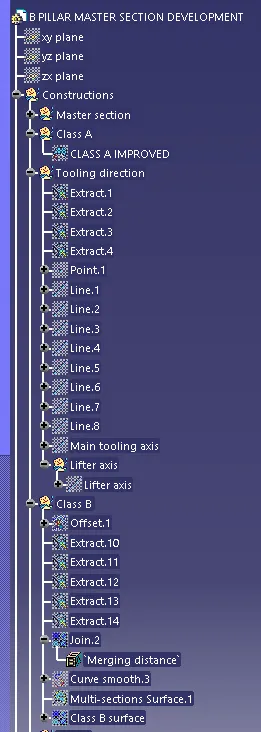
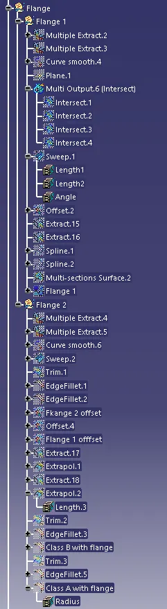
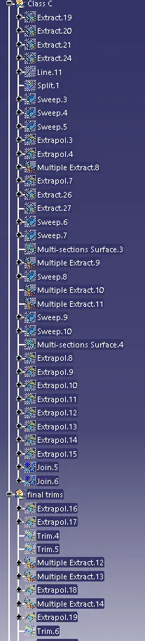
The tree structure performed for creating the whole component is shown below:
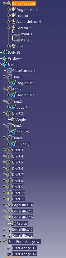
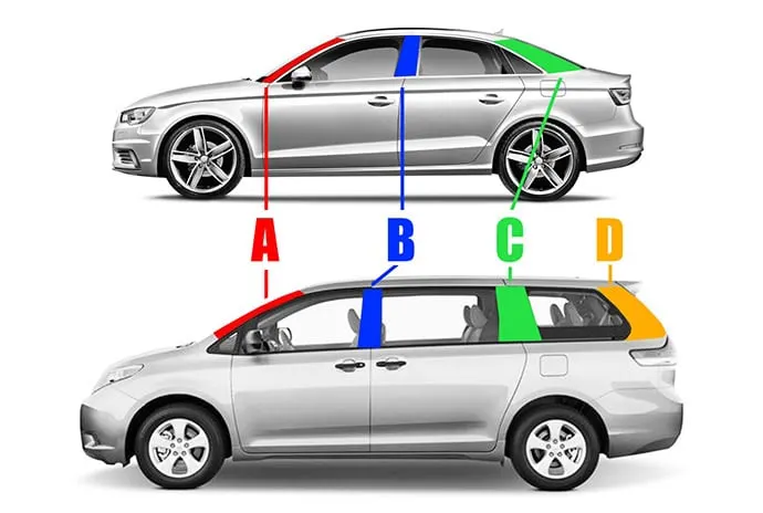
Let's first see what is B pillar
B pillar - The vertical roof support structure located between the front and rear doors on a typical vehicle. It corresponds with the A-pillar located on either side of the windshield at the front of the car and the C pillar which sits on either side of the rear window on a typical sedan. On SUVs, minivans, and wagons with extended cargo areas, the c pillar is the vertical structure behind the rear door while the vertical supports at the rear of the vehicle are called D pillars.
so here A surface is given to me so first I have to find the tooling axis
Tooling axis - The tooling axis is defined as the direction in which the mold opens or core and cavity opens and closes. The selection of the correct tooling axis is important to ensure the component is taken out perfectly and also the cost of the component should be less.
I will start by inserting a geometrical set and naming it as a tooling direction. For creating the tooling axis I will analyze the model and see from which direction I can see the whole model. so here the direction I have chosen for the tooling axis is along y-direction because along y-direction the whole model is visible properly.
so here the master section is also given to me.
Master section - Master section are the guides for a design that shapes the component after technical styling of class A surface. The Master section is parameterized model of the vehicle body that outlines the guidelines for the NPD team. The master section given to me is shown below:
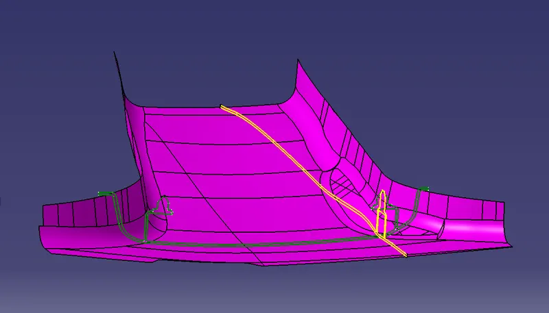
For creating the tooling axis I will just the lines that would cause problems during the ejection. So basically I will extant the master section lines and some of the surface lines that are perpendicular to an imaginary tooling axis along y-direction so the lines I have created is shown
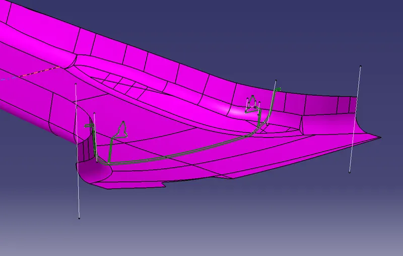
I have also created one point and from that point, I will create the bisecting lines which would bisect the lines I have created from the surfaces.
The bisecting lines are shown below:
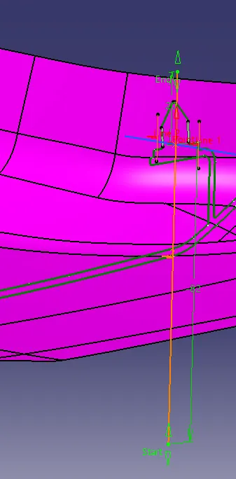
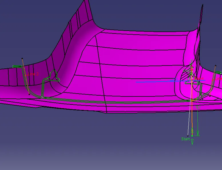
Now I have bisected the above lines.
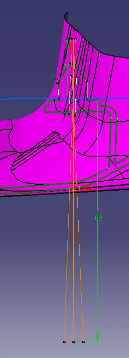
Then i have created one more bisecting line which is shown below:
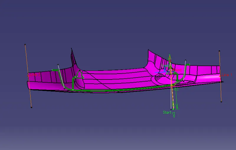
and I have bisected the above line with line 5 to get my tooling axis. The parameters of the tooling axis are shown below:
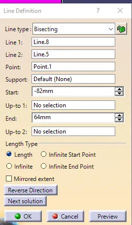
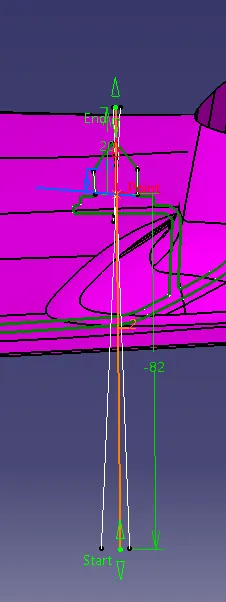
The main tooling axis is shown below:
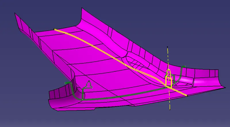
After the creation of the tooling axis, I will perform the draft analysis on the class A surface.
Draft analysis - Draft analysis is a technique to analyze whether the component created is manufacturable or not based on the draft conditions applied. So here I will provide the direction in which the component should be ejected to get the easy removal. My direction will be the tooling axis that I have created.
The minimum draft value for the Automotive plastic component is 3 degrees and those for the texture faces 7 degrees od draft is suitable. The draft is provided to the component for easy removal from the mold in the case of a plastic component.
So here I will change the customize view parameters and will select the material mode.
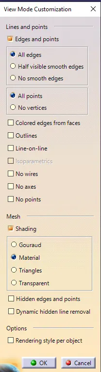
Then I will go insert and select the analysis and in the analysis, I will select the draft analysis. The draft analysis block is shown below:
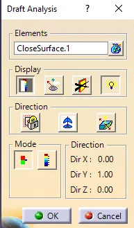
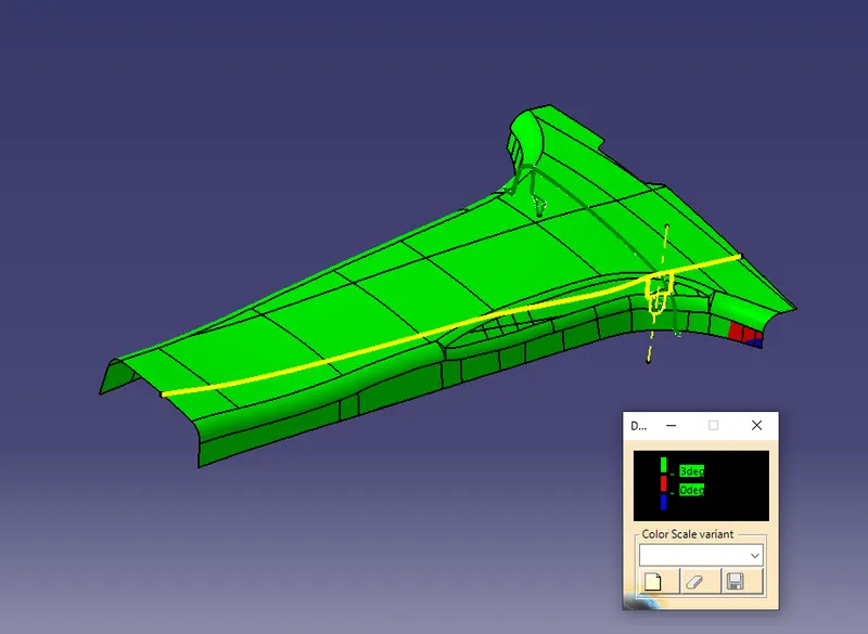
In the above fig. under the display section select the color scale and turn on the light effect for proper visualization. then under the direction section, I will click on the compass and will drag the compass from vehicle zero to my tooling axis. and then I will click on the lock feature and will select the class on the surface. The result is shown below:
The color scale is shown below:
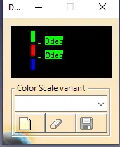
In the above fig. The Green color shows that the draft provided is more than3 degrees
The Red color shows that the draft provided is between 0 and 3 degrees
The Blue color shows that the draft provided is negative
so from the result u can see that there is a small patch that has a negative draft that means that there is some problem with the class A surface.
rest of other areas are drafted.
so now I will create the class B surface
Class B surface - It is a surface that gives thickness from a class A surface. All the supporting features of the component will be formed on the B surface only. so we can say that Class B is an engineering surface and Class A is an aesthetic surface.
so here I have offset the class A surface to 2mm because 2 mm is the thickness I want. The offset is shown below:
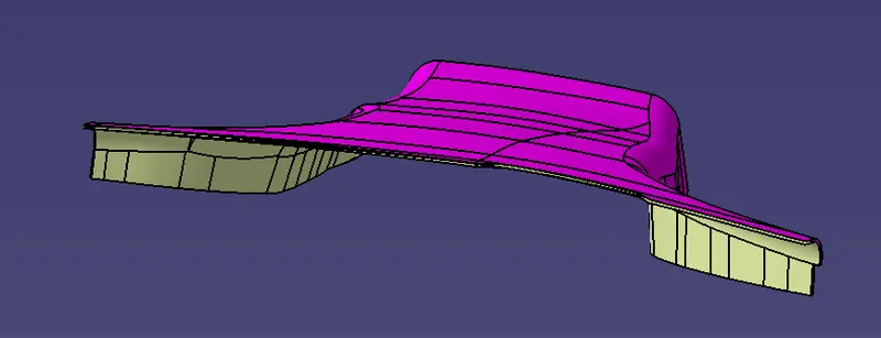
During the offset, if any empty patch is there I have done the multisection surface to fill that patch and then join it to get the class B surface. The Class B surface is shown below:
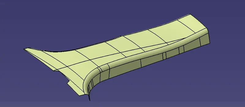
Then i have created the flanges on both Class A and Class B surfaces.
so for creating the flanges I have extracted the boundaries and surfaces of class B it is shown below:
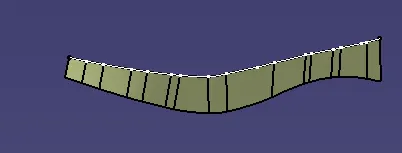
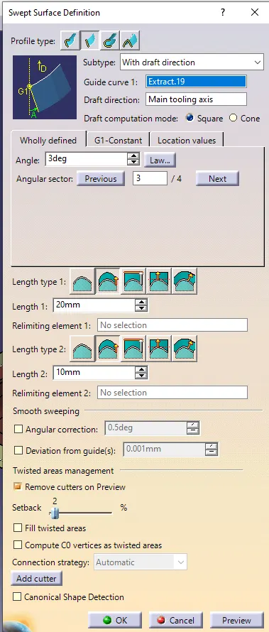
Then I have swept the boundary extract. The sweep parameters are shown below:
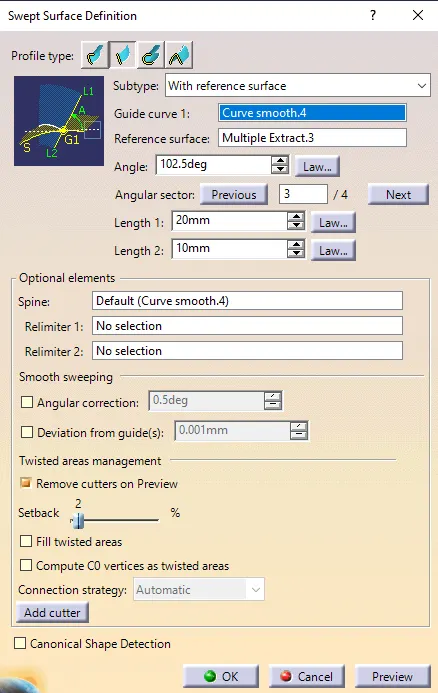
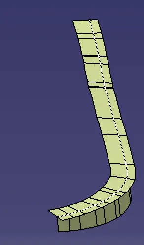
Then I have offsetted it to 2 mm to get create the flange of class A The offset is shown below:
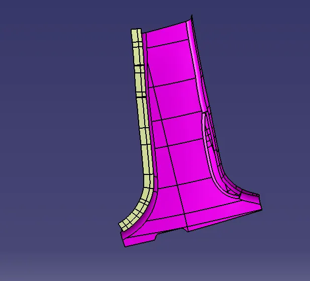
Then I have created the same flange on another side also
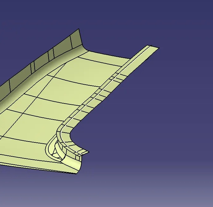
Then I have trimmed both the flanges with class B and provided the fillets. The trim is shown below:
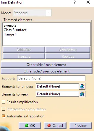
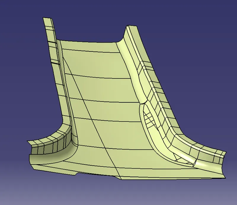
Then after offsetting I have trimmed it with class A surface to get the flange of class A
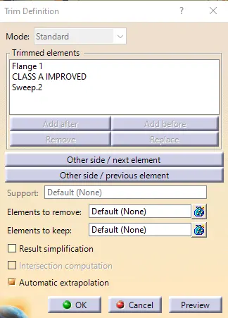
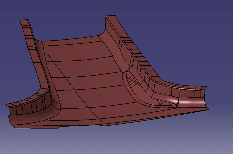
Then after creating the flanges for A and B surfaces I have created the class C surface.
The class A and class B surfaces with flanges are shown below:
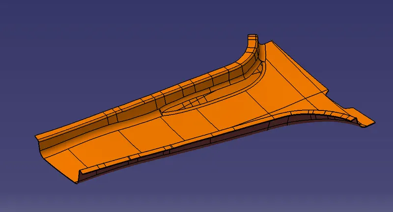
CLASS C SURFACE - Class C surface is defined as the surface which connects the CLASS A and CLASS B SURFACE along the tooling direction. The tooling direction here will be my tooling axis.
For creating the class C surface I will extract the boundaries from the class A surface.
The extract is shown below:
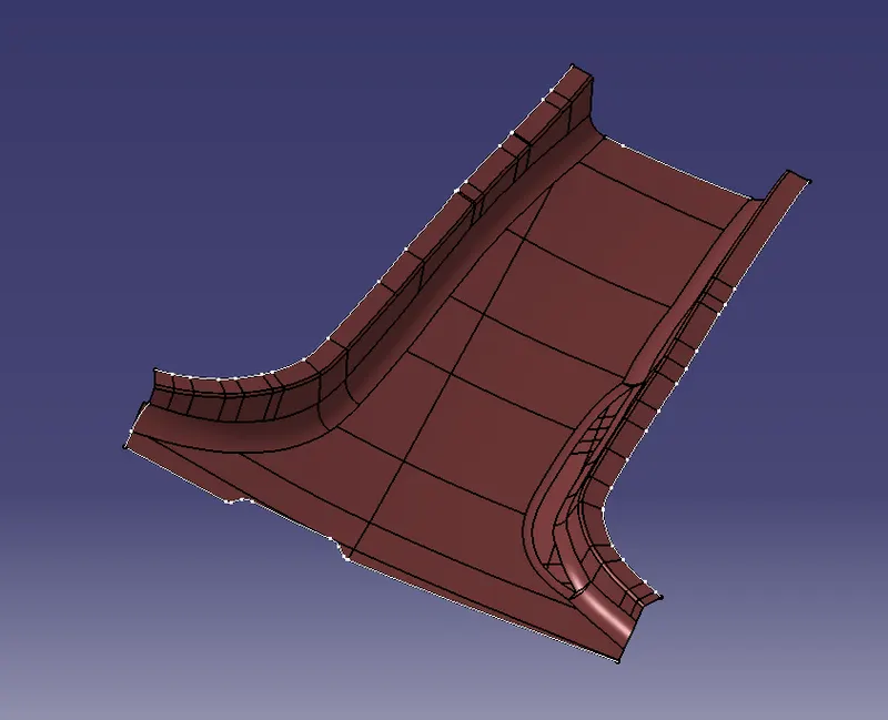
Then I will sweep the extracts along the main tooling axis. The sweep is shown below:
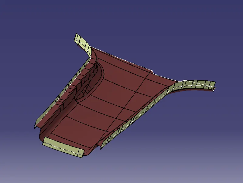
NOw i have done some extrapolation to get the back part of the B pillar.
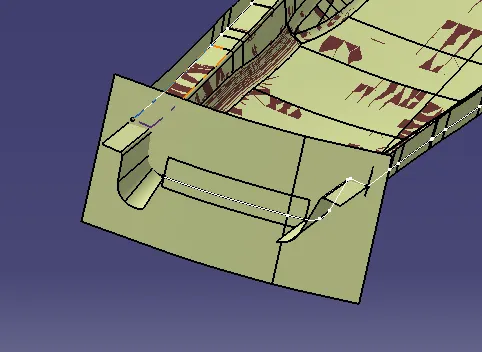
For creating the C surface for the sides I have extracted the boundaries and swept them equally to get equal surfaces and then used the multisection feature to combine them. so I have done this for both sides
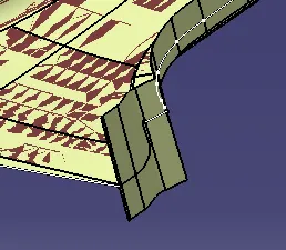
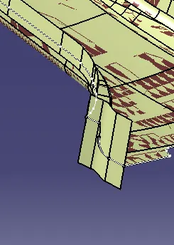
Then I have joined both the multisection with the B pillar and trimmed it with the B surface
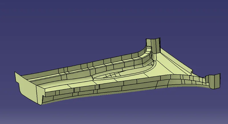
Then I have done the final trim that is trimming with A surface to get the part surface. The part surface is shown below:
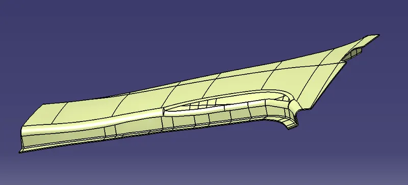
Then I have created the solid body from this close surface using the close surface feature in part design. The solid part is shown below:
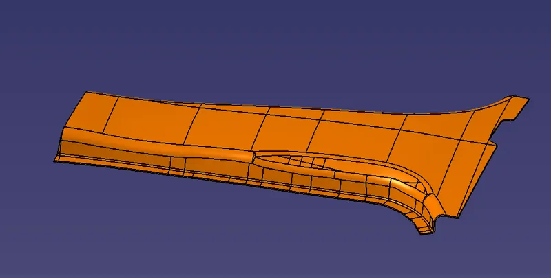
Then I have created The B side features
I have started with the dog house
Dog House - Dog house is an engineering feature used in the plastic trim design. Doghouses are used as supporting features. Sometimes other engineering features like snaps; locators, etc. are mounded on them to increase their strength. Dog houses are subjected to draft analysis to prevent breakage of the component during ejection from the mold cavity. Dog house and other engineering components are built on B-surface.
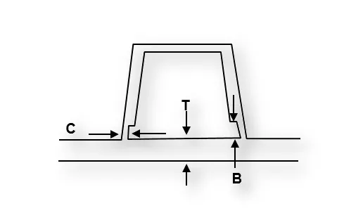
The design guidelines regarding the dog house are shown below:
"C" is where the doghouse contacts the backside of the surface
-
Doghouse wall thickness at the intersection of the part wall ( C ) should be 40% or less than the main wall stock ( T ).
-
Height of ( B ) should be between 3.0 – 6.0 mm
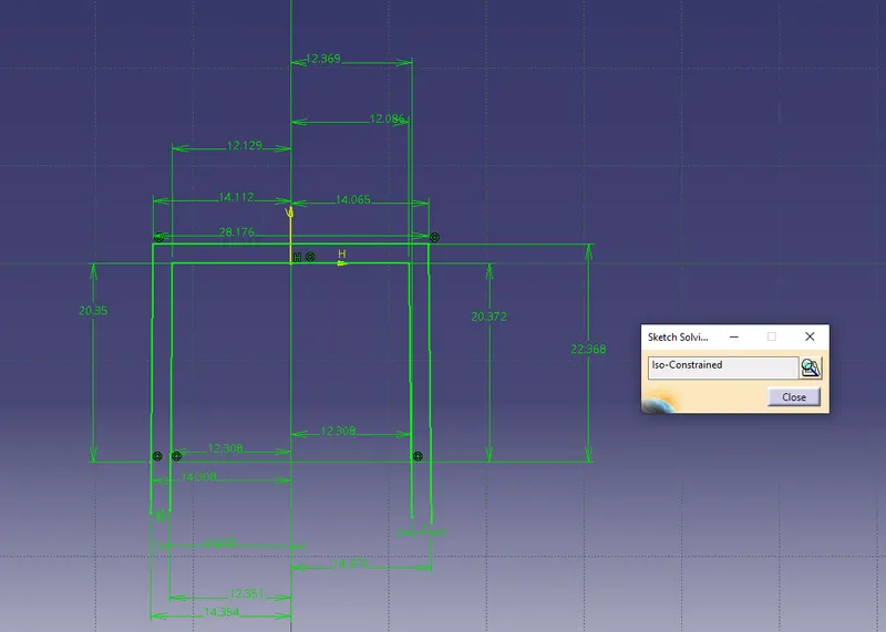
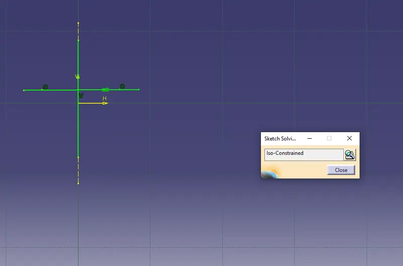
So for this, I have used the master section for creating the sketch. the sketch is shown below:
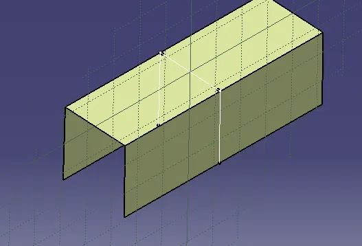
Then i have extruded it and closed the surface
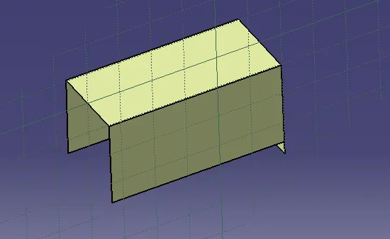
Then to get the inner portion of the dog house I have extracted the surfaces from Class B and trimmed it
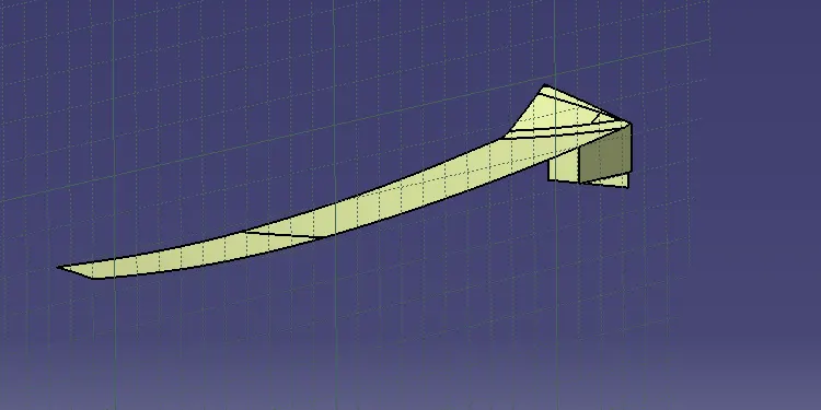
Then i have splited it
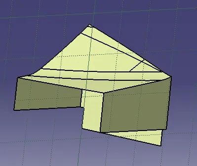
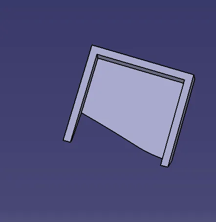
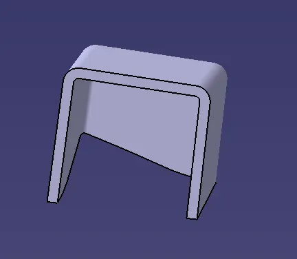
Then I have provided the fillets to the body
'
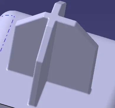
Then I have created the locators on the top of the dog house again using the master section
Then I have padded the sketch and provided the draft, fillets, and chamfer
And I have this locator body to the dog house body
then for avoiding the sink marks, I have extracted the inner surfaces from the B surface and the base surfaces of class B surface and I have offsetted it and splited it.
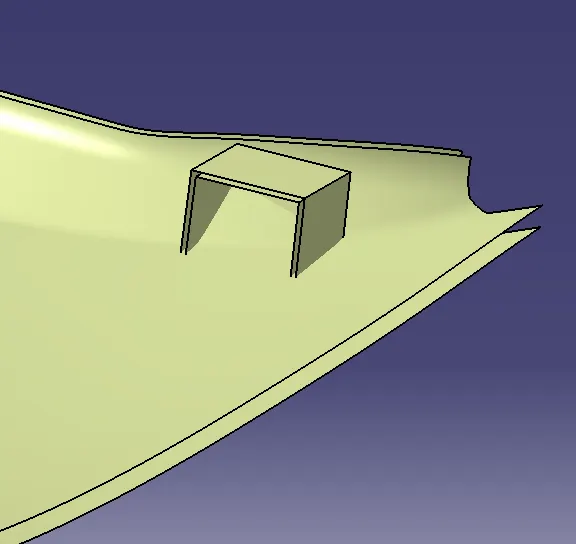
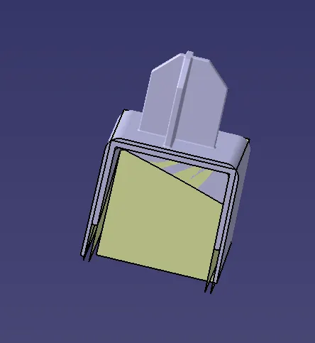
Now the dog house is complete and I will do the draft analysis on the dog house here the inner portion of the dog house will not be cleared using the main tooling axis so for that I will create another tooling naming it as lifter axis.
From the point that I created earlier when I created the dog house from that point, I will create one line along plane 2 and that line will be my lifter axis. The lifter axis is shown below:
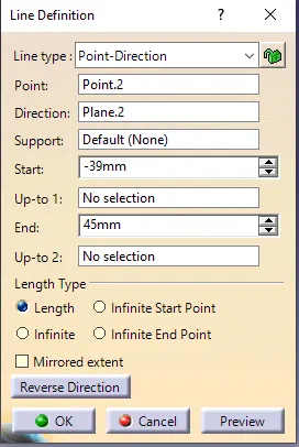
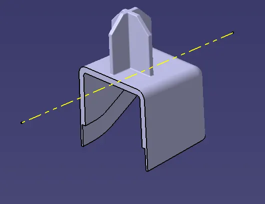
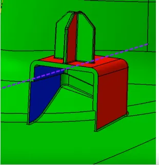
Now I will do the draft analysis using the lifter axis The result of the draft analysis is shown below:
The color scale is shown below
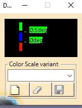
In the above fig. The Green color shows that the draft provided is more than0.5 degrees
The blue color shows that the draft provided is between 0 and 0.5 degrees
The red color shows that the draft provided is negative
now the inner portion of the dog is also clearing. The outer portion will be cleared using the main tooling axis.
So now I will symmetry the dog house to another side.
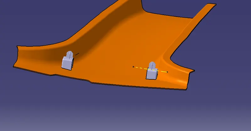
After designing the dog house and locators I will design the ribs.
Ribs - Ribs are a feature in plastic injection molded parts. They are thin extensions that run perpendicular to a wall or plane. They are commonly used to provide additional support and strength to a part.
For creating the ribs I have made the following sketch:
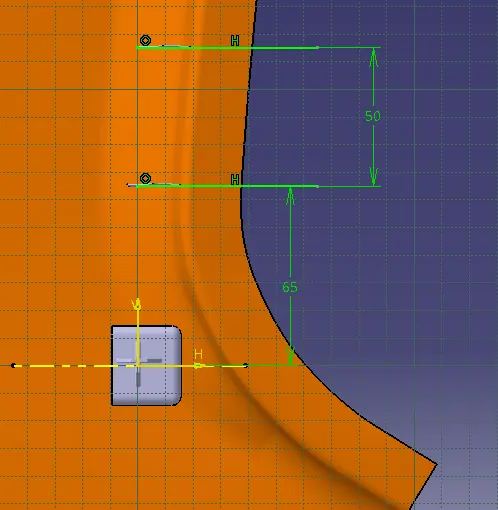
Then I have extruded the above sketch. The extrude is shown below:
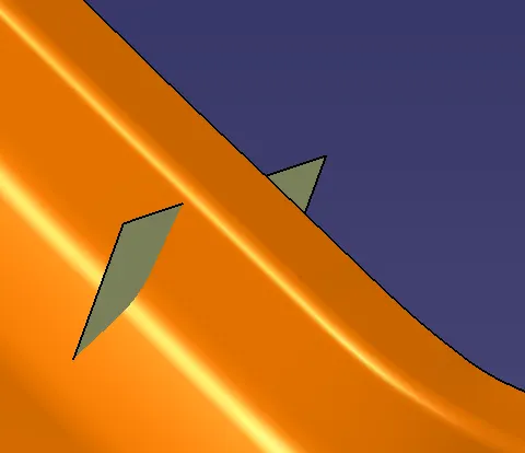
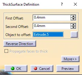
Then I have thickened it. The thick surface parameter is shown below:
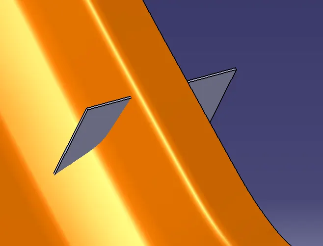
Then I have extracted the surfaces from class B which surrounds the ribs and offsetted them to 10mm to satisfy the design rule for ribs. the extracted surface is shown below:
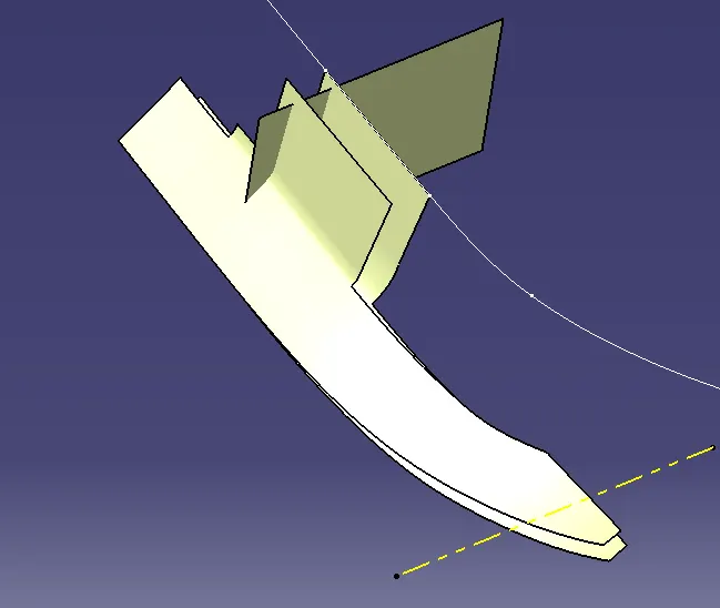
Then I have split the offset surface with the ribs body and union trimmed with the pillar body. The result is shown below:
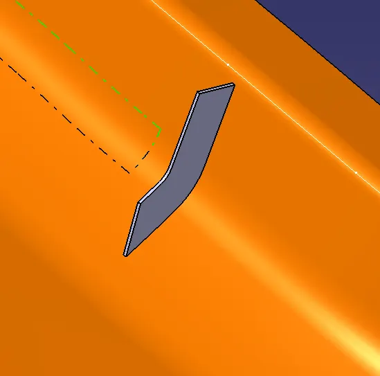
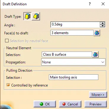
Then I have provided the minimum draft on the ribs.
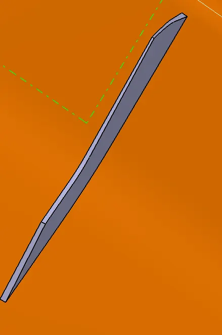
Then I have made copies of the ribs body and translated it to 50mm along the B pillar body and also I have used the rotation parameter to rotate it to the other side and again translated it to that side also.
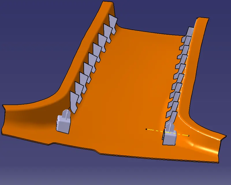
Then at last I will provide the fillets to the ribs. The fillets are shown below;
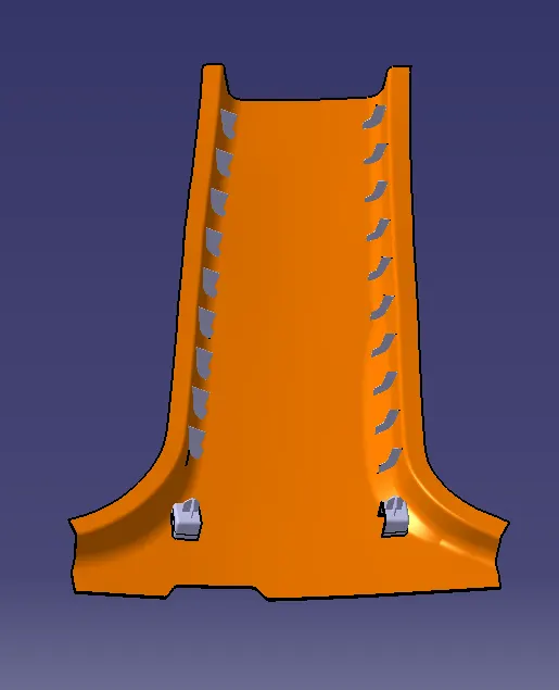
Now the part is completed and next, I will do the draft analysis of the ribs with respect to the main tooling axis
so again I will change the mode and in the insert, I will go to analysis and select draft analysis. The draft analysis is shown below:
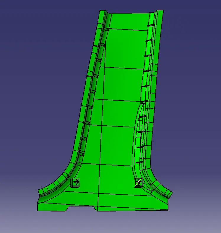
the color scale is shown below:
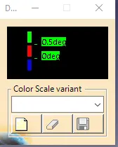
In the above fig. The Green color shows that the draft provided is more than0.5 degrees
The Red color shows that the draft provided is between 0 and 0.5 degrees
The Blue color shows that the draft provided is negative
RESULT - Here I have created the B pillar solid part using the class A surface along with the Engineering features and also i have performed the draft analysis on the component and the result is shown below:
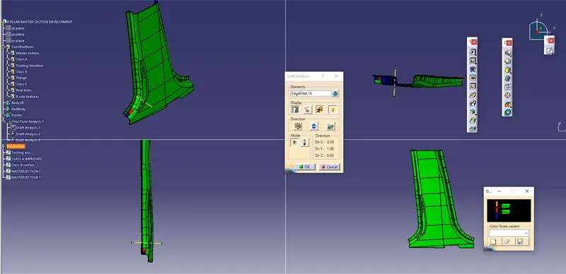
so in the above result, u can see that the draft provided to the B pillar is 3 degrees and for the ribs locator and dog house the draft is 0.5 degrees.
CONCLUSION - This concludes the creation of the B pillar solid part using the class A surface along with Engineering features and the draft analysis on the component.