Week 9-Creation of 1D Connectors Challenge
AIM - To create the 1 D connectors on the given geometry to attach the parts of the geometry using HyperMesh.
OBJECTIVE - To mesh the given geometry following the below-mentioned quality criteria:
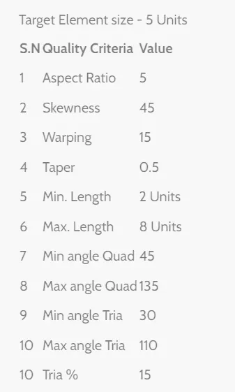
To create connectors and attach the various parts of given model.
1. Right_Rail_2 & Front_truss_1:- Seam-Quad(angled+capped+L)
2. Left_Rail_2 & Front_truss_1:- Quad elements
3. Front_truss_2, Front_truss_1 & Right_Rail_1:- Spot weld with 2 Layers and 5 mm Diameter
4. Front_truss_2, Front_truss_1 & Left_Rail_1:- Hexa (Adhesive)
5. Rear_truss_2 & Right_Rail_2:- Bolt Connector
6. Rear_truss_2 & Left_Rail_2:- Bolt Connector
7. Right_Rail_1 & Right_Rail_2:- Spot-weld with Rigid Elements
8. Left_Rail_1 & Left_Rail_2:- Spot-weld with Spring Elements
9. Rest all the component left Join them with suitable connectors
THEORY - Connectors - connectors allow us to create relationships between two nodes in an FEA model when we discretize a complex CAD model. The connection can be simply made by using rigid or some of them will be weld or bolt connections, which can impose more complicated constraints.
The reasons for using connectors are: connectors ensure the connectivity between parts in a model. To represent the geometric connection in terms of FEA. And finally to transmit the force between the parts which are connected together.
Connection in HyperMesh:
In HyperMesh, connections can be created as a spot-weld, seam weld, adhesive, bolts, and masses. A realized connector will be considered as the successful representation of a CAD model in the preprocessing stage. Then it will be moved into the solver side. The input for the creation of the connector will be extracted from the CAD model or from the design data.
some commonly used connectors are as follows:
Seam Weld - The process of joining the workpiece which is made of similar or dissimilar materials along a continuous seam is known as seam weld.
Spot weld - It is a resistance welding process that is used primarily for welding two or more metal sheets together by applying pressure and heat to the weld area. Heat for the welding process will be obtained from resistance to electric current.
Bolt connection - It is a type of connection between structural members made with plates and bolts, as opposed to a riveted or welded construction. In HyperMesh it uses the RBE2 elements to create a bolt connection.
Adhesive - Adhesive connection is also used to connect two parts of the model. This works similar to how an adhesive would work in real life.
PROCEDURE - The model given is the frame assembly model so I will start by importing the model. The model after importing is shown below:
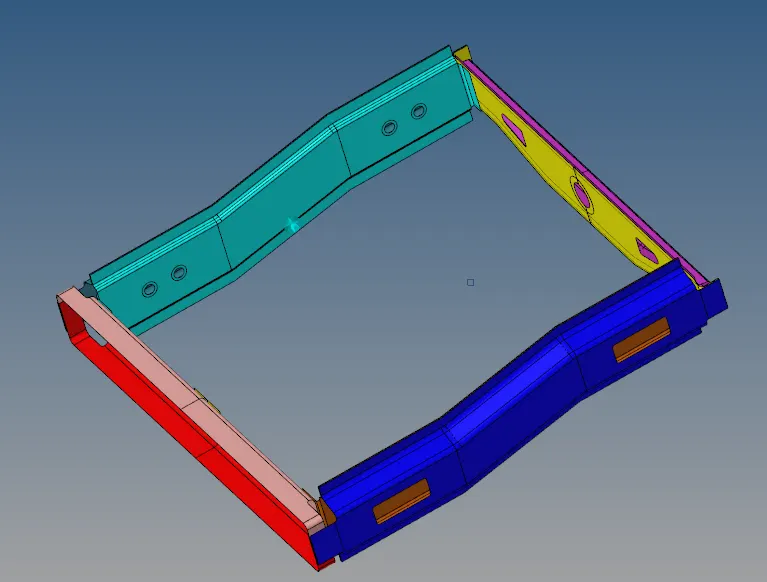
Now in the above-shown model, there is a total of 9 components. so I will mesh the individual component according to the quality criteria given. But before meshing I will set up the criteria file. The criteria file is shown below:
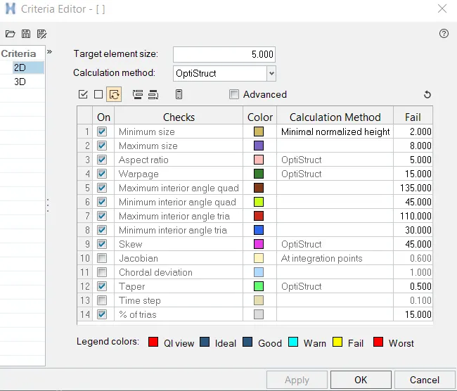
After setting up the criteria file. I will mesh the components so for that I will go to automesh under the 2 D and set the target element size as 5 units and mesh the components.
The mesh of the Front truss 1 is shown below:
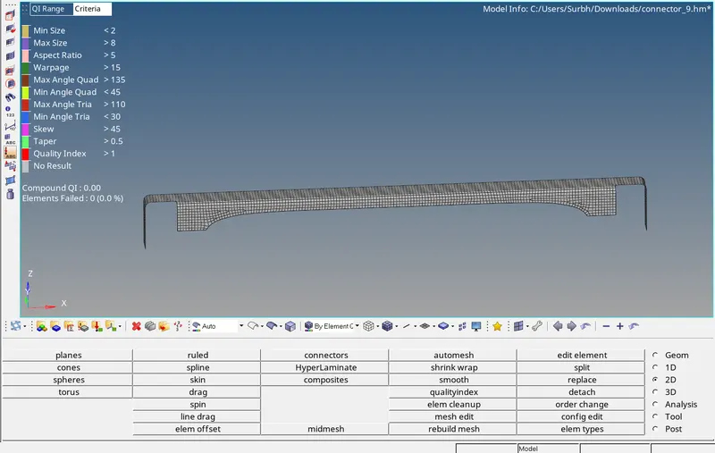
The mesh of the Front truss 2 is shown below:
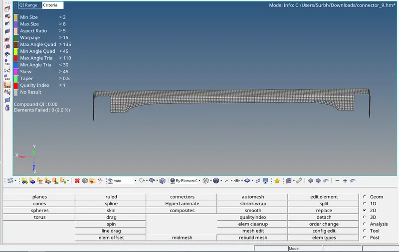
The mesh of the Reinforcement plate is shown below:
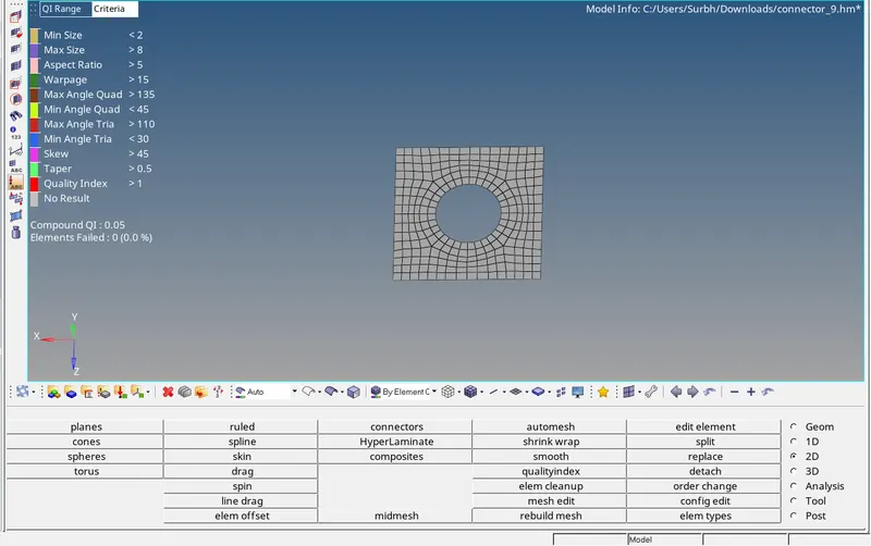
The mesh of Right rail 1 is shown below:
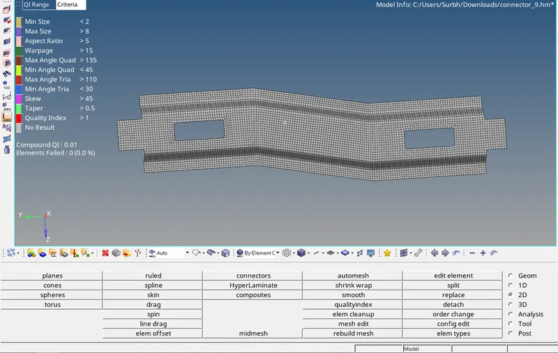
The mesh of Right rail 2 is shown below:
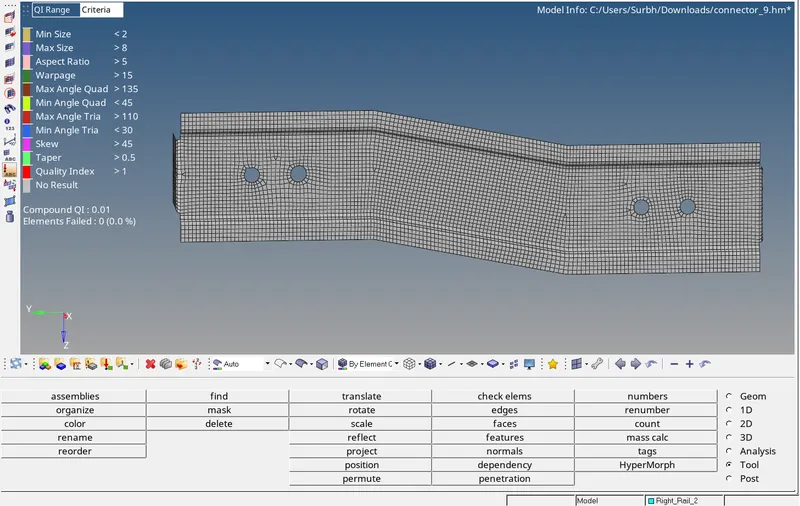
The mesh of the left rail 1 is shown below:
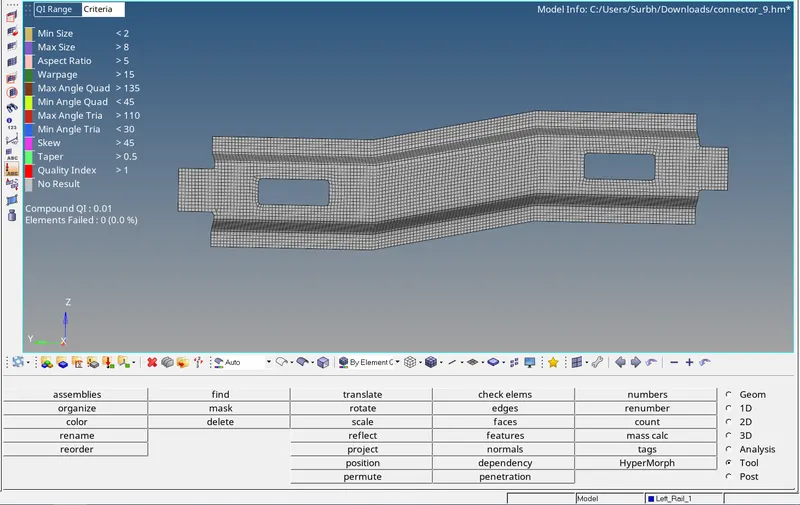
The mesh of Left Rail 2 is shown below:
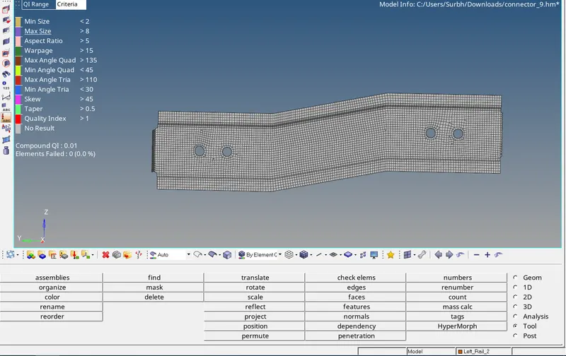
The mesh of Rear truss 1 is shown below:
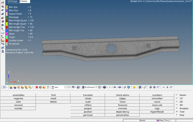
The mesh of Rear truss 2 is shown below:
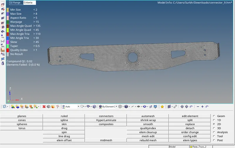
Now I will create the connections using the connector command under the 1 D section. The connections I have to create are:
1) Right_Rail_2 & Front_truss_1:- Seam-Quad(angled+capped+L)
To create the above-shown connection I will go to connectors under the 1 D menu and then go to seam and will select the nodes and specify the type as Seam-Quad(angled+capped+L) and also give the tolerance of 10 (as per the distance between two components) and spacing as 5 because it should be same as target element size, finally I will select the components in which I have to create the connection. The Seam-Quad(angled+capped+L) connection is shown below:
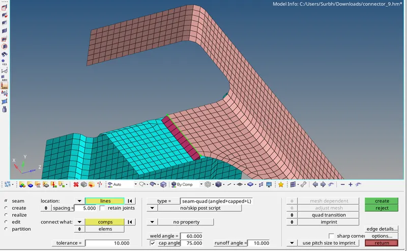
2) Left_Rail_2 & Front_truss_1:- Quad elements
To create the above-shown connection I will go to connectors under the 1 D menu and then go to seam and will select the nodes and specify the type as Seam-Quad and also give the tolerance of 10 (as per the distance between two components) and spacing as 5 because it should be same as target element size, finally I will select the components in which I have to create the connection. The seam quad connection is shown below:
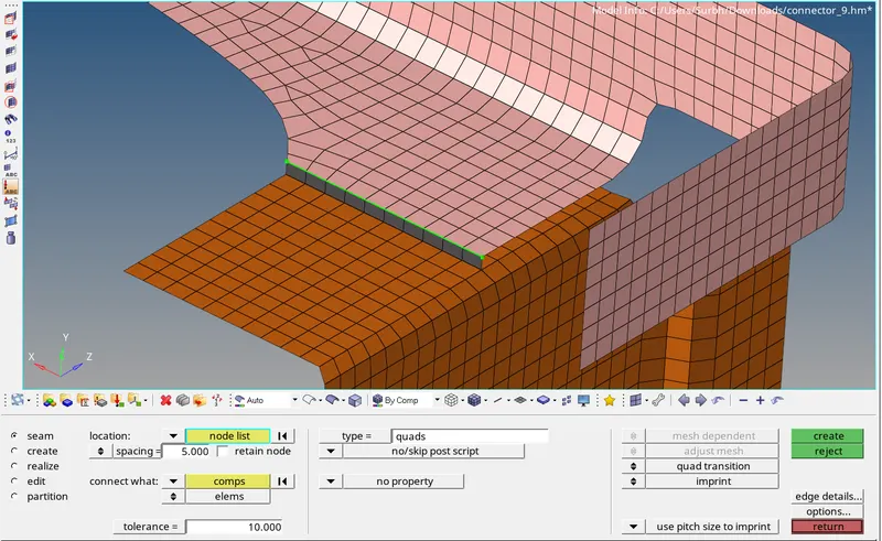
3) Front_truss_2, Front_truss_1 & Right_Rail_1:- Spot weld with 2 Layers and 5 mm Diameter
To create the above-shown connection I will go to connectors under the 1 D menu and then go to spot and will select the nodes and specify the type as weld and also give the tolerance of 10 (as per the distance between two components) and give the diameter as 5 because it should be same as target element size, and specify the layer as 2 then finally I will select the components in which I have to create the connection. The spot weld connection is shown below:
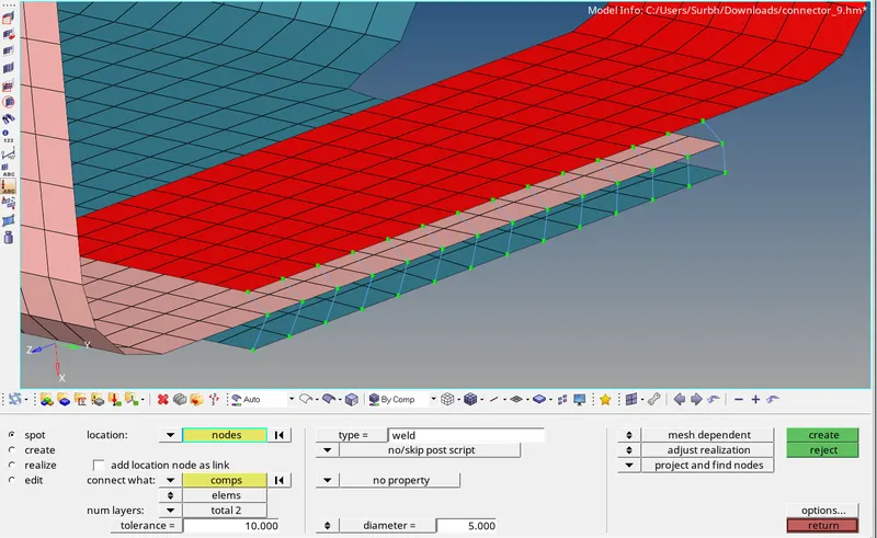
4) Front_truss_2, Front_truss_1 & Left_Rail_1:- Hexa (Adhesive)
To create the above-shown connection I will go to connectors under the 1 D menu and then go to seam and will select the nodes and specify the type as Hexa(Adhesive) and also give the tolerance of 10 (as per the distance between two components) and spacing as 5 because it should be same as target element size, finally I will select the components in which I have to create the connection. The Hexa(Adhesive) connection is shown below:
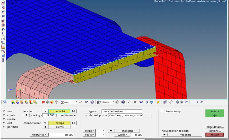
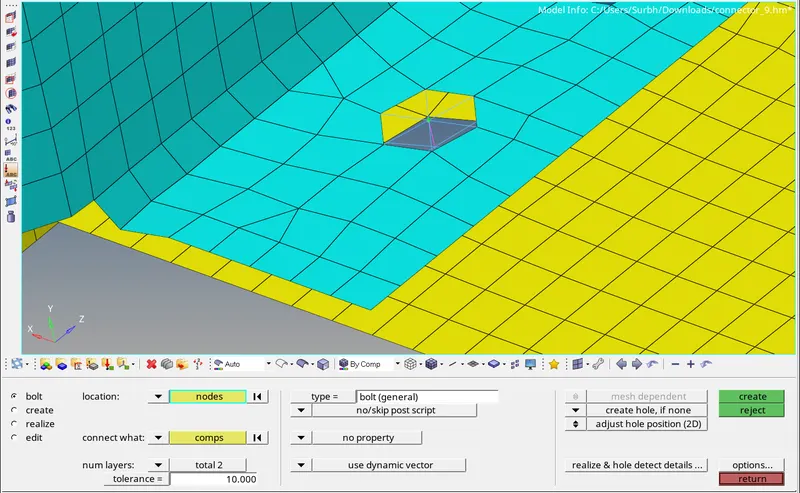
5) Rear_truss_2 & Right_Rail_2:- Bolt Connector
To create the above-shown connection I will go to connectors under the 1 D menu and then go to bolt and will select the nodes and specify the type as general and if there is no existing hole in the model click on the create hole, if none command. specify the tolerance as 10 (as per the distance between two components) finally, I will select the components in which I have to create the connection. The bolt connection is shown below:
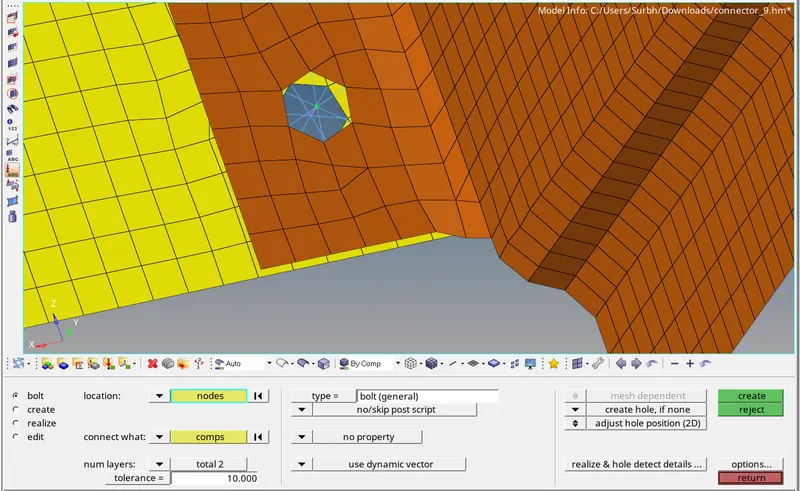
6) Rear_truss_2 & Left_Rail_2:- Bolt Connector
To create the above-shown connection I will go to connectors under the 1 D menu and then go to bolt and will select the nodes and specify the type as general and if there is no existing hole in the model click on the create hole, if none command. specify the tolerance as 10 (as per the distance between two components) finally, I will select the components in which I have to create the connection. The bolt connection is shown below:
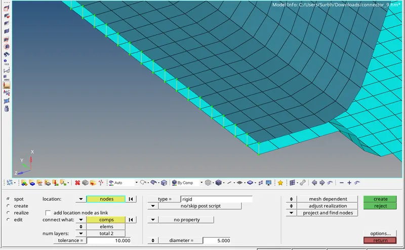
7) Right_Rail_1 & Right_Rail_2:- Spot-weld with Rigid Elements
To create the above-shown connection I will go to connectors under the 1 D menu and then go to spot and will select the nodes and specify the type as rigid and also give the tolerance of 10 (as per the distance between two components) and give the diameter as 5 because it should be same as target element size, and specify the layer as 2 then finally I will select the components in which I have to create the connection. The connection should be mesh dependent and it should not affect the mesh. The connection is shown below:
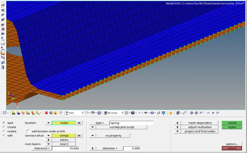
8) Left_Rail_1 & Left_Rail_2:- Spot-weld with Spring Elements
To create the above-shown connection I will go to connectors under the 1 D menu and then go to spot and will select the nodes and specify the type as spring and also give the tolerance of 10 (as per the distance between two components) and give the diameter as 5 because it should be same as target element size, and specify the layer as 2 then finally I will select the components in which I have to create the connection. The connection should be mesh dependent and it should not affect the mesh. The connection is shown below:
9) Rest all the components are connected using suitable connection such as (seam weld with rigid and spring elements, seam weld with quad elements)
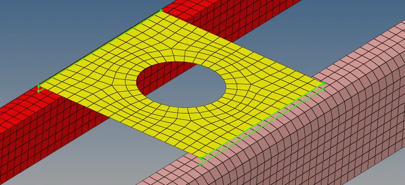
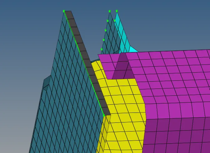
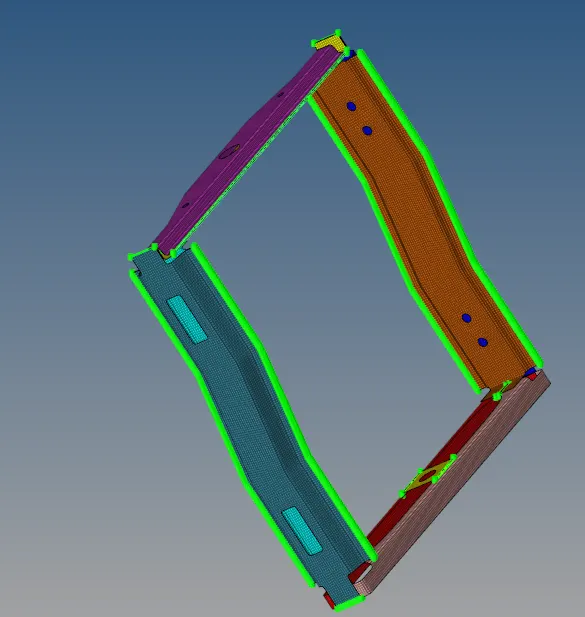
RESULT - All the components of the frame assembly model are attached and the final connections are shown below:
CONCLUSION - The creation of 1 D connectors on the given model of frame assembly has been completed successfully and the results are shown.