Design of backdoor
AIM - To design the Backdoor of the car using the appropriate design methodologies, providing the necessary Reinforcements and embosses.
INTRODUCTION - Back door is the rearmost part of a pick-up truck or SUV that opens downward and gives access to the vehicle's cargo area. The backdoor of hatchbacks or SUVs is connected to the roof whereas in the sedan case, the backdoor is hinged below the rear window. Like the hood, the backdoor is also a swinging component consisting of the outer and inner panels. The backdoor of an SUV is shown below:
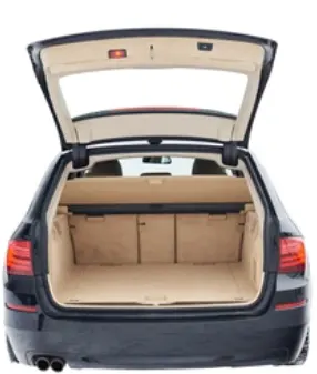
The trunk or luggage compartment is most often located at the rear of the vehicle. Early designs included an exterior rack mounted on the rear of the vehicle to which it was possible to attach a real luggage trunk. Later designs integrated the storage area into the vehicle's body and evolved to provide a streamlined appearance. The main storage compartment is normally provided at the end of the vehicle opposite to which the engine is located.
Just like the hood here also gas stays are used to keep the backdoor in open condition. It just requires an initial thrust and then the gas itself actuates and works desirably. stud balls are generally used for connecting the gas stay
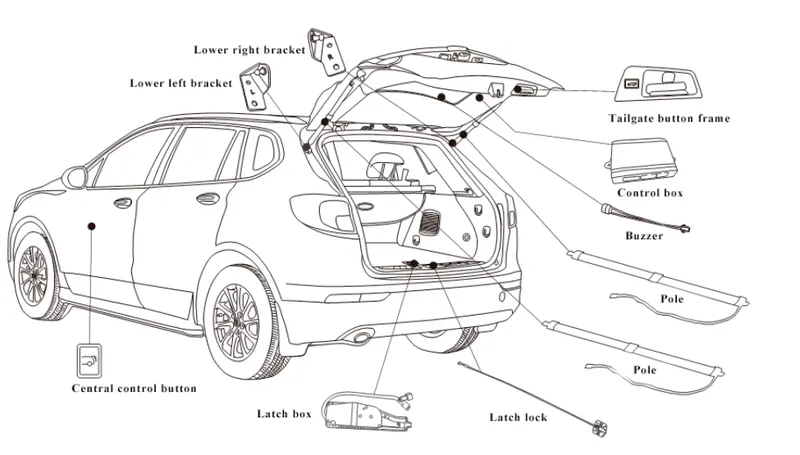
Here I will be designing the backdoor of a hatchback using the class A styling that is given to me. The Backdoor has to be designed by keeping in mind the luggage space required as well as the space to accommodate all the reinforcements( viper, hinge, latch, and gas stay) without compromising on the strength.
The materials that are used to manufacture the backdoor are usually steel and aluminum. For the aluminum, the reinforcements are not required because they are formed using the casting but for the steel, backdoor reinforcements are needed because they are deep-drawn.
so here I will be creating the outer and inner panels of the backdoor along with the necessary reinforcements (viper, latch, hinge, and gas stay)
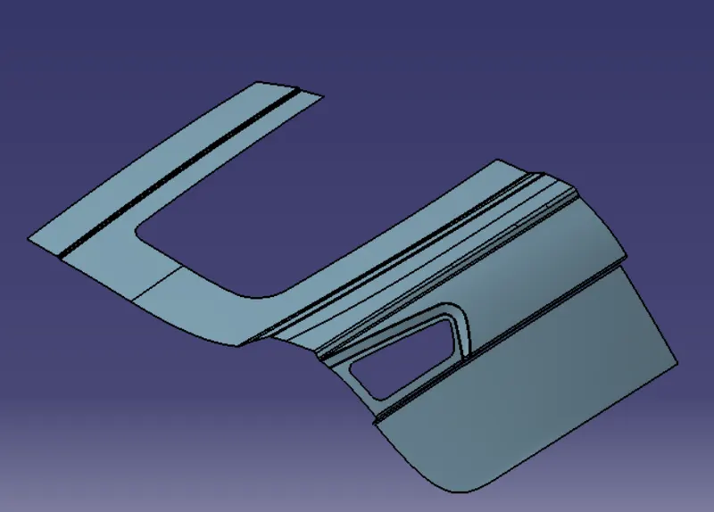
PROCEDURE - The class A surface given to me is shown below:
outer panel:
Using the above-shown class A surface I will be first designing the outer panel of the backdoor. Here I will be diving the outer panel into two parts first the upper outer panel and the other lower outer panel.
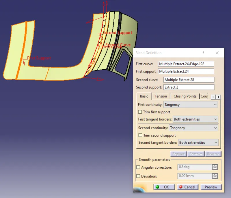
Here the class A given is not correct and it has some errors so I have first modified the class A surface so basically for modifications I have used the multisection section feature and blend to connect the surfaces which were creating an issue for the joining. some of the corrections I have made are shown below:
Then I have given the fillets to some areas as well
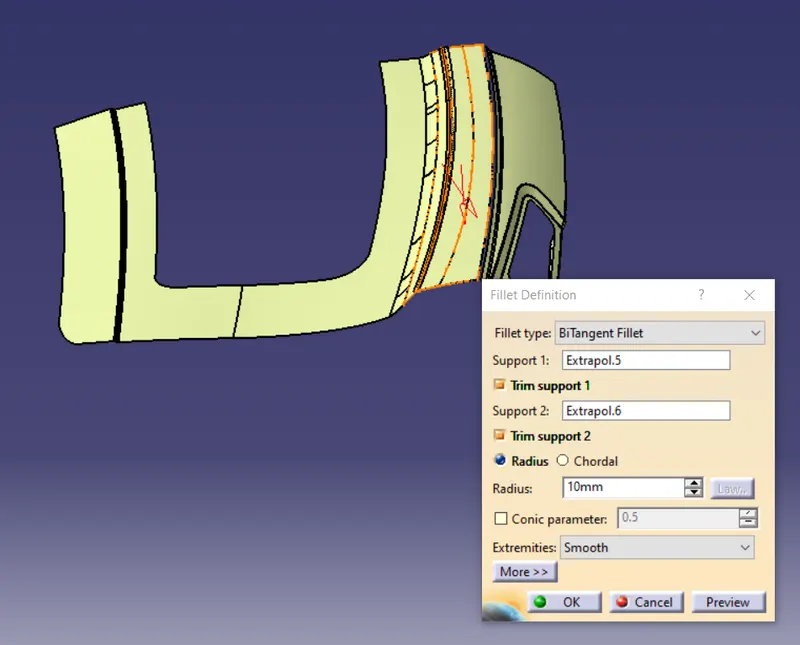
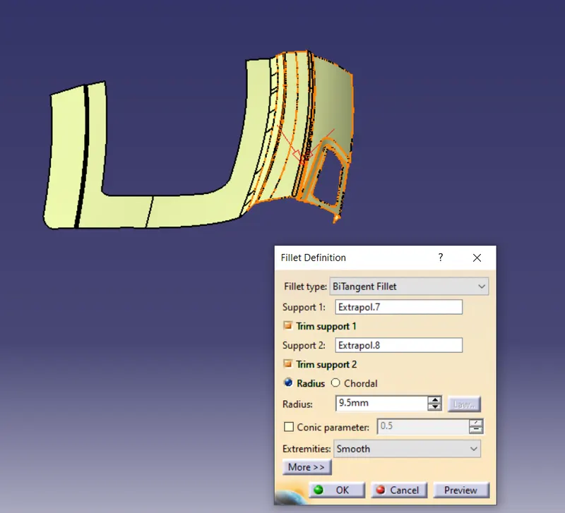
Here the critical area is the tail lamp area so there also I have given the fillets to make sure
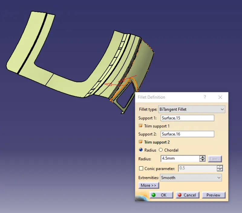
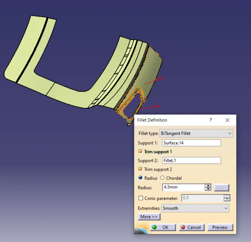
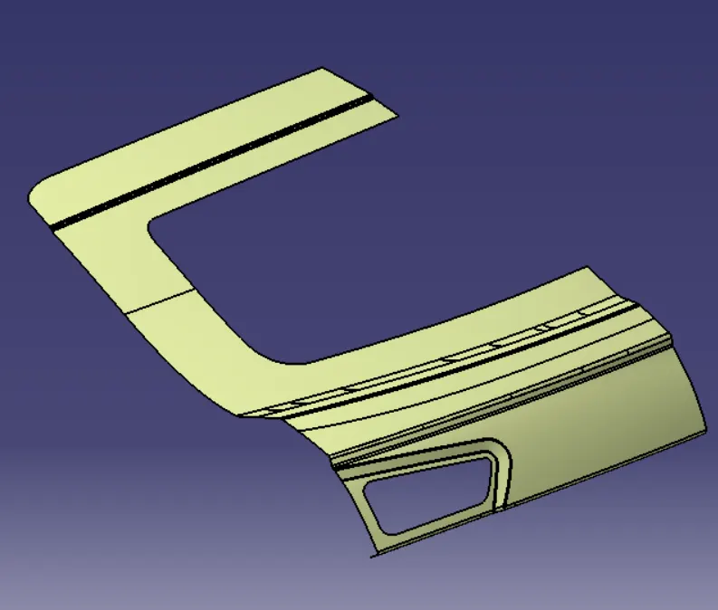
The final outer upper panel is shown below:
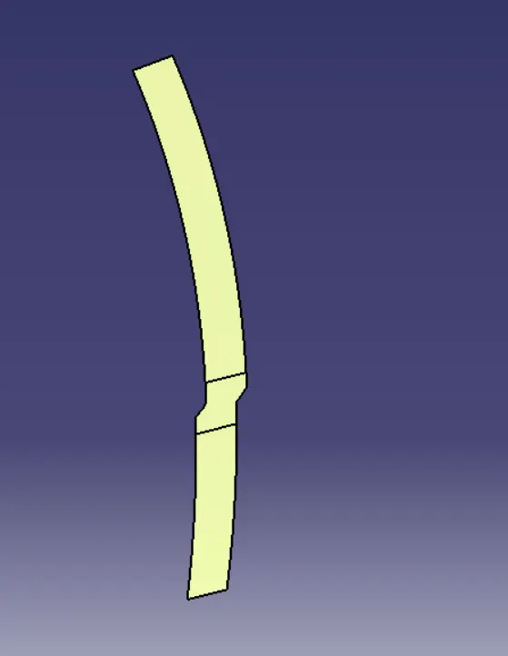
Now for creating the outer lower panel I will extract the base which is shown below:
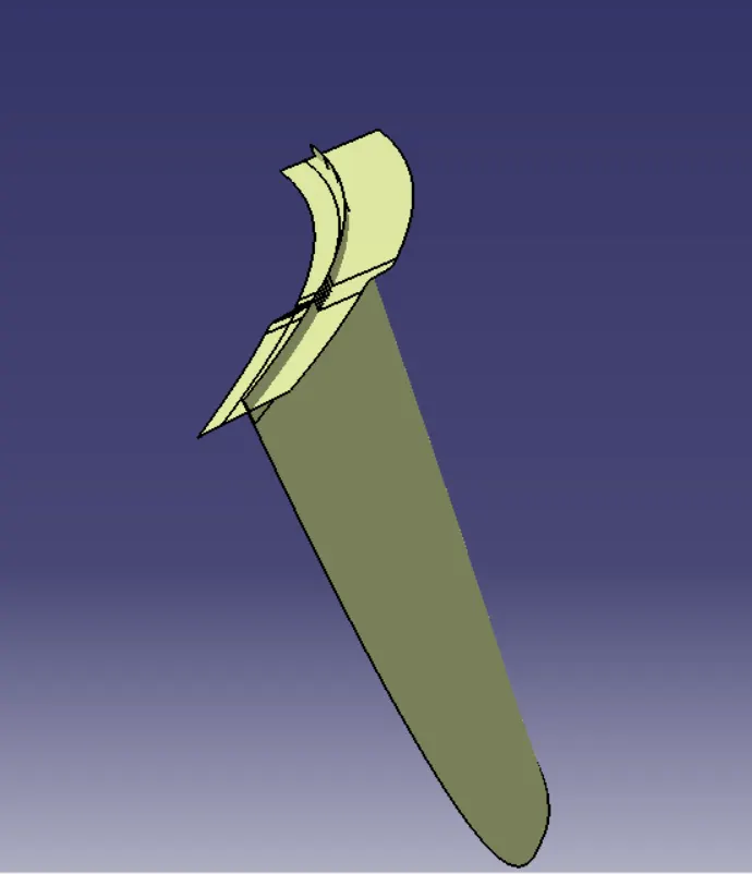
Now I will extrapolate this surface to a certain distance and I will also extrapolate the lower outer surface. The extrapolated surfaces are shown below:
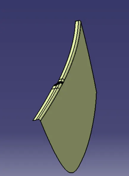
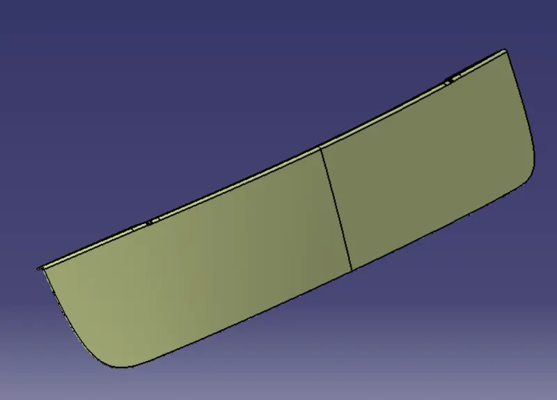
Then I will just provide the shape fillet to get the lower outer panel for the backdoor. The lower outer panel is shown below:
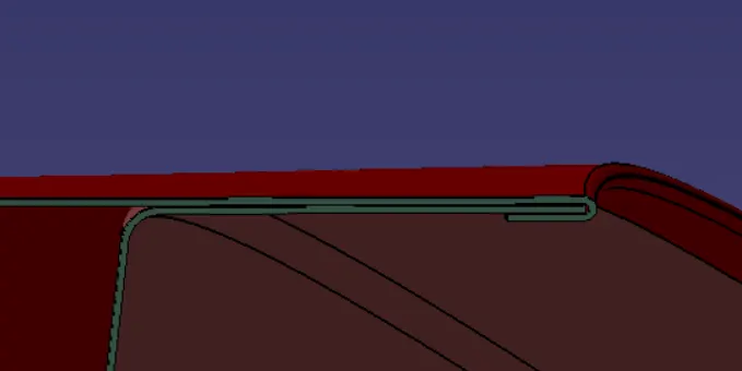
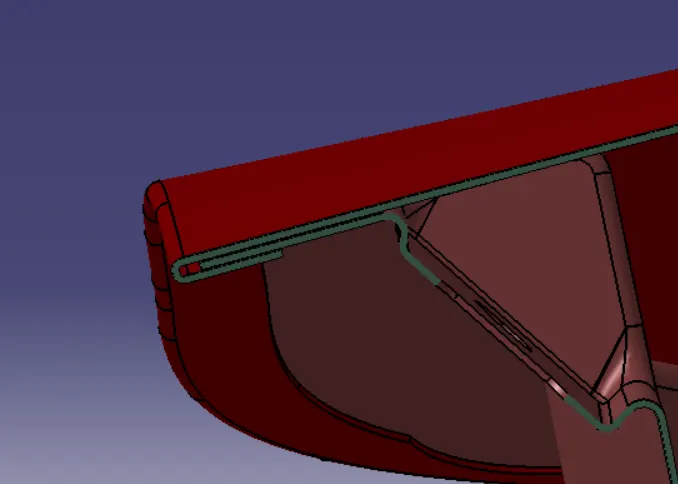
Now I will create the hemming for both the upper and lower outer panel because the outer panel will be joined with the inner panel using the hemming process.
Hemming is a forming operation in which the edges of the sheet are folded or folded over another part in order to achieve a tight fit. Normally hemming operations are used to connect parts together, to improve the appearance of a part, and to reinforce part edges.
In car part production, hemming is used in assembly as a secondary operation after deep drawing, trimming, and flanging operations to join two sheet metal parts (outer and inner) together. Typical parts for this type of assembly are hoods, doors, trunk lids, and fenders. The accuracy of the hemming operation is very important since it affects the appearance of the surface and surface quality.
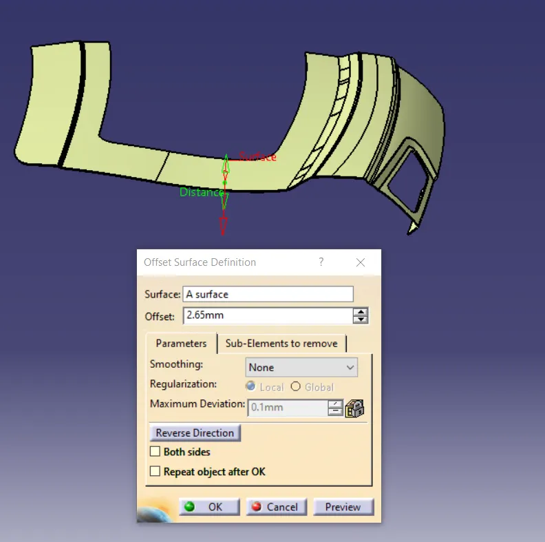
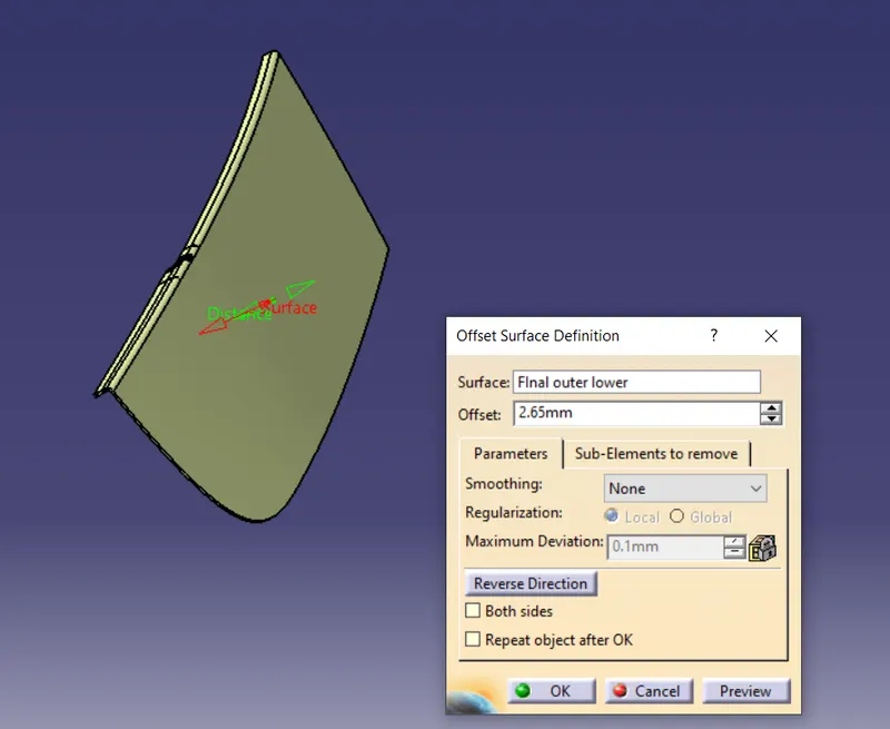
For creating the hemming I will first offset the upper outer panel surface to 2.65 mm considering the thickness of both upper and inner panels and the gap of 0.2 mm to maintain between the panels.
The offset is shown below:
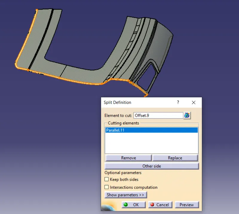
Then in the offset created I will take the boundary of the portion in which hemming will be done and offset that portion to 10mm and split it. The split is shown below:
Now I will take the boundaries of both the split surface and the A surface and I will blend. The blend is shown below:
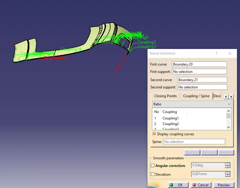
here in the above blend, you can see that I have used the coupling to make sure that the blend is in perfect shape because if I would have not done that it would have created some problems in later stages while using the fillets.
Then again I have modified the blend to remove the sharp edges to make the blend smooth. The modifications that I did was I have offset the sharp edges to say 0.5 or 1mm on both sides and split it and again blend the splits giving supports. Here the main aim should be that the blend has to be smooth. After doing multi splits and then joining them together I got my final blend. The final smooth blend is shown below:
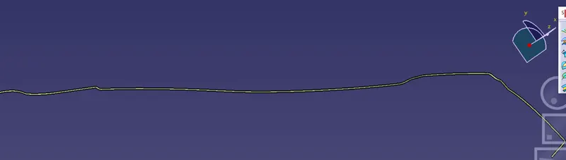
Then I will just give the fillets to make the hemming. The hemming of the upper outer panel is shown below:
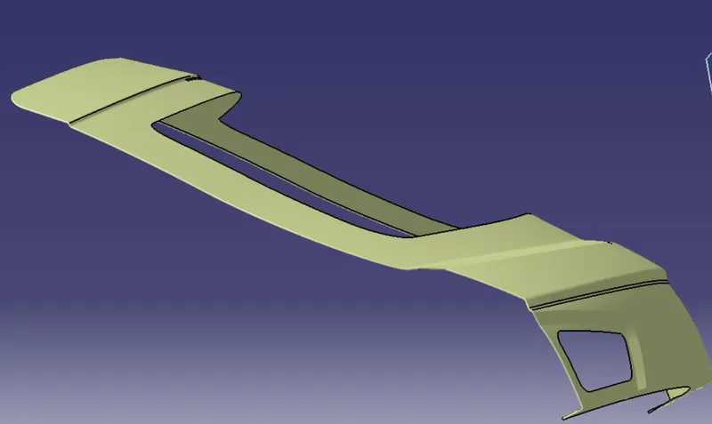
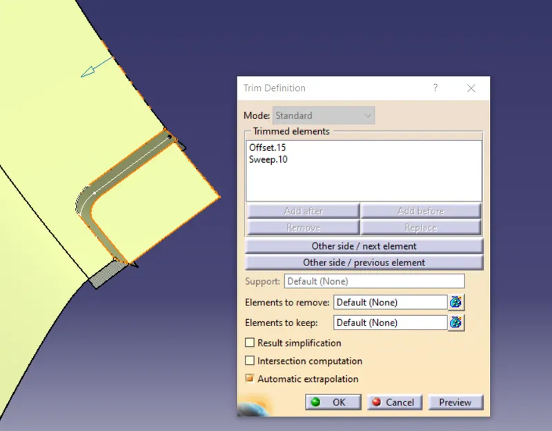
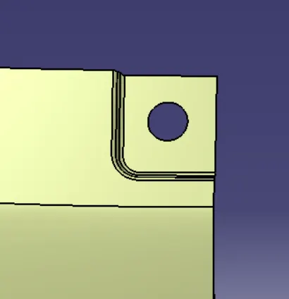
Here I will provide the reliefs as well for the hemming. Reliefs are provided to prevent unwanted damages to the surface. So basically these reliefs are provided on the corners to avoid intolerance issues arising from the rolling process. For providing the reliefs I will create one curve at the corner and then split it from the outer upper panel. The Relief is shown below:
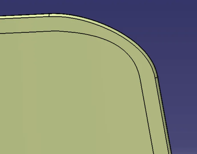
Then I will just mirror the surface to get the final upper outer panel of the backdoor. The outer upper panel is shown below:
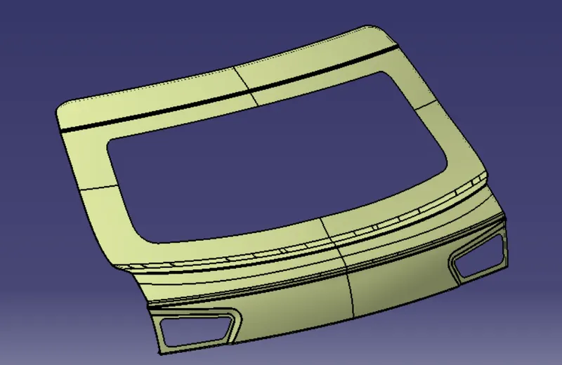
Now I will create the hemming for the outer lower panel. So again I will follow the same procedure I will offset the surface to 2.65 mm and then take the boundary where the hemming will be done and offset it to 10 mm and split it.
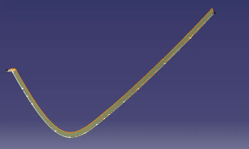
Then again I will the boundaries of the split and the A surface and then I will make one curve connecting both the split and the A surface. The connect curve is shown below:
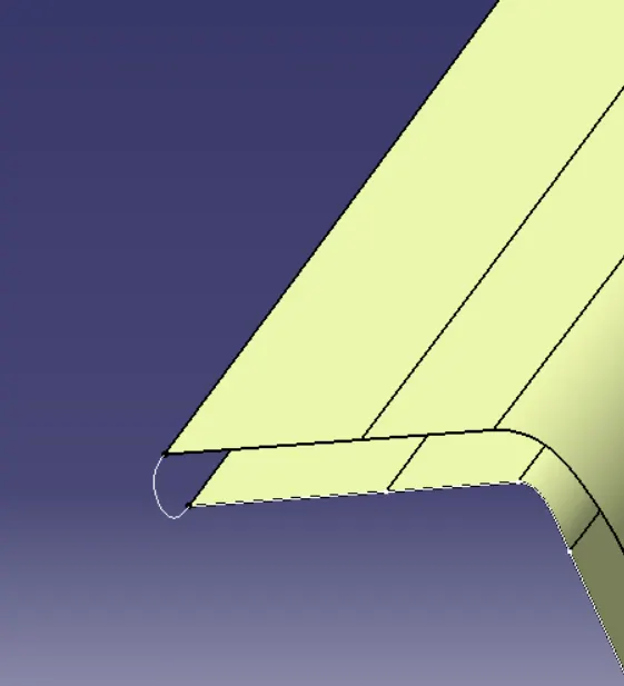
Then I will just sweep using two guide curve option The sweep is shown below:
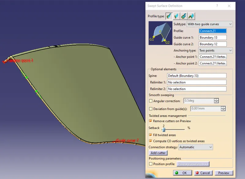
Then I will just join to get the hemmed lower outer panel of the backdoor. Here also the reliefs will be provided. The relief is shown below:
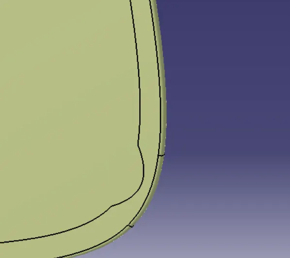
Then again to get the complete lower outer panel I will again mirror the surface. The lower outer panel is shown below:
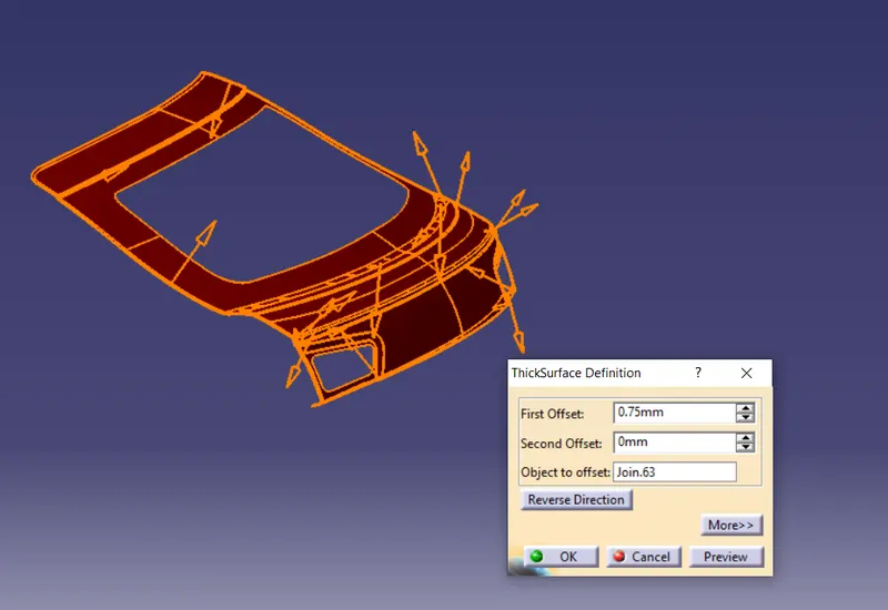
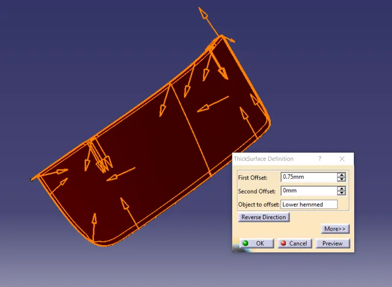
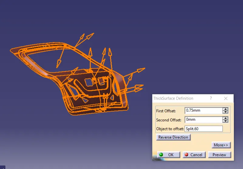
To create the solid parts I will just thicken both the upper and lower outer panels. Here the thickness of the outer panel will be 0.75 mm and the direction will be downwards.
The Outer panel of the backdoor is shown below:
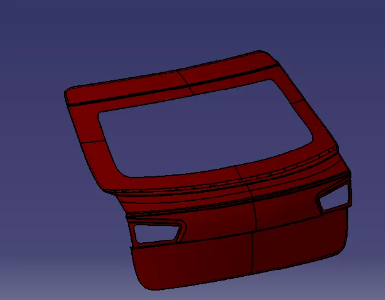
Now the outer panel is ready and I will next create the inner panel of the backdoor
Inner panel: Before creating the inner panel I will first create the tooling axis. The tooling axis is defined as the direction in which the mold opens or core and cavity opens and closes. The selection of the correct tooling axis is important to ensure the component is taken out perfectly and also the cost of the component should be less. The draft on the inner panel is provided using that tooling axis
For creating the tooling I will just make one sketch. The sketch is shown below:
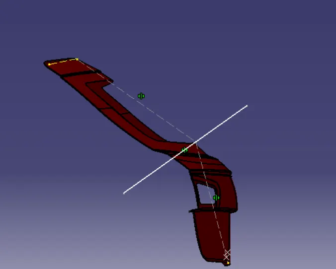
The tooling axis is shown below:
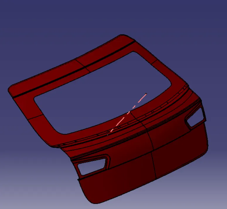
Now I will create the sealing flange
For creating the sealing flange I will offset the A surface of the outer panel to 1.7 mm considering the thickness of the outer and inner panel and the gap of 0.2 mm in between. The offset is shown below:
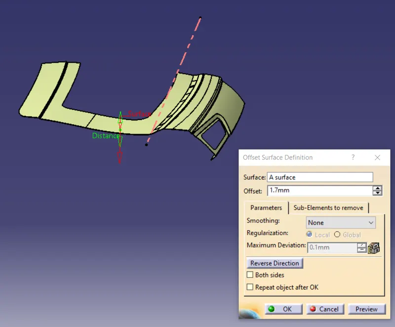
Then again I will extract the surfaces and offset them to 25 mm. The offset surfaces are shown below:
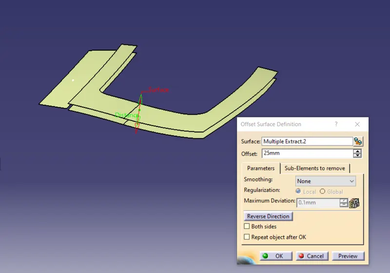
Then I will offset the edges using the parallel curve feature and split it
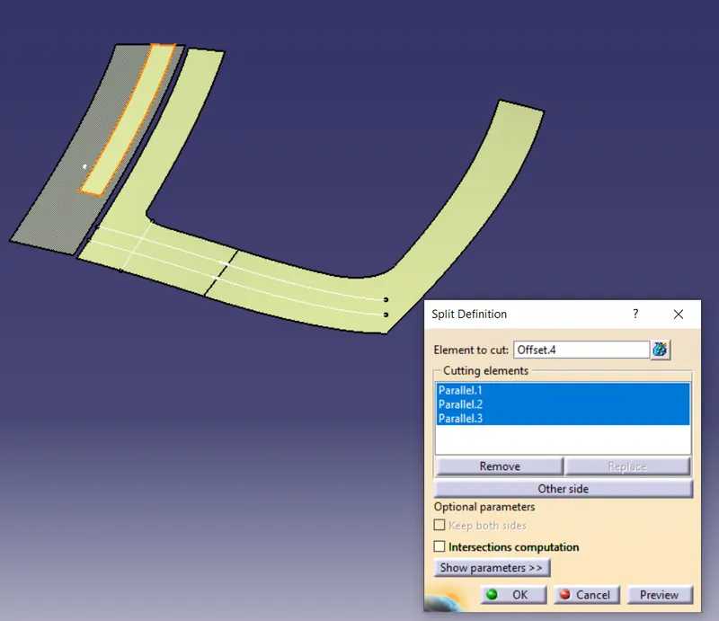
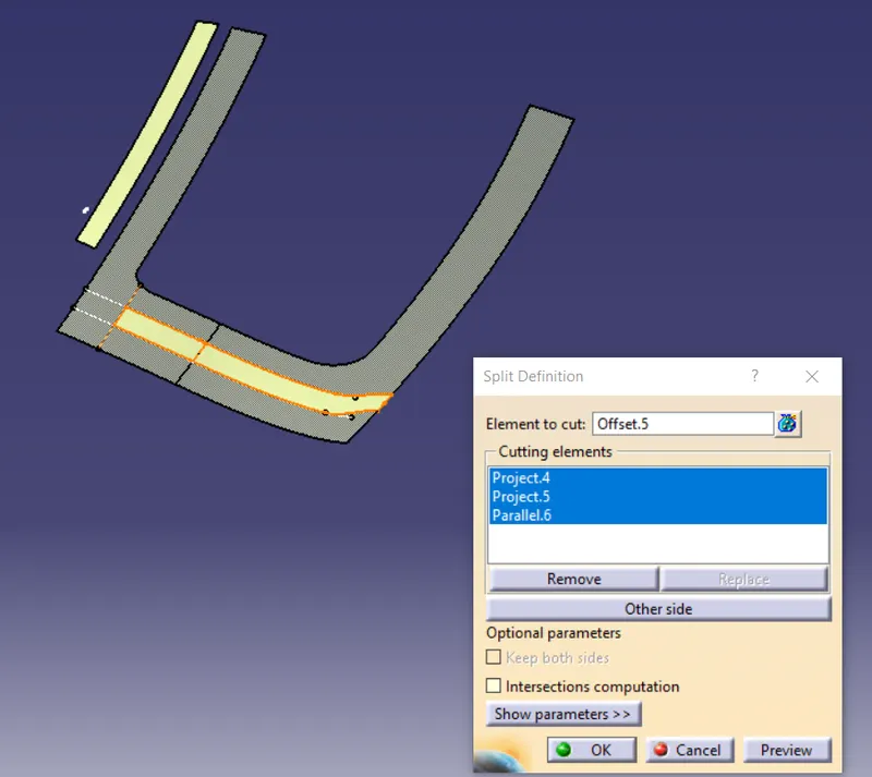
Then again I will extract the surface around the tail lamp area and I will untrim and offset it through a certain distance and then again offset the edges using the parallel feature and split it
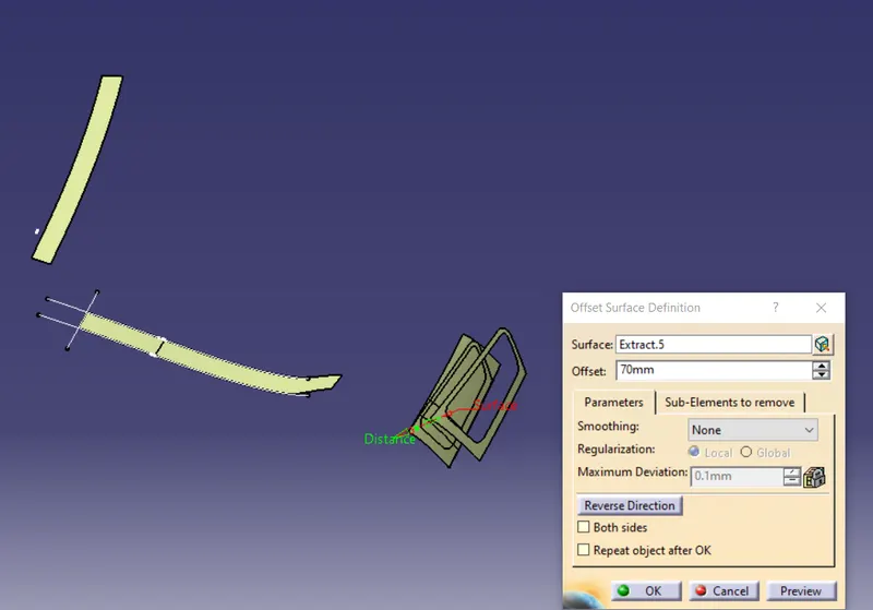
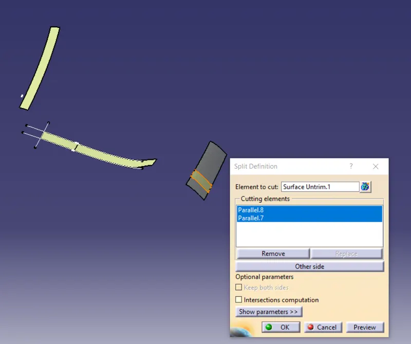
Then again I will extract the surface from the lower outer panel and offset the edges and split it
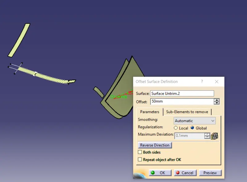
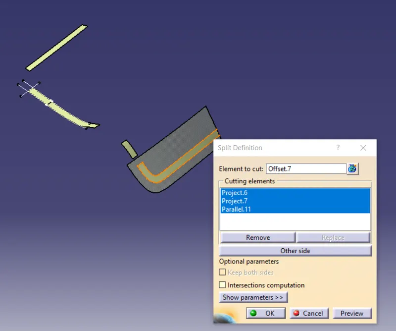
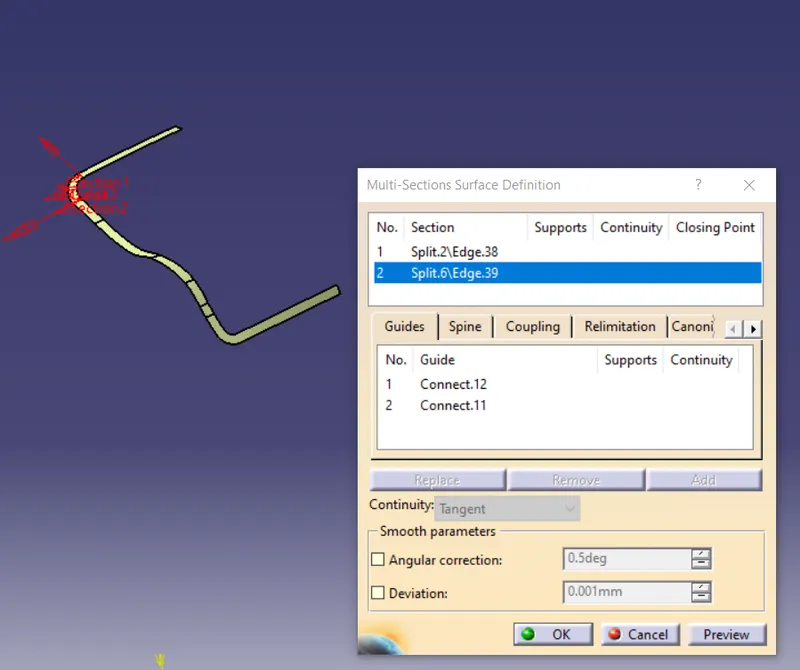
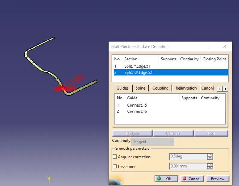
Then to complete the sealing flange I will use the multisection feature to join and will connect the surface to make a single surface. So I will create the guides for multisection using the connect curve feature and will do the multisection.
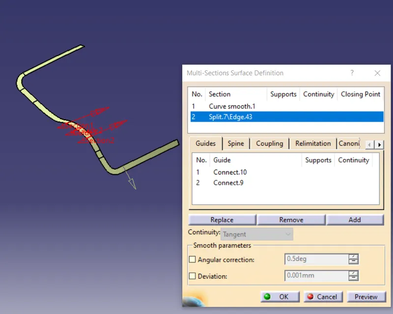
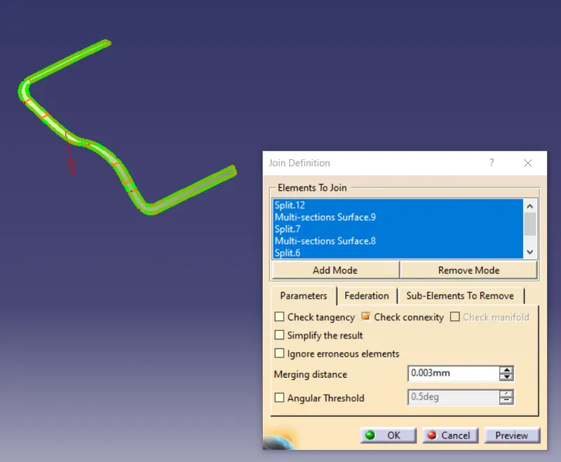
Then finally I will join all the surfaces to get the flange. The join is shown below:
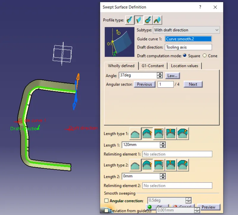
Now the sealing flange is completed and now will sweep the edges of the sealing flange along the tooling direction giving a draft of 7 degrees.
Then I will join the sweep with the flange and will give the fillet. The filleted flange is shown below:
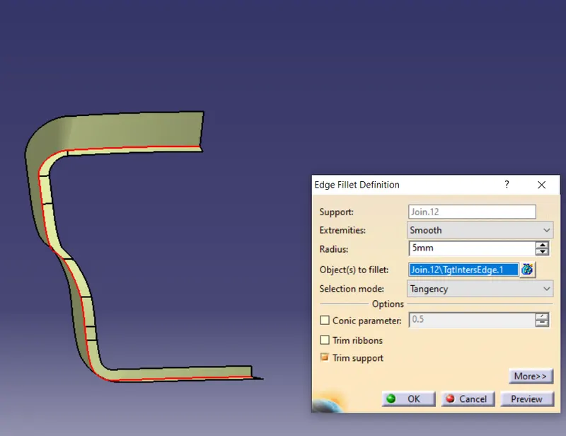
Then I will just trim this portion with the offset that I have created for the upper and lower outer panel of 1.7 mm.
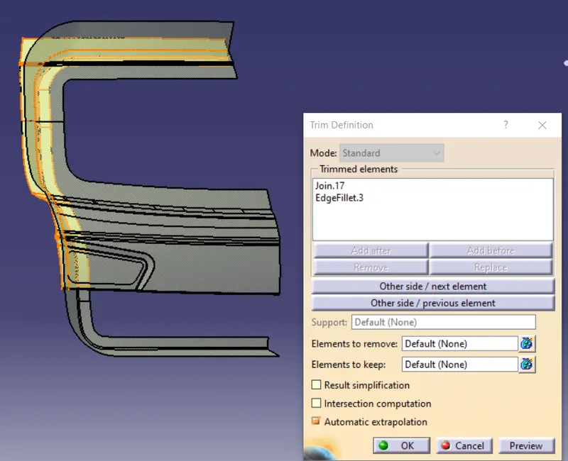
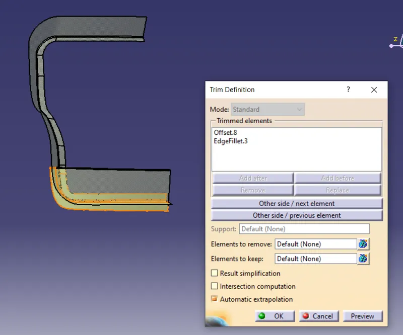
Now I will connect the upper and lower part because in the inner panel these two parts will be connected together so to connect them I will use the multisection and then provide the fillets
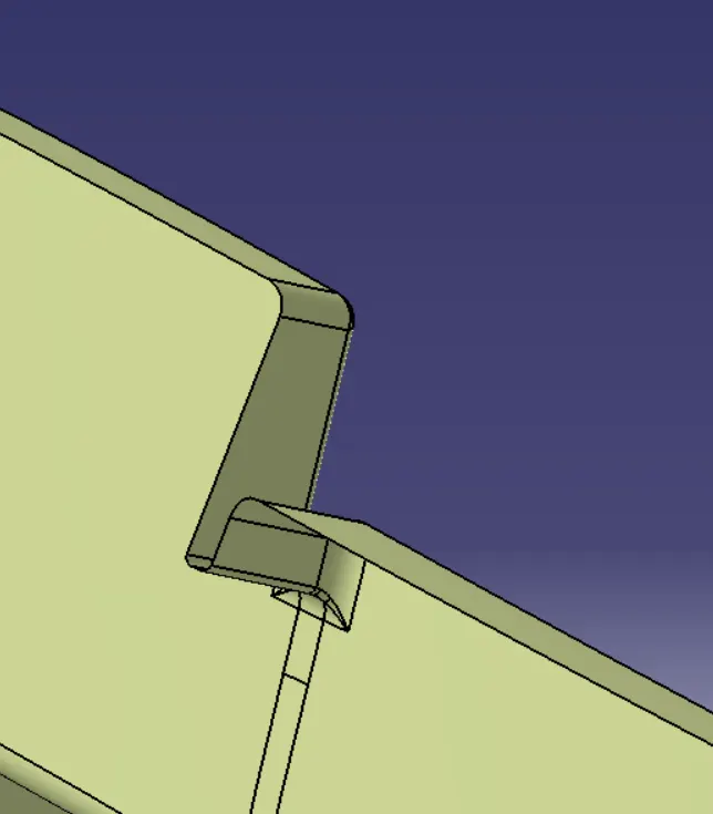
Now I will create the windshield area of the inner panel. For creating that I will first extract the surface and extrapolate that surface to intersect with the sealing flange and sweep the edge of the sealing flange.
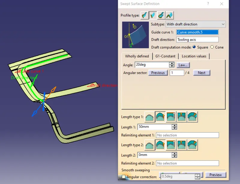
Then I will just split the swept surface from the extrapolated surface
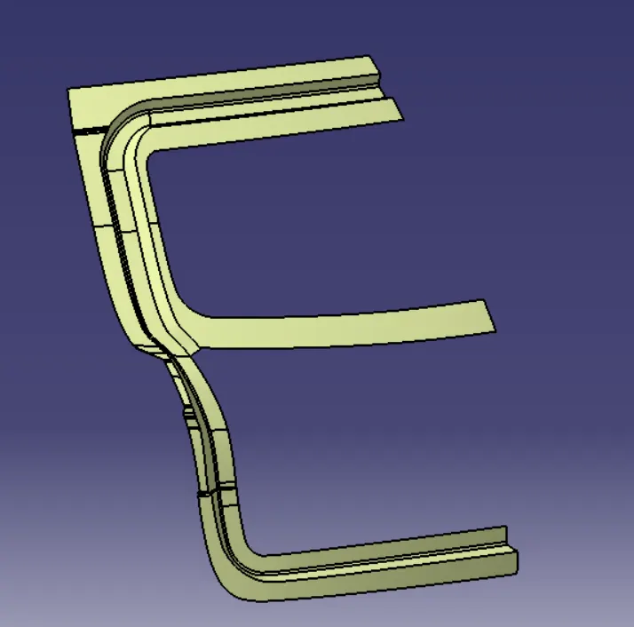
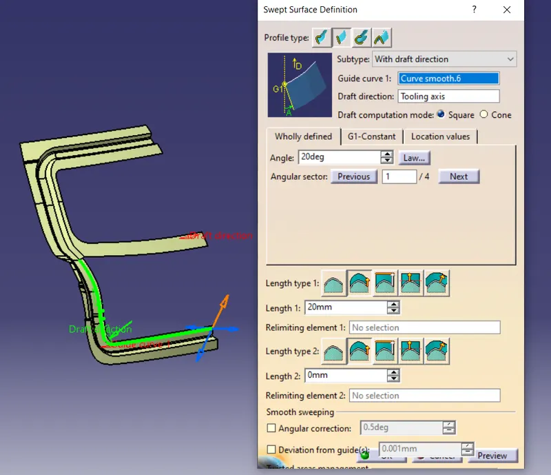
A similar thing I will do for the lower surface also
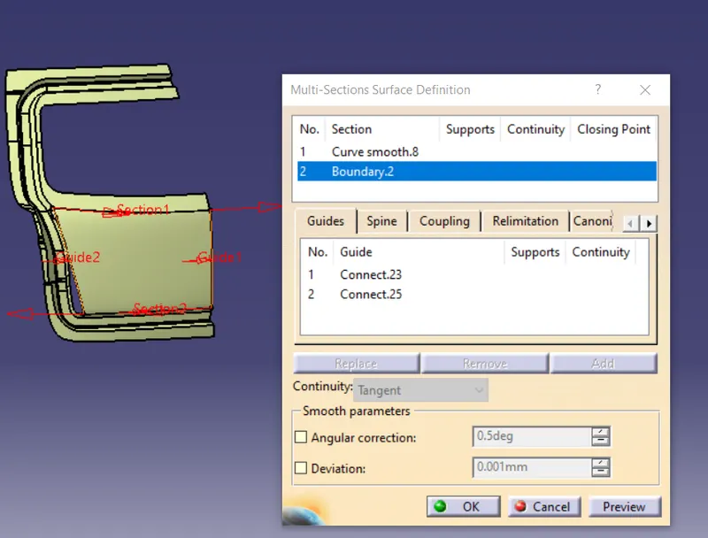
Then I will do the multisection surface to join create the lower surface for the windshield area. The guides for the multisection will be the connect curves that I will create. while creating the connect curves it is important to give the correct tangency so that the height should be proper. The multisection is shown below:
Then I will just extrapolate the multisection surface and the lower portion of the sweep and will trim to get the lower surface without any gaps and then finally I will join all the surfaces. The join is shown below:
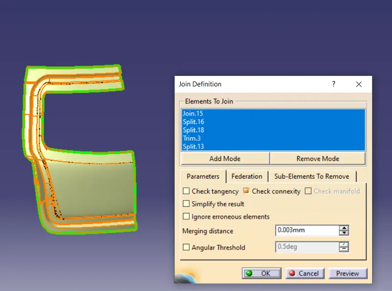
Now I will create the mastic region. Mastic sealants help to reduce the noise and vibrations and it does not affect the aesthetics of the car. They are used as a paste for joining the inner and outer panels and it also improves the strength.
For creating the mastic region I will just create one sketch and project it on the inner panel and then split the projected sketch to get the cutout.
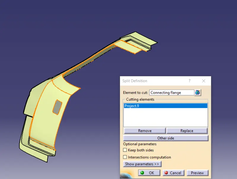
Then I will extract the surfaces from the styling which surrounds the mastic region and offset it to 5mm because there will be a 5 mm gap between the inner and outer panel for the mastic sealants.
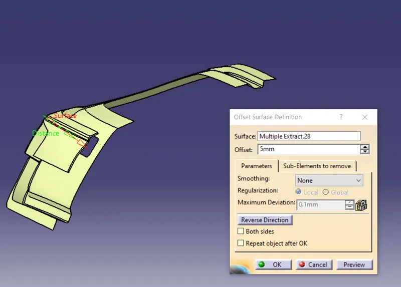
Then I will sweep one edge of the cutout that I created and provide the shape fillet
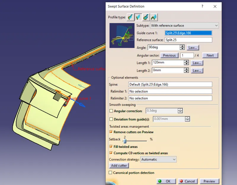
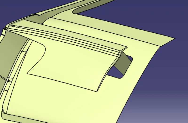
Then I will offset the edges and split them to get the required size of the mastic region and will provide the shape fillets to join it with the inner panel
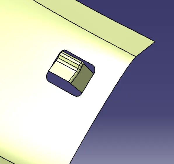
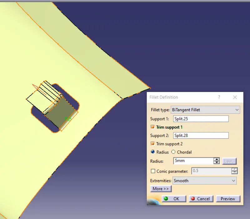
Now I will provide the fillets to the edges of the inner panel that I forgot to fillet earlier
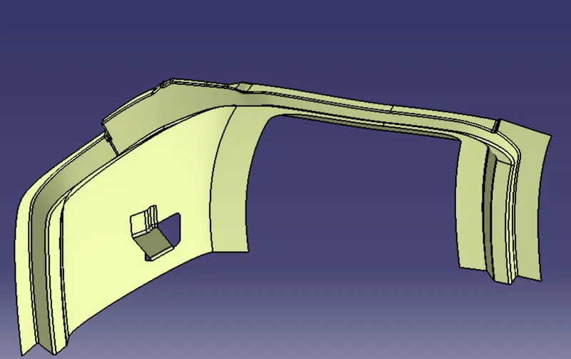
Here around that mastic region, I will provide the corner reliefs also. so for that, I will just create the splines and split them from the inner panel. The corner reliefs are shown below:
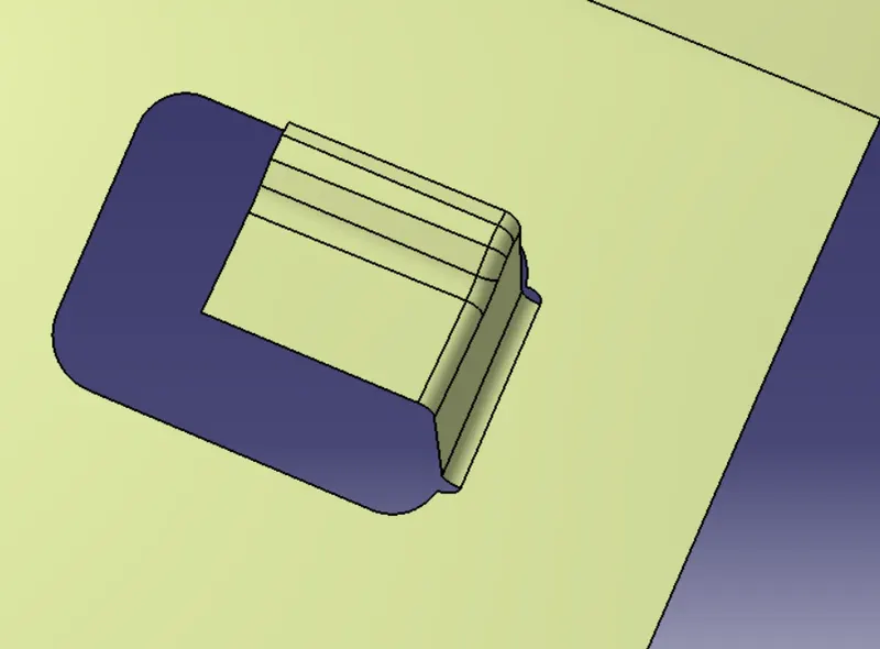
Embosses: Embosses help to increase the strength of the backdoor. The direction and design of the embosses should be to direct the forces away from the passengers to the outside of the vehicle so at the time of the collision the embosses absorb the impact of the collision and provides safety to the passengers. The embosses should be given in v And y shapes.
For creating the embosses I will create the sketch and project it on the inner panel and split it and sweep the edges of the cutout and trim it from the offset of the extracted surface then provide the fillets.
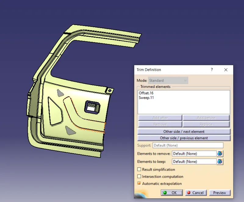
similar procedure I will follow to create more embosses and will provide some cutouts to decrease the weight of the inner panel but I will make sure that the cutouts are not sharp. The inner panel with embosses is shown below:
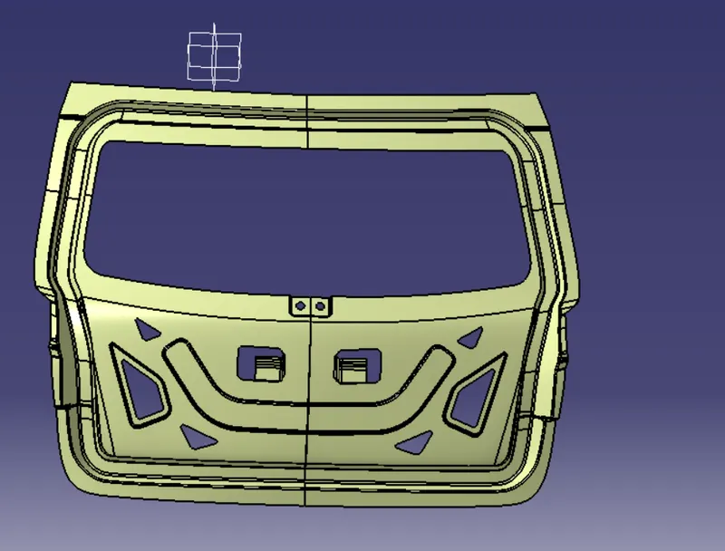
Now I will create the mounting points and Reinforcements
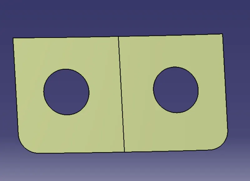
wiper Mounting - This mounting is created so that it can accommodate the viper on the backdoor. To create the wiper mounting I will follow the same procedure as I did for the embosses that is I will just create one sketch and project it on the inner panel, split and sweep and then trim it from the offset of the extracted surface.
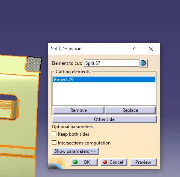
Then I will just provide the fillet and hole for fixing the wiper
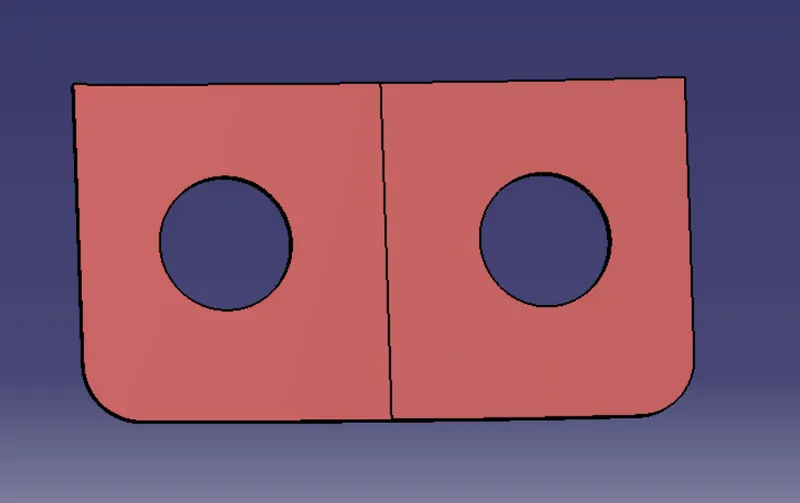
Wiper Reinforcement - Reinforcements are provided as it helps to increase the strength of the part. So for creating the reinforcement I will just extract the surfaces which surround the wiper mounting and split the extra part and will offset it to 0.75mm which is the thickness of the inner panel and I will thicken the extracted surfaces to 1mm and that thickened body will be my wiper reinforcement.
The wiper reinforcement is shown below:
Gas stay Mounting - Gas stay as mentioned earlier is the component that helps to keep the backdoor in open condition. one end of the gas stay will be connected to the backdoor and another end is connected to the body side. so for creating the mounting of gas stay I will again follow the same procedure as I did for embosses. First I will create one plane and will sketch on it, project, and split it from the inner panel
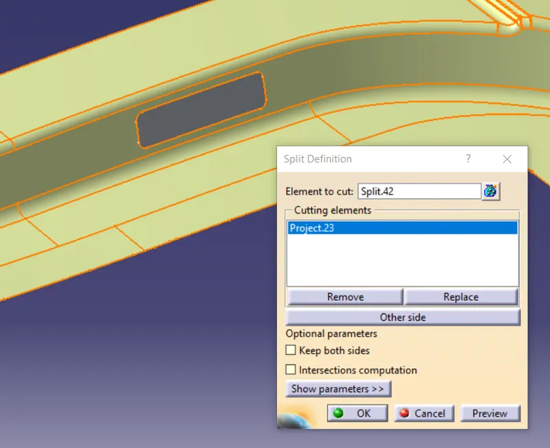
Then I will sweep it along the tooling direction giving a draft of more than 7 degrees. and will trim it from the offset of the extracted surface and then provide the fillets
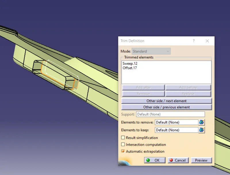
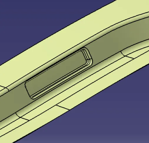
Then I will just provide holes for fitting. The gas stay mounting is shown below:
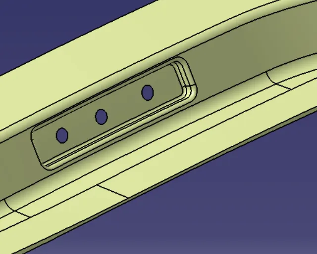
Gas stay Reinforcement - Based on the various simulation test like bend test, abuse test, and torsion test that pointed out that the gas stay area becomes weaker so the reinforcements are required to increase the strength of the backdoor.
For creating reinforcement I will again extract the mounting area and the surfaces near it and split the extra portion and offset to 0.75 mm.
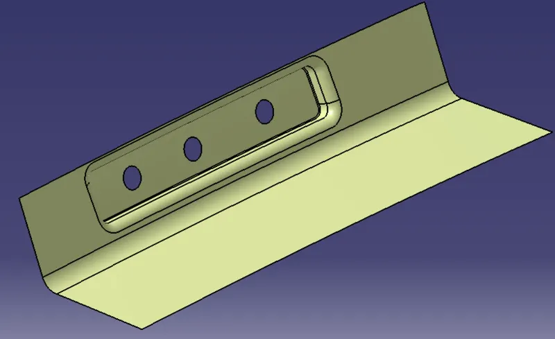
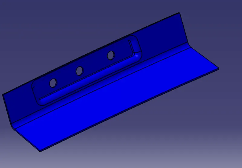
Then I will thicken the above-shown surface to 1mm and that will be the gas stay reinforcement. The fast stay reinforcement is shown below:
Hinge mounting - Hinge as mentioned earlier enables the opening and closing of the backdoor. one end of the hinge is fixed on the backdoor and the other end is fixed on the roof. For creating the hinge mounting I will create one plane and sketch on that plane, project it, and split it.
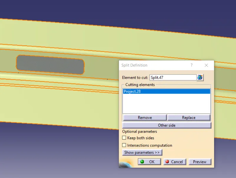
Then I will just sweep it along the tooling direction giving a draft of more than 7 degrees so as to make it manufacturable and then just trim it and provide the fillets
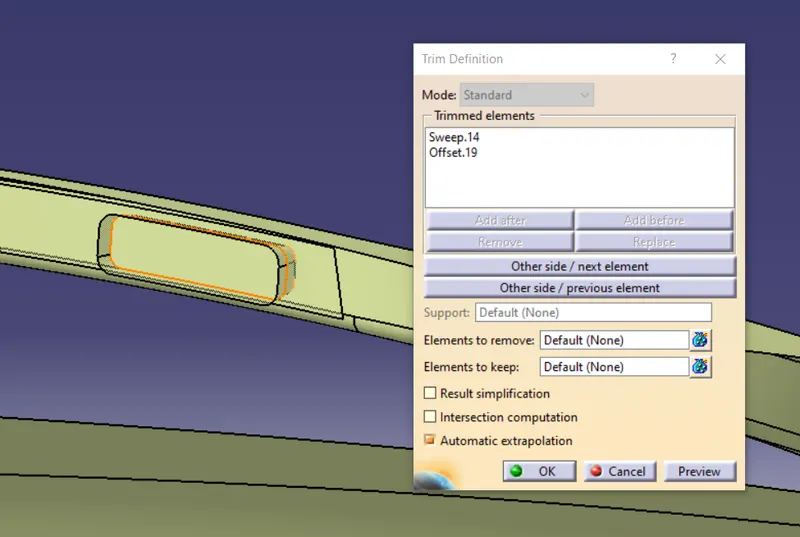
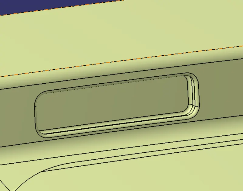
Then I will just provide the holes for fitting the hinge. The hinge mounting is shown below:
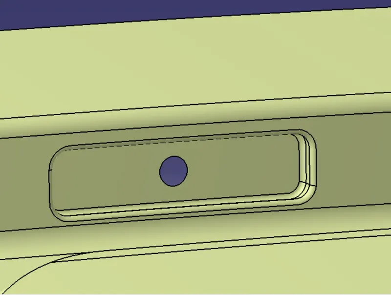
Hinge Reinforcement - Hinge Reinforcements are added in this region to compensate for the weak areas that are developed due to the continuous opening and closing of the backdoor. For creating the reinforcements I will extract the mounting surface and surfaces surrounding the mounting region, offset them to 0.75mm, and split the extra portion.
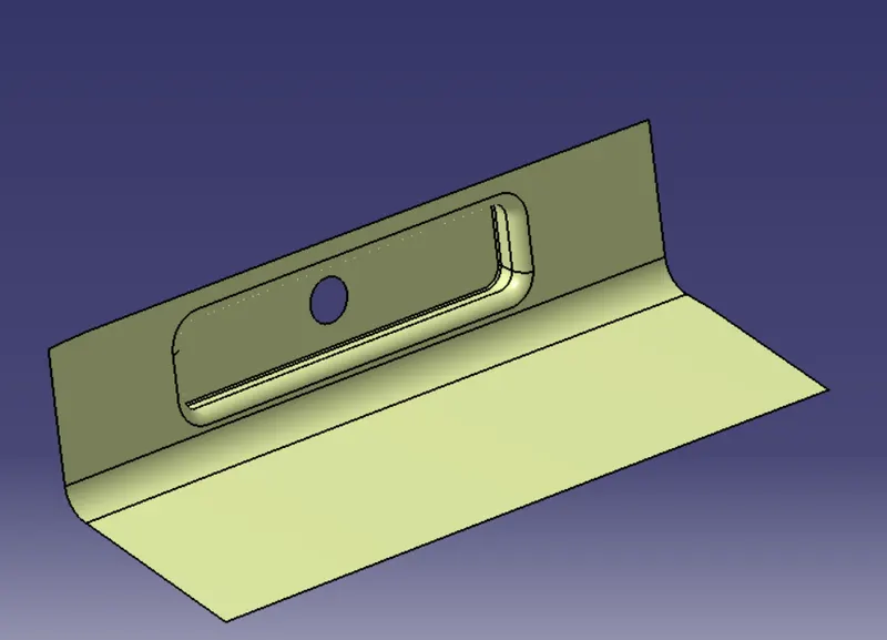
Then I will just thicken the above-shown surface to 1mm and that will be my reinforcement. The hinge reinforcement is shown below:
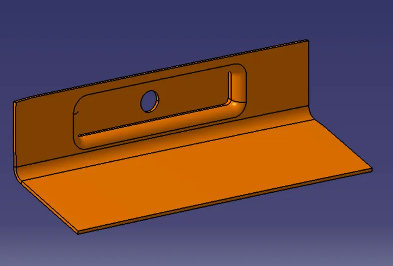
Latch Mounting - latch and striker forms the locking mechanism of the backdoor with the car. Before creating the latch mounting I will just mirror the half surface of the inner panel to get the complete inner panel.
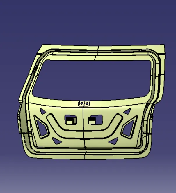
Now to find out out the position of the latch I will first have to find the center point of the hinges. so the center point of the hinges is shown below:
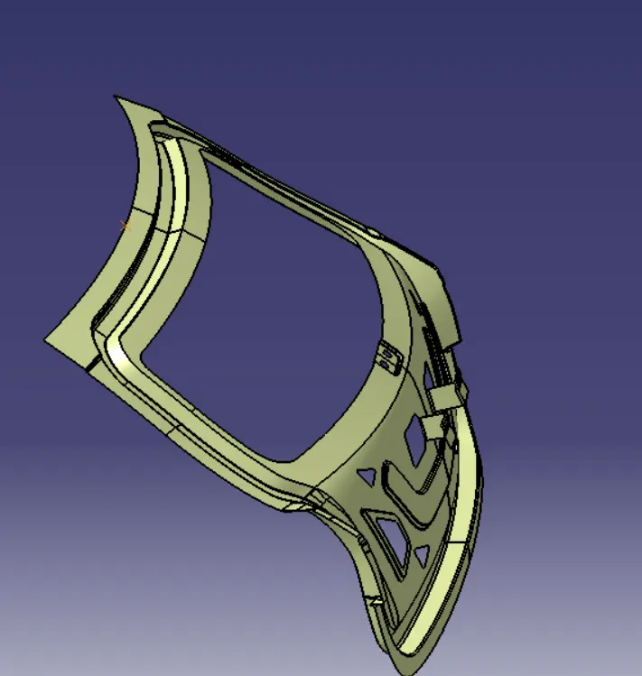
Then from that center point, I will draw a circle that will the trajectory of the latch and striker. The circle is shown below:
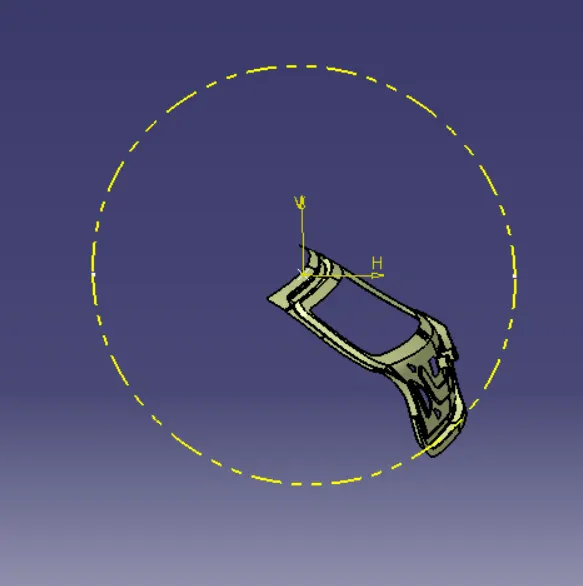
The latch will be positioned at the center of the backdoor so I will create one tangent line to the circle near the center of the backdoor and I will create one intersection point of the tangent line and the circle and using that point I will create the sketch for the latch mounting.
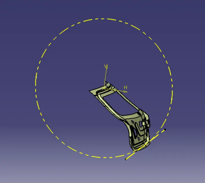
Now I will create the sketch and sweep that sketch giving a draft of over 7 degrees along that tangent line.
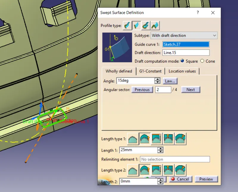
Then I will trim the sweep with the offset to get the mounting and provide the fillets
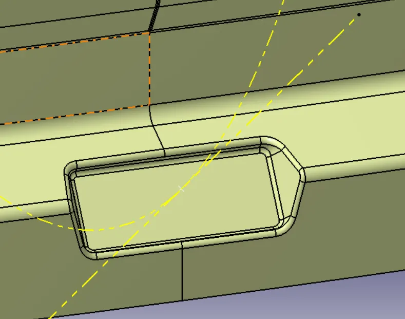
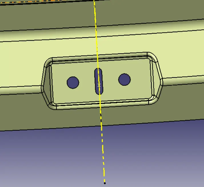
Then I will just provide the holes and space for the hook to fit in for that I will just create the sketch, project it on the surface, and split them.
Latch Reinforcement - Due to continuous opening and closing of the backdoor and also slamming of the door the area becomes weaker due to stresses induced so for providing extra strength reinforcements are added to it. For creating the reinforcement I will just extract the base surface of the mounting
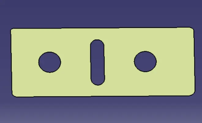
Then I will just thicken it to 1mm to get the reinforcement. The latch reinforcement is shown below:
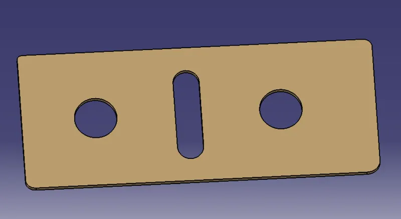
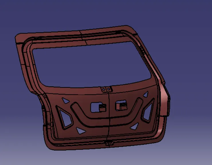
Now all the mounting and reinforcements are completed and now I will just make the solid body of the inner panel by thickening it to 0.75 mm upwards. The solid body of inner panel is shown below:
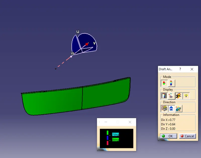
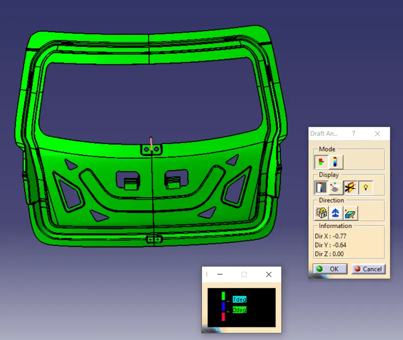
Draft Analysis - Draft analysis is a technique to analyze whether the component created is manufacturable or not based on the draft conditions applied. So here I will provide the direction in which the component should be ejected to get the easy removal. My direction will be the tooling axis that I have created.
The minimum draft value for the Automotive plastic component is 3 degrees and for those sheet metal components, 7 degrees of the draft is suitable. The draft is provided to the component for easy removal from the mold in the case of the plastic components.
The draft Analysis of the upper outer panel is shown below:
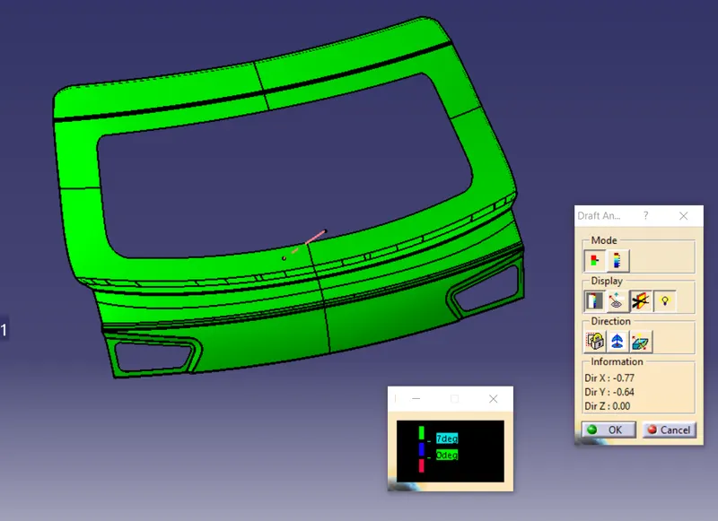
The draft analysis of the lower outer panel is shown below:
The draft analysis of the inner panel is shown below:
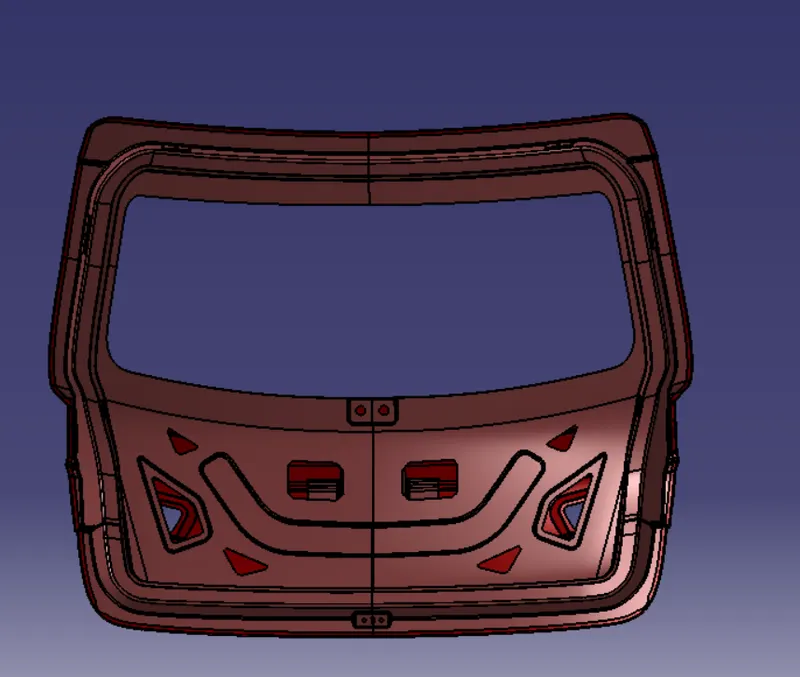
RESULT - The design of the backdoor is completed and the final cad model is shown below:
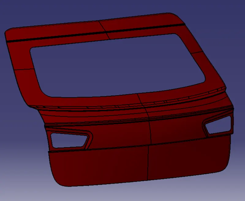
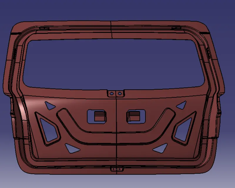
The combined outer and inner panel is shown below:
The hemming of the outer and inner panel is shown below:
CONCLUSION - This concludes the design of the Backdoor of the car using the appropriate design methodologies, providing the necessary Reinforcements and embosses.