Week 4-1D Element Creation Challenge
AIM - To create 1 D elements on the given model of the parallel bracket following the parameters given and to mesh the component.
OBJECTIVE - 1) To mesh the component with a size of 5 units.
2) Create 1 D elements following the parameters mentioned below:
a. Rod element:- Translational DOF should be Constrained with RBE2 link
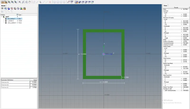
Cross-Section: BOX- Dimension a= 12 mm
dimension b=10 mm
Thickness t= 0.75 mm
b. Beam element:- All DOF should be constrained with RBE3 link
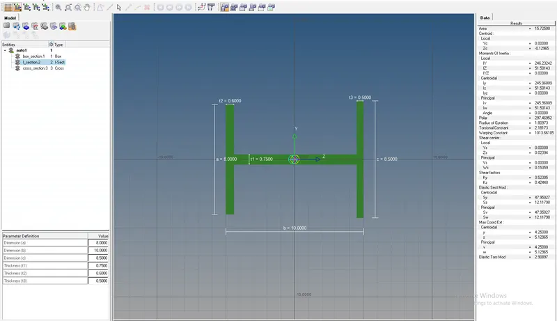
Cross-Section: I Section- Dimension a= 8 mm
Dimension b= 10 mm
Dimension c= 8.5 mm
Thickness t1= 0.75 mm
Thickness t2= .6 mm
Thickness t3= .6 mm
c. Bar element:- Constrain only x and y DOFs With RBE3 link
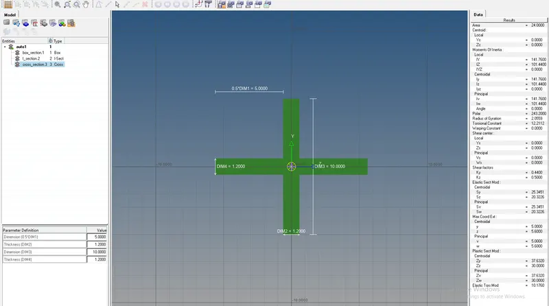
Cross-section: X section- Dimension DIM1= 5 mm
Thickness DIM2= 1.2 mm
Dimension DIM3= 10 mm
Thickness DIM4= 1.2mm
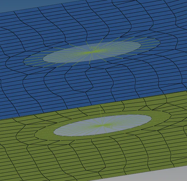
d. & e. Apply the mass of magnitude 10 with the RBE2 link
f. Join the two components with Spring elements
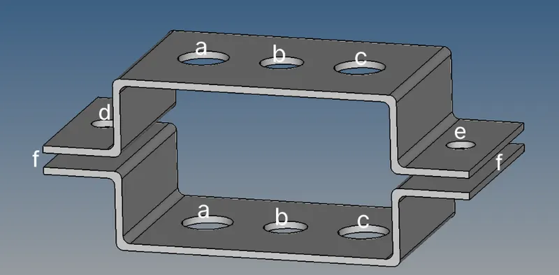
PROCEDURE - To start the procedure, I will first import the model. so for that I will go to import geometry and import the file to the software. After importing the model is shown below:
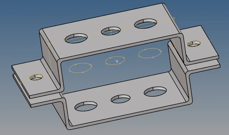
After importing the model I have to find the mid surface of both plates.
Midsurface modeling is a technique for creating a simplified shell representation of a solid model. Midsurface modeling can reduce the computational expense of analyzing a complete solid model when a shell model with a defined thickness and fewer details is suitable for the required analysis. Midsurface modeling is best suited to thin solids or thin-walled solids where wall thickness is constant or where reasonable approximations of the wall thickness at each point can be made easily.
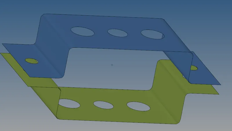
To find the mid surface of the plates will go to mid surface command under geometry and extract the mid surface of both the plates. Before creating the mid surface I have to make sure that both the plates are separate components. The mid surface of both the plates are shown below;
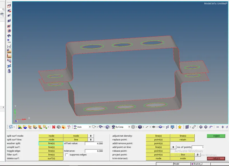
Now before meshing this I have to create the washer split for the holes. The washer split will be 4 mm offset from the holes
Then I will mesh the component defining the element size as 5 units. meshing option is available under the 2D section. The mesh of the component is shown below:
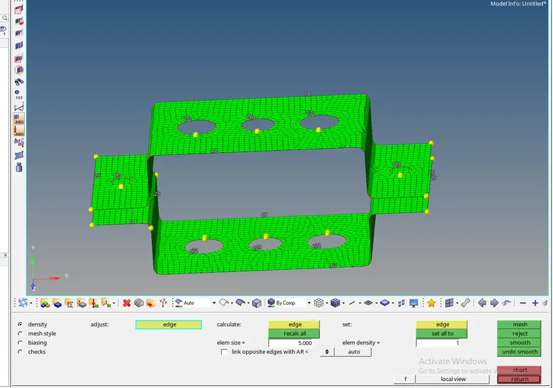
Here we can see that the mesh around the hole is not good so I have tried to improve the mesh by increasing the nodes on the areas which I feel are not properly meshed. The final mesh of the component is shown below:
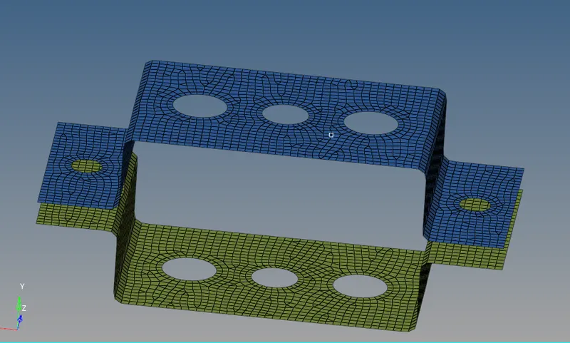
After meshing the component I will create the 1D elements. so I will create the Rbe2 and Rbe3 elements around the holes of the plates.
First creating the Rbe2 elements which have all translational degrees of freedom constrained. so for that, I will select the rigids under the 1D section.
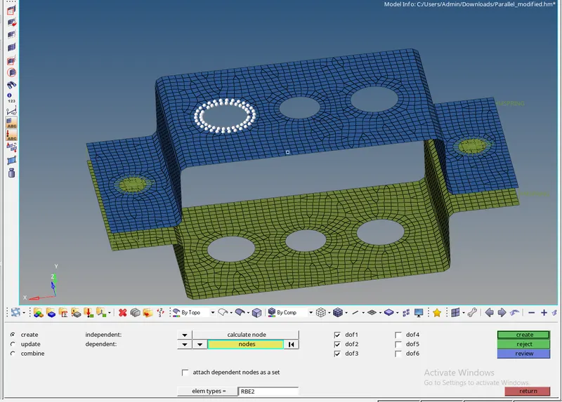
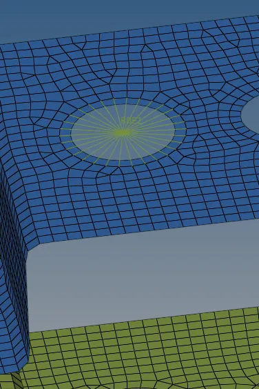
similarly for the bottom plate
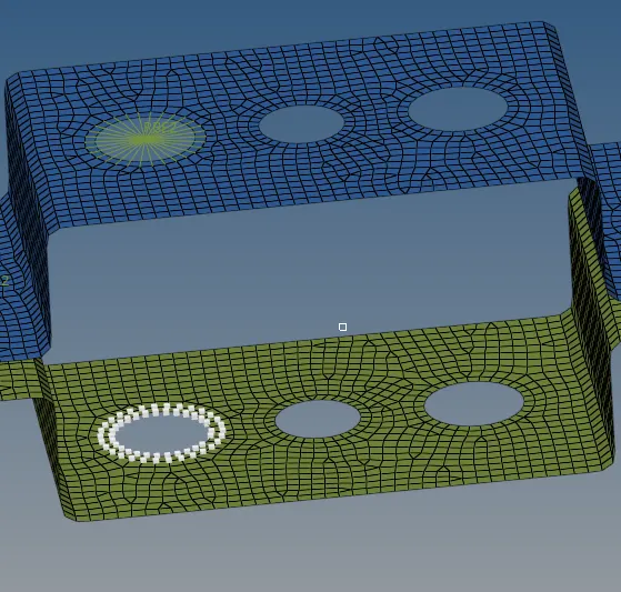
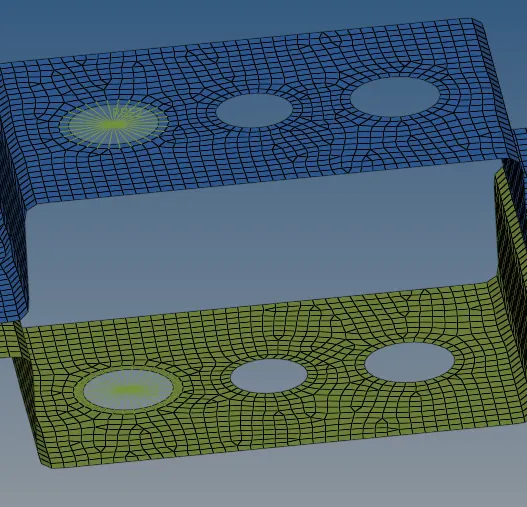
Then I have to create the 1D rod element so again under the 1D section, I will go to rods and select the nodes and will create the element.
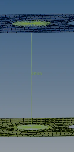
Then I will create the Rbe3 elements with all the degrees of freedom constrained
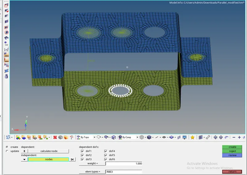
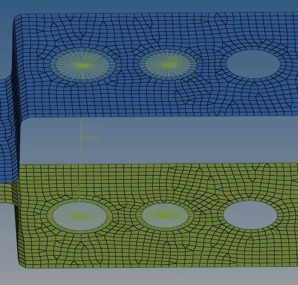
then I will create the beam element by selecting the bars under the 1D section and then selecting the element type as Cbeam
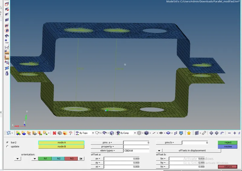
then for the hole C also I will create the Rbe3 elements with constraints in only the x and y direction
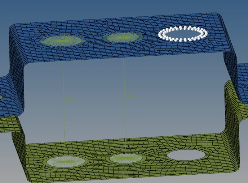
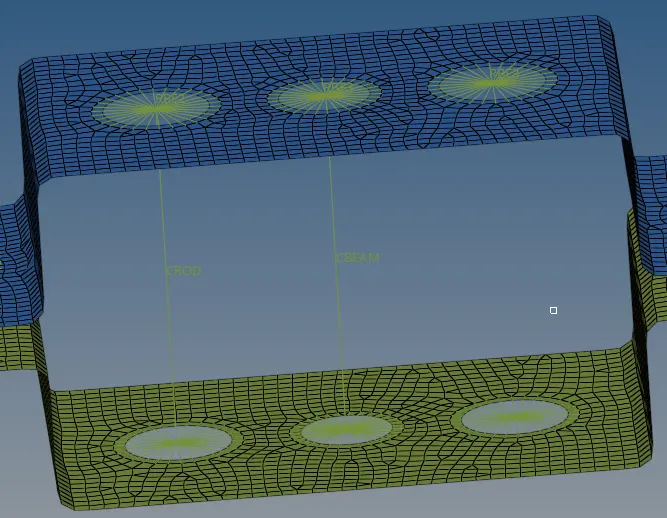
then for this, I have to create the bar element so I will select the bar under the 1D section and create it.

Then I will define a cross-section for all these elements that I created. For defining the cross-section I will go to the hyperbeam and then the standard section and finally define the section.
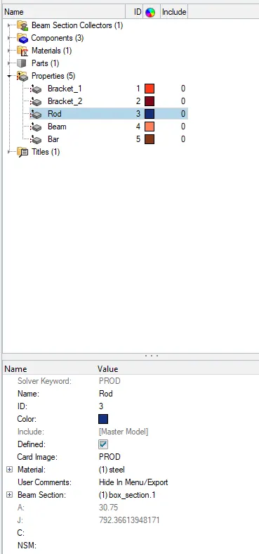
For the rod element the cross-section will be a box section as shown below:
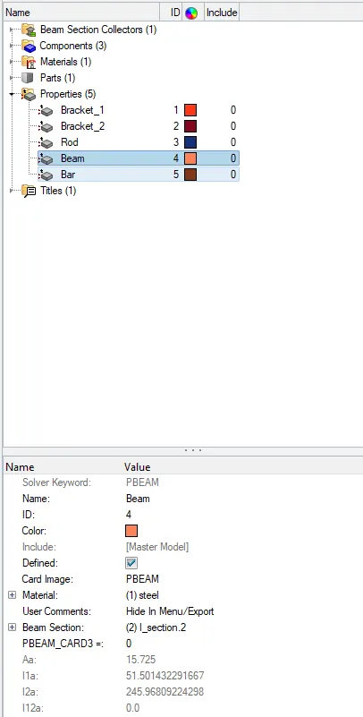
For the beam element the cross-section will be standard I section shown below:
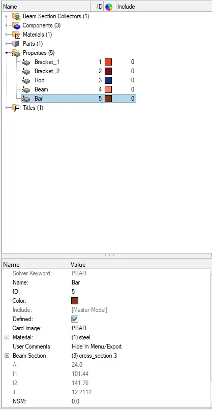
For the bar element the cross-section will be cross(X) section shown below:
Now I have created Rbe2 elements for the side holes also following the same procedure as I did for the other holes. The elements are shown below and I have also applied the masses to the nodes as well by selecting the masses option under the 1D section.
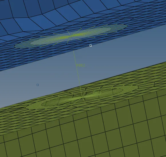
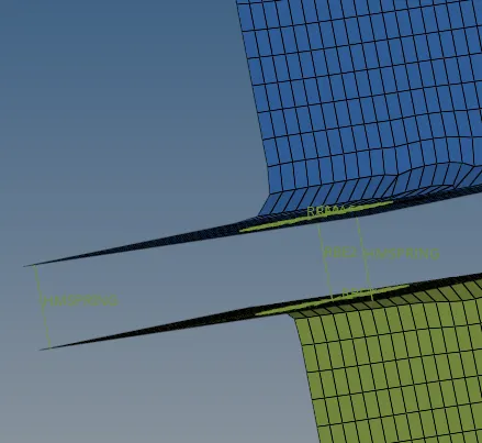
Then at last I will join two components with sprong elements. So for joining the plates under the 1D section I will select the springs and then change the element type to HMspring then select the nodes and join them. So here both the plates will be joined at the four corners.
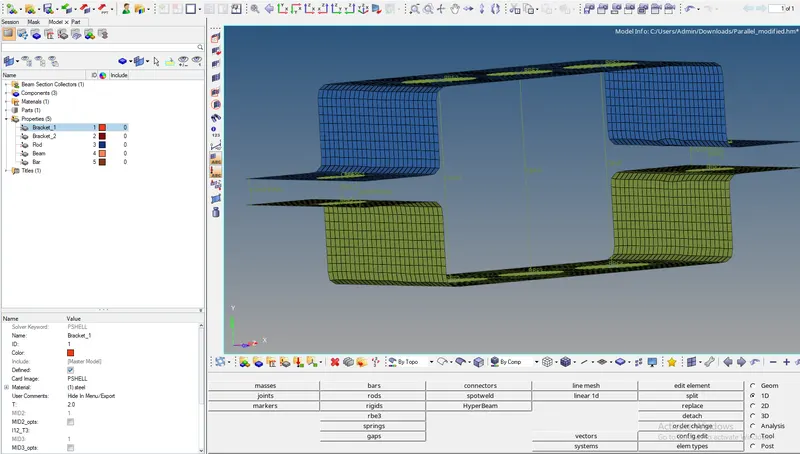
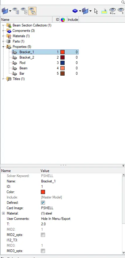
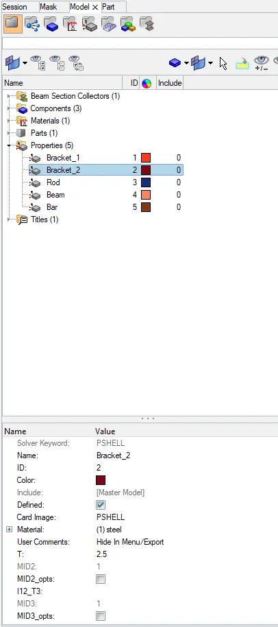
here I have also created the properties for both the brackets and for beam, bar, and rod and after updating them properties are shown below:
RESULT - The final model of the parallel bracket is shown below:
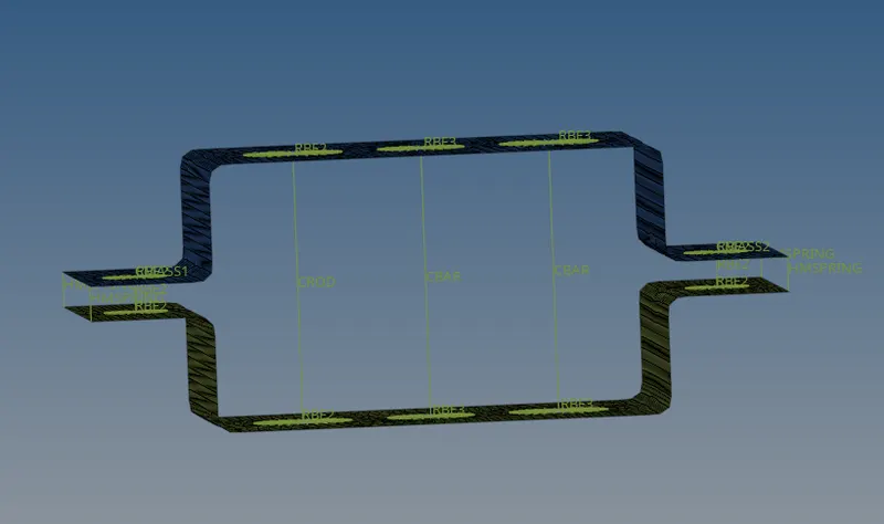
The 1 D detailed element representation is shown below:
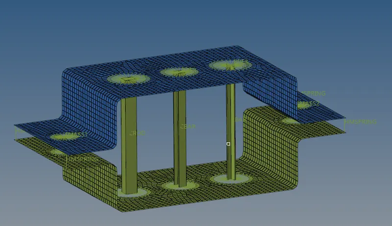
The 2D detailed element representation is shown below:
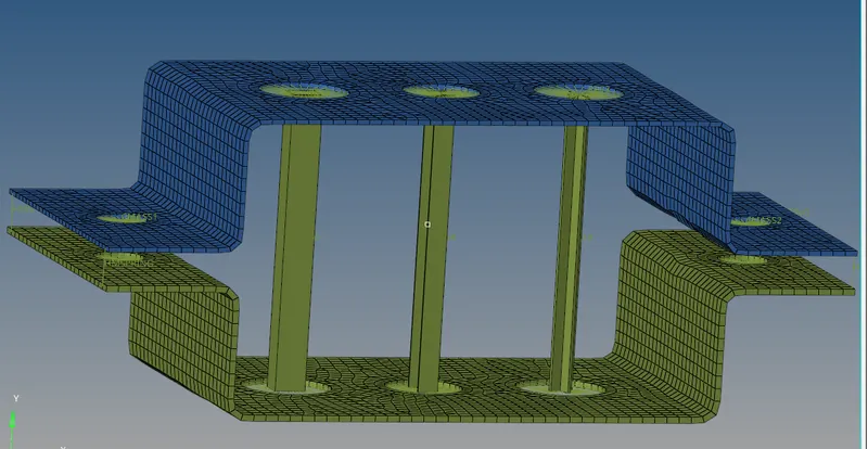
here the thickness I have applied is different for both the bracket. The upper bracket has a thickness of 2 mm and the lower bracket has a thickness of 2.5mm.
CONCLUSION - The creation of 1D elements on the parallel bracket model along with the meshing of the component has been completed successfully and the results are shown.