Final Project: Electric Rickshaw modelling
AIM - To create a detailed MATLAB model of an electric rickshaw (three-wheel passenger vehicle).
INTRODUCTION - Electric Rickshaws or E-Rickshaws are one of the preferred models of transportation for passengers. They are gaining popularity as they are an alternative to petrol, diesel, or CNG-driven vehicles. Hence are eco-friendly and do not add to the carbon dioxide level in the air. The cost of commuting is comparably less and comfortable. And customers can avail of this product at a pocket-friendly price
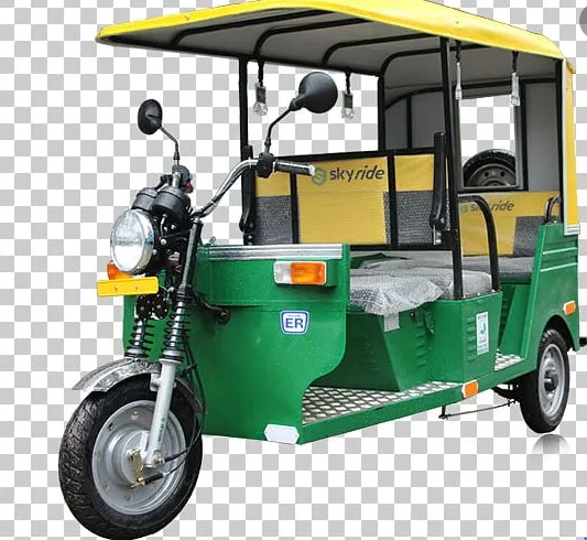
These rickshaws have an M.S(Mild Steel) tubular chassis, consisting of three wheels with a differential mechanism at the rear wheels. The motor is a brushless DC motor manufactured mostly in India and China. The electrical system used in the Indian version is 48V and Bangladesh is 60V. The body design from the most popular Chinese version is of very thin iron or aluminum sheets. Vehicles made in fiber are also popular because of their strength and durability, resulting in low maintenance, especially in India. The body design is varied from load carriers, passenger vehicles with no roof, to full body with windshields for drivers' comfort. It consists of a controller unit. They are sold on the basis of voltage supplied and current output, also the number of MOSFET (metal oxide field-effect transistors) used. The battery used is mostly a lead-acid battery with a life of 6–12 months. Deep cycle batteries designed for electric vehicles are rarely used. The weight of the electric car has also been a recurring design difficulty in them.
The layout of the electric rickshaw is similar to that of an electric car or electric vehicle.
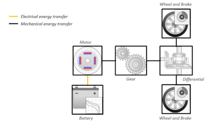
The main electronic components which make the powertrain are the motor, controller, harness, batteries, and throttle. Any mismatch among any of these components is undesirable and may compromise vehicle performance.
The chassis is the main part that ensures the drive quality and safety of the vehicle. It is made of mild steel. These days, most of the locally-made chassis are often built without proper design, leading to an imbalance in the drive, and often causing the vehicle to pivot or topple very easily. The chassis manufactured by a professional E Rickshaw Manufacturer is robust as the design adheres to all quality / technical parameters, which are often ignored by others. The chassis, if inaccurately made, will have handling problems, will be damaged easily, and corrode if not treated for resisting certain chemicals (from the battery or otherwise) or moisture.
The motor power used in most e rickshaws is 650W to 1250W, the latest government norms allow it to be 650W, most of them run on 850W and higher, which adversely affects the battery life. The controller used is ~ 40A, 48V output, uses 14, 18, or 24 MOSFETs, and powers all-electric components.
A good quality controller must be used to increase the performance of the motor and other overheating issues. A controller should be installed with an electrical brake cut-off, and which usually are removed by common rickshaw mechanics in order to achieve a continuous torque or improper functioning of the brakes.
The braking system is mechanical drum brakes. Service and maintenance are required for proper vehicle functioning as improper brake adjustments may heat up the motor and controllers and damage brake shoes. It may also reduce the mileage of the vehicle.
PROCEDURE -
First, let's see what Simulink is?
Simulink - Simulink is a MATLAB-based graphical programming environment for modeling, simulating, and analyzing multidomain dynamical systems. Its primary interface is a graphical block diagramming tool and a customizable set of block libraries. It offers tight integration with the rest of the MATLAB environment and can either drive MATLAB or be scripted from it. Simulink is widely used in automatic control and digital signal processing for multidomain simulation and model-based design.
The steps by which I created the model using different blocks are shown below: so at first, I started with the tire block.
1) Tire block - The Tire (Magic Formula) block models the tire as a rigid wheel-tire combination in contact with the road and subject to slip. When torque is applied to the wheel axle, the tire pushes on the ground (while subject to contact friction) and transfers the resulting reaction as a force back on the wheel. This action pushes the wheel forward or backward. If you include the optional tire compliance, the tire also flexibly deforms under load. The tire block is shown below:
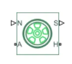
As you can see the block has 4 ports (N, S, A, H) in which A is the input port and s is the output port
N- Physical signal input port associated with the normal force acting on the tire. The normal force is positive if it acts downward on the tire, pressing it against the pavement.
A - Mechanical rotational port associated with the axle that the tire sits on.
H - Mechanical translational port associated with the wheel hub that transmits the thrust generated by the tire to the remainder of the vehicle.
S - Physical signal output port associated with the relative slip between the tire and road.
There are four tire blocks I have used here 2 for the front axle and two for the rear axle
The parameters of the tire that I used in my model are shown below:
For front axle tires :
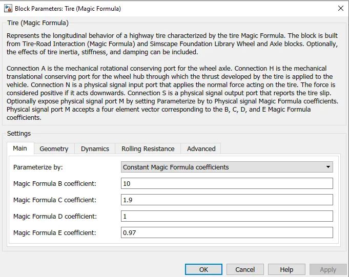
and for Rear axle tires :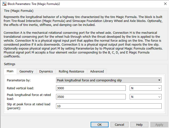
All these values are my assumed parameters, The rolling radius of all 4 wheels was 0.3 and here i have kept the rolling resistance coefficient of all four wheels 0.015
The next block I have used was the vehicle body block:
2) vehicle body - The Vehicle Body block represents a two-axle vehicle body in longitudinal motion. The vehicle can have the same or a different number of wheels on each axle. For example, two wheels on the front axle and one wheel on the rear axle. The vehicle wheels are assumed identical in size. The vehicle can also have a center of gravity (CG) that is at or below the plane of travel.
The block accounts for body mass, aerodynamic drag, road incline, and weight distribution between axles due to acceleration and road profile. Optionally include pitch and suspension dynamics. The vehicle does not move vertically relative to the ground. The block has an option to include an externally defined mass and an externally defined inertia. The mass, inertia, and center of gravity of the vehicle body can vary over the course of simulation in response to system changes. The vehicle block is shown below:
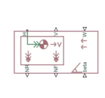
The block has 6 ports (NR,NF,H,V,W,beta)
NR - Physical signal output port for normal force on the rear axle. Wheel forces are considered positive if acting downwards.
NF - Physical signal output port for normal force on the front axle. Wheel forces are considered positive if acting downwards.
H - This port is used to connect the hub of the wheel
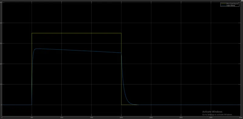
V - Physical signal output port for vehicle longitudinal velocity. This is my output velocity which I will observe in the plot.
W - Physical signal input port for headwind speed. Here I have given the wind speed as 2 m/s
beta - Physical signal input port for road incline angle. The inclination angle in my case is 0
The parameters of the vehicle body block are shown below:
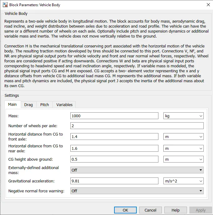
As you can see above the mass I have taken is 1000kg, and the drag parameters I have taken are as follows:
The drag force will resist the motion of the vehicle means it will act opposite to the direction of motion of the vehicle.
Frontal area = 0.6 `m^2`, Air density = 1.25 `frac(kg)(m^3)`, Drag coefficient = 0.2 and pitch variables and other variables are off.
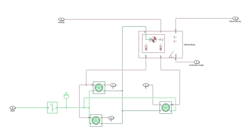
Then I have made the connection of two blocks that are the vehicle body block and tire block the connections are shown below:

Here you can see that the hubs of front tires are connected to the hubs of rear tires and all the hubs are connected to the H port of the vehicle body block and the ports of front and rear tires are connected to their adjacent front and rear tires to form the front and rear axle.
similarly, the N port of front tires and rear tires are connected to the N ports of adjacent front and rear tires which are further connected to the NF and NR ports of the vehicle body block.
The sport of tire represents the slip that I have displayed in the output for each individual tire.
3)Gear block - Here I have used a simple gear block. The Simple Gear block represents a gearbox that constrains the connected driveline axes of the base gear, B, and the follower gear, F, to corotate with a fixed ratio that you specify. You choose whether the follower axis rotates in the same or opposite direction as the base axis. If they rotate in the same direction, the angular velocity of the follower, ωF, and the angular velocity of the base, ωB, have the same sign. If they rotate in opposite directions, ωF and ωB have opposite signs. The gear block is shown below:
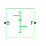
gear ratio (G) is defined as `frac{Nb)(Nf)` where Nb is the number of teeth in base gear and Nf is the number of teeth in follower gear.
This block has two ports B and F
B - Rotational mechanical conserving port associated with the base, or input, shaft.
F - Rotational mechanical conserving port associated with the follower, or output, shaft.
so I have connected the F port to the rear axle of the vehicle and B will be input to the gear which will come from the motor.
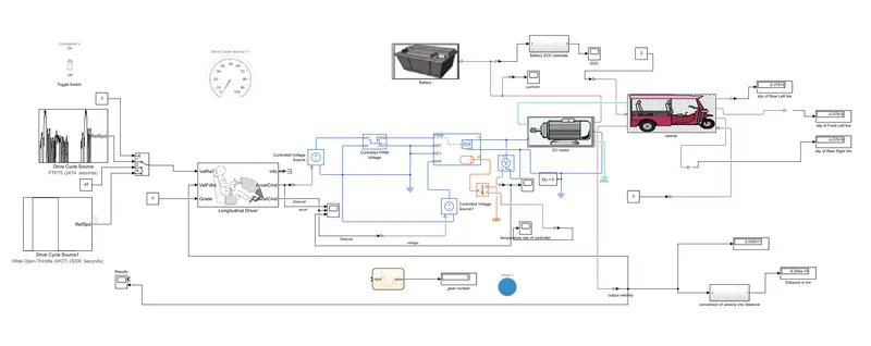
so I have made the subsystem combining the three blocks that is the tires, vehicle body, and gear block, and named it 'vehicle'.
the whole subsystem looks like this:
4) DC motor - A DC motor is a motor that requires DC signal input for its working but here I have used a permanent magnet DC motor.
The working principle of a DC motor is when a current-carrying conductor is placed in a magnetic field, it experiences a force. A permanent magnet DC motor also works on the same principle. In a PMDC motor, permanent magnets (located in stator) provide a magnetic field, instead of the stator winding. The stator is usually made from steel in cylindrical form. Permanent magnets are usually made from rare earth materials or neodymium.
The rotor is a slotted armature that carries armature winding. The rotor is made from layers of laminated silicon steel to reduce eddy current losses. Ends of armature winding are connected to commutator segments on which the brushes rest. The commutator is made from copper and brushes are usually made from carbon or graphite. DC supply is applied across these brushes. The commutator is in the segmented form to achieve unidirectional torque. The reversal of direction can be easily achieved by reversing the polarity of the applied voltage.
The DC motor block is shown below:
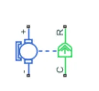
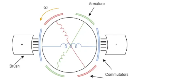
There are 4 ports in the motor block above
+ve terminal - Electrical conserving port associated with the DC motor positive terminal.
-ve terminal - Electrical conserving port associated with the DC motor negative terminal.
c - Mechanical rotational conserving port associated with the DC motor case.
R - Mechanical rotational conserving port associated with the DC motor rotor.
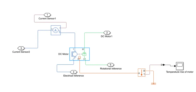
here we can see that the thermal port of the DC motor is also shown because I want to show the temperature rise of the motor. so the H port in the above fig represents the thermal port.
The block has an optional thermal port, hidden by default. To expose the thermal port, right-click the block in your model, and then from the context menu select Simscape > Block choices > Show thermal port. This action displays the thermal port H on the block icon and exposes the Temperature Dependence and Thermal Port parameters.
The thermal port is connected to the temperature sensor and the sensor is further connected to the scope for observing the rise.
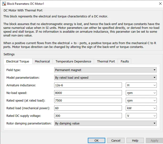
The motor parameters are shown below:
5) current sensor block - The Current Sensor block represents an ideal current sensor, that is, a device that converts current measured in any electrical branch into a physical signal proportional to the current. Connections + and – are electrical conserving ports through which the sensor is inserted into the circuit. The connection I is a physical signal port that outputs the measurement result. The current sensor block is shown below:
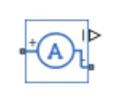
It has two ports +ve and -ve the -ve will be connected to the motor and the +ve will be connected to the H bridge block.
6) H-bridge block - An H-bridge is a simple circuit that lets you control a DC motor to go backward or forward. You normally use it with a microcontroller, such as an Arduino, to control motors. An H-bridge is an electronic circuit that switches the polarity of a voltage applied to a load.
The term H-bridge is derived from the typical graphical representation of such a circuit. Suppose An H-bridge is built with four switches (solid-state or mechanical). When the switches S1 and S4 are closed (and S2 and S3 are open) a positive voltage is applied across the motor. By opening S1 and S4 switches and closing S2 and S3 switches, this voltage is reversed, allowing reverse operation of the motor.
Using the nomenclature above, the switches S1 and S2 should never be closed at the same time, as this would cause a short circuit on the input voltage source. The same applies to switches S3 and S4. This condition is known as shoot-through.
The H bridge block is shown below:
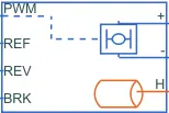
as you can see it has six ports:
+ve terminal - Electrical conserving port associated with the positive load connection.
-ve terminal - Electrical conserving port associated with the negative load connection.
PWM - Electrical conserving port associated with the pulse-width modulated signal. The voltage is defined relative to the REF port.
REF - Electrical conserving port associated with the floating zero volt reference.
REV - Electrical conserving port associated with the voltage that controls when to reverse the polarity of the H-Bridge block output.
BRK - Electrical conserving port associated with the voltage that controls when to short circuit the H-Bridge block output.
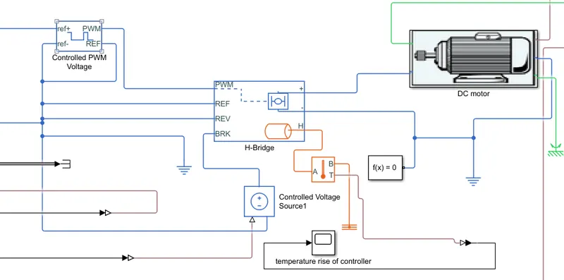
The +ve terminal port I have connected to the positive terminal of the current sensor block is already explained above.
The -ve terminal is connected to electrical reference, the H bridge PWM port will get its input from the controlled PWM voltage block which I will describe in the next section.
Here I am not running my vehicle in the reverse direction so I will connect that port to the ground, the reference port is also connected to controlled PWM voltage which will be further connected to the ground. The BRK port will be connected to a controlled voltage source which will be again connected to a ground-controlled voltage source that will provide the controlled input as per driver requirement.
here also I have to show the temperature rise of the controller. so again I have used the thermal port H and again it is connected to a temperature sensor which is further connected to the scope block to observe the temperature rise.
The parameter that I have used for the H bridge is shown below:
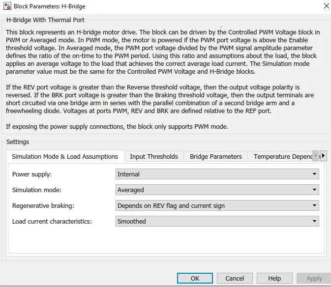
here you can see that the power supply I have given is internal and the simulation model is averaged, the regenerative braking is also enabled.
The input thresholds I have kept as default only and in bridge parameter, the output voltage amplitude I have given is 320V, and freewheeling diode resistance I have kept as default only that is 0.05 ohm.
the input threshold is shown below:
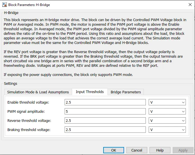
Here in the simulation mode there are two modes PWM and averaged:
PWM - the H-Bridge block output is a controlled voltage that depends on the input signal at the PWM port. If the input signal has a value greater than the Enable threshold voltage parameter value, the H-Bridge block output is on and has a value equal to the value of the Output voltage amplitude parameter.
Averaged - This mode has two Load current characteristics options:
-
smoothed - The smoothed option assumes that the current is practically continuous due to load inductance.
-
unsmoothed - The unsmoothed option assumes that the current is discontinuous.
I have set it to average because I want to simulate the results faster.
Braking mode is invoked when the voltage presented at the BRK port is larger than the Braking threshold voltage.
7) Controlled PWM voltage block - This block will give input to the H bridge block. The Controlled PWM Voltage block represents a pulse-width modulated (PWM) voltage source.
-
Electrical input ports — The block calculates the duty cycle based on the reference voltage across its ref+ and ref- ports. This modeling variant is the default.
-
PS input — Specify the duty cycle value directly by using an input physical signal port.
This block will provide pulses and from these pulses, the variable output voltage will be produced and motor speed and torque are going to change.
The block looks like this:
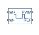
Here you can see that 4 ports are there:
ref+ = positive electrical reference port which will be connected to a controlled voltage source.
ref - = Negative electrical reference.
PWM - Electrical conserving port associated with the pulse-width modulated signal.
REF - This is an Electrical conserving port associated with the floating zero volt reference.
the connection of these ports is: the PWM port is connected to the PWM port of the H bridge so this will act as an input to the motor, the REF port is connected to the Reference part of the H bridge. The ref- will be connected to the ground, Now the input to the control system is given by a controlled voltage source so the ref+ will be connected to the controlled voltage source.
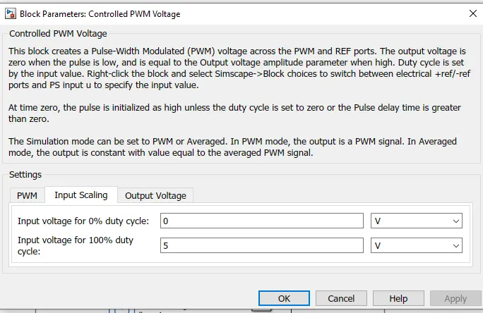
Duty cycle - Duty cycle is a parameter that is measured in percentage which shows the amount of time the switch is on.
Duty cycle = `frac{(Time)on}{Total time}`
Total time = (Time)on + (Time)off
Duty cycle basically controls the output voltage.
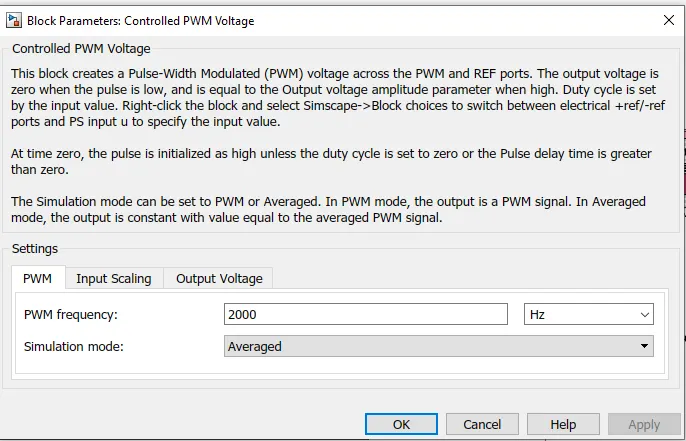
Here the input voltage for the 100 % duty cycle I have kept is 5V and the output voltage amplitude is also 5V
The parameters of the PWM block are shown below:
8) Controlled voltage source - The Controlled Voltage Source block represents an ideal voltage source that is powerful enough to maintain the specified voltage at its output regardless of the current flowing through the source.
The output voltage is V = Vs, where Vs is the numerical value presented at the physical signal port.
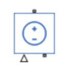
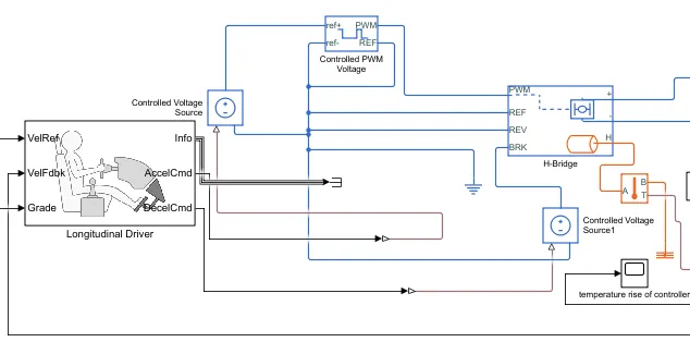
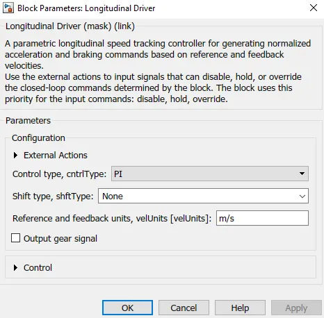
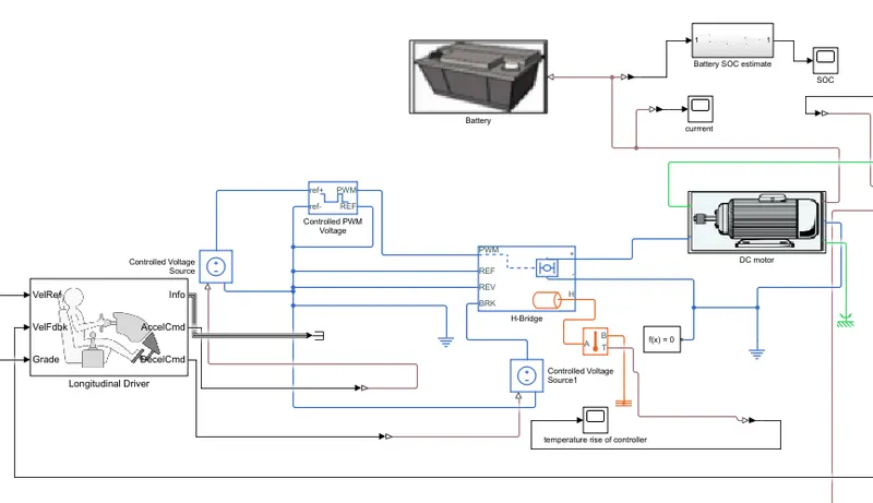
here u can see two controlled voltage sources the +ve of 'controlled voltage source' is connected to the ref+ of the controlled PWM block and the 'controlled voltage source' is getting its input from the Acceleration command of the longitudinal block. In another one that is the 'controlled voltage source 1', the +ve is connected to the BRK port of the H bridge and the physical signal input is connected to the deceleration command of the longitudinal driver block.
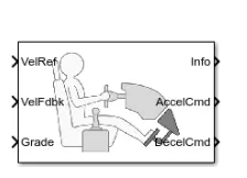
Decelcmd - This port is for the deceleration command or braking command and again just like the acceleration command, it is normalized from 0 to 1.
The connections are shown below:
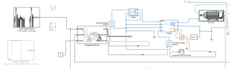
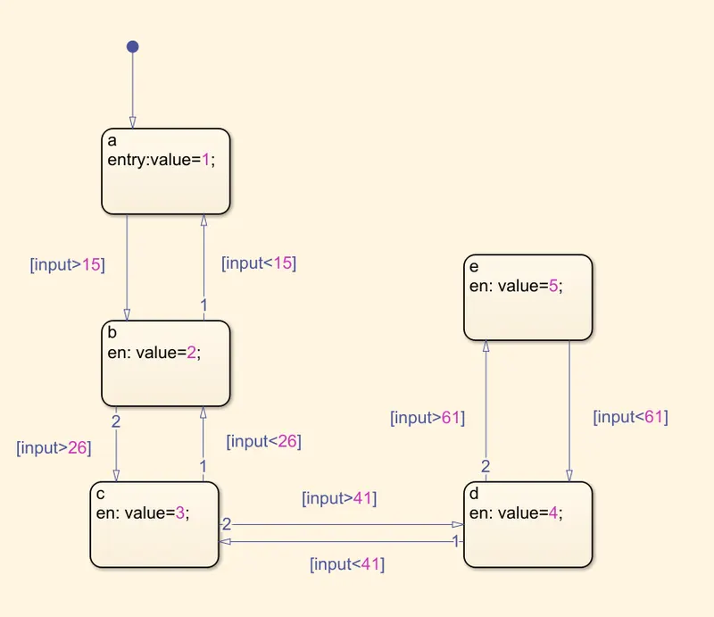
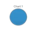
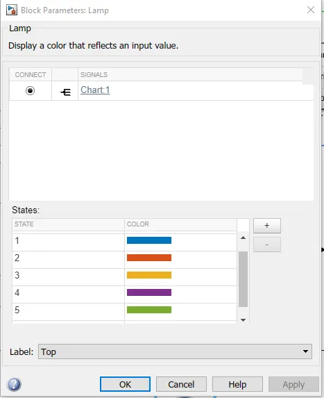
| GEAR NUMBER | COLOUR |
| 1 | BLUE |
| 2 | ORANGE |
| 3 | YELLOW |
| 4 | PURPLE |
| 5 | GREEN |