Week 8 - Simulation of a backward facing step in OpenFOAM
Aim: To stimulate an incompressible-laminar-viscous flow through the backward facing step geometry in OpenFoam.
Objectives: In this challenge, you are going to simulate an incompressible-laminar-viscous flow through the backward facing step geometry. You should perform a transient simulation. The solver can be chosen based on the physics of flow described. You need to explain the entire simulation procedure (how you set up the case). You should also provide explanations for every change you make inside the reference case files obtained from OpenFOAM tutorials. You can choose the inlet velocity such that the flow is laminar.
Solution:
Here, the flow is incompressible in nature, and divided the step geometry into five blocks and the nodes of each face are specified in order and those figures are shown below.
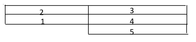
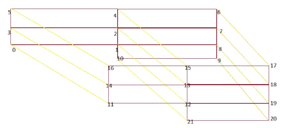
Now, to stimulate this case I selected the icoFoam solver and copied that into my openFoam run folder to get the results of the stimulation and velocity profiles and also the pressure profiles for different mesh Grading Factors.
Mesh specification
- Number of cells along the x direction (longer dimension) = 200
- Number of cells along the longer y direction = 20;
Case 1: To Simulate the flow without using any grading factor i.e., GF = 1
And for this I coded the vertices and boundaries of the figure in blockMeshDict file, as shown below
/*--------------------------------*- C++ -*----------------------------------*\ ========= | \\ / F ield | OpenFOAM: The Open Source CFD Toolbox \\ / O peration | Website: https://openfoam.org \\ / A nd | Version: 11 \\/ M anipulation |\*---------------------------------------------------------------------------*/FoamFile{ format ascii; class dictionary; object blockMeshDict;}// * * * * * * * * * * * * * * * * * * * * * * * * * * * * * * * * * * * * * //
convertToMeters 1;
vertices( (0 0 0) //0 (0.08 0 0) //1 (0.08 0.005 0) //2 (0 0.005 0) //3 (0.08 0.01 0) //4 (0 0.01 0) //5 (0.2 0.01 0) //6 (0.2 0.005 0) //7 (0.2 0 0) //8 (0.2 -0.01 0) //9 (0.08 -0.01 0) //10 (0 0 0.01) //11 (0.08 0 0.01) //12 (0.08 0.005 0.01) //13 (0 0.005 0.01) //14 (0.08 0.01 0.01) //15 (0 0.01 0.01) //16 (0.2 0.01 0.01) //17 (0.2 0.005 0.01) //18 (0.2 0 0.01) //19 (0.2 -0.01 0.01) //20 (0.08 -0.01 0.01) //21);
blocks( hex (0 1 2 3 11 12 13 14) (80 5 1) simpleGrading (1 1 1) hex (3 2 4 5 14 13 15 16) (80 5 1) simpleGrading (1 1 1) hex (2 7 6 4 13 18 17 15) (120 5 1) simpleGrading (1 1 1) hex (1 8 7 2 12 19 18 13) (120 5 1) simpleGrading (1 1 1) hex (10 9 8 1 21 20 19 12) (120 10 1) simpleGrading (1 1 1));
edges ( ); boundary( inlet { type patch; faces ( (11 14 3 0) (14 16 5 3) ); } outlet { type patch; faces ( (19 20 9 8) (18 19 8 7) (17 18 7 6) ); } upperwalls { type wall; faces ( (16 15 4 5) (15 17 6 4) ); } lowerwalls { type wall; faces ( (11 0 1 12) (21 10 9 20) (21 12 1 10) ); } frontAndBack { type empty; faces ( (0 3 2 1) (3 5 4 2) (2 4 6 7) (1 2 7 8) (10 1 8 9) (14 11 12 13) (16 14 13 15) (15 13 18 17) (12 21 20 19) (13 12 19 18) ); });
mergePatchPairs();
// ************************************************************************* //
Here, the vertices of each node are specified as (x,y,z) and then the boundaries are specified as inlet, outlet, upperwalls, lowerwalls, and frountAndBack. Then applied the command to merge the boundaries to patch.
Then specify the time step conditions in the contolDict file as shown below.
/*--------------------------------*- C++ -*----------------------------------*\ ========= | \\ / F ield | OpenFOAM: The Open Source CFD Toolbox \\ / O peration | Website: https://openfoam.org \\ / A nd | Version: 11 \\/ M anipulation |\*---------------------------------------------------------------------------*/FoamFile{ format ascii; class dictionary; location "system"; object controlDict;}// * * * * * * * * * * * * * * * * * * * * * * * * * * * * * * * * * * * * * //
application icoFoam;
startFrom startTime;
startTime 0;
stopAt endTime;
endTime 1;
deltaT 0.0005;
writeControl timeStep;
writeInterval 100;
purgeWrite 0;
writeFormat ascii;
writePrecision 6;
writeCompression off;
timeFormat general;
timePrecision 6;
runTimeModifiable true;
// ************************************************************************* //
Here, the stimulation time starts at o sec and ends at 1sec and stimulated to 100 iterations. And the dt value is specified as 0.0005
And defined the pressure conditions at each boundary fields as shown below.
/*--------------------------------*- C++ -*----------------------------------*\ ========= | \\ / F ield | OpenFOAM: The Open Source CFD Toolbox \\ / O peration | Website: https://openfoam.org \\ / A nd | Version: 11 \\/ M anipulation |\*---------------------------------------------------------------------------*/FoamFile{ format ascii; class volScalarField; object p;}// * * * * * * * * * * * * * * * * * * * * * * * * * * * * * * * * * * * * * //
dimensions [0 2 -2 0 0 0 0];
internalField uniform 0;
boundaryField{ inlet { type zeroGradient; } outlet { type fixedValue; value uniform 0; }
upperwalls { type zeroGradient; } lowerwalls { type zeroGradient; }
frontAndBack { type empty; }}
// ************************************************************************* //
And then defined the velocity conditions to each boundary field shown below.
/*--------------------------------*- C++ -*----------------------------------*\ ========= | \\ / F ield | OpenFOAM: The Open Source CFD Toolbox \\ / O peration | Website: https://openfoam.org \\ / A nd | Version: 11 \\/ M anipulation |\*---------------------------------------------------------------------------*/FoamFile{ format ascii; class volVectorField; object U;}// * * * * * * * * * * * * * * * * * * * * * * * * * * * * * * * * * * * * * //
dimensions [0 1 -1 0 0 0 0];
internalField uniform (1 0 0);
boundaryField{ inlet { type fixedValue; value uniform (1 0 0); } outlet { type zeroGradient; }
upperwalls { type noSlip; } lowerwalls { type noSlip; }
frontAndBack { type empty; }}
// ************************************************************************* //
Results:
Mesh stimulation:
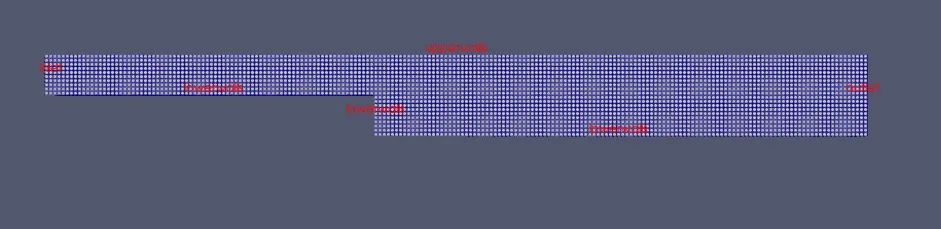
Pressure contour:
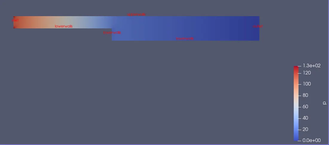
Uniform Velocity contour:
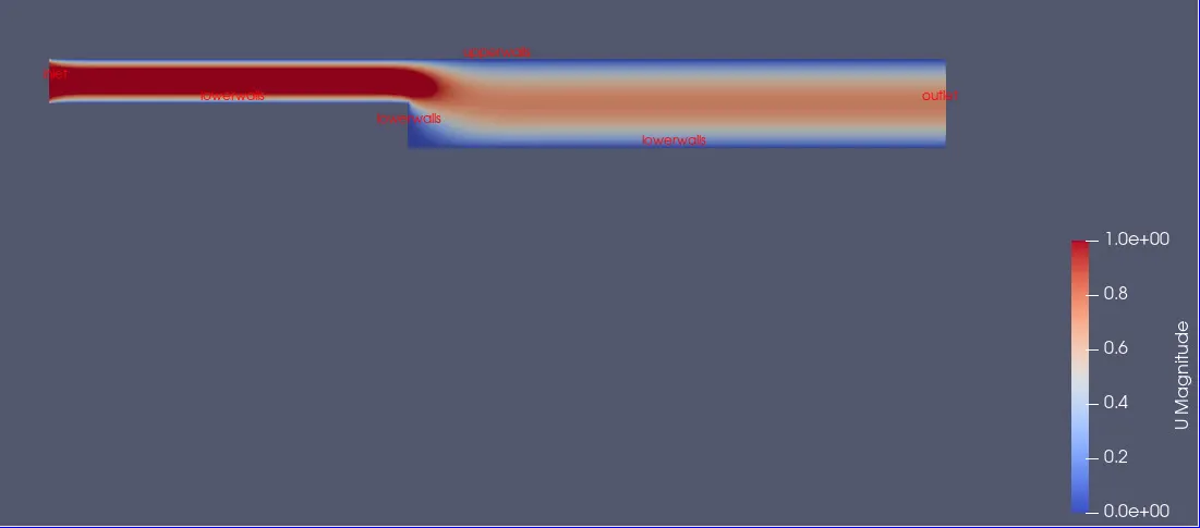
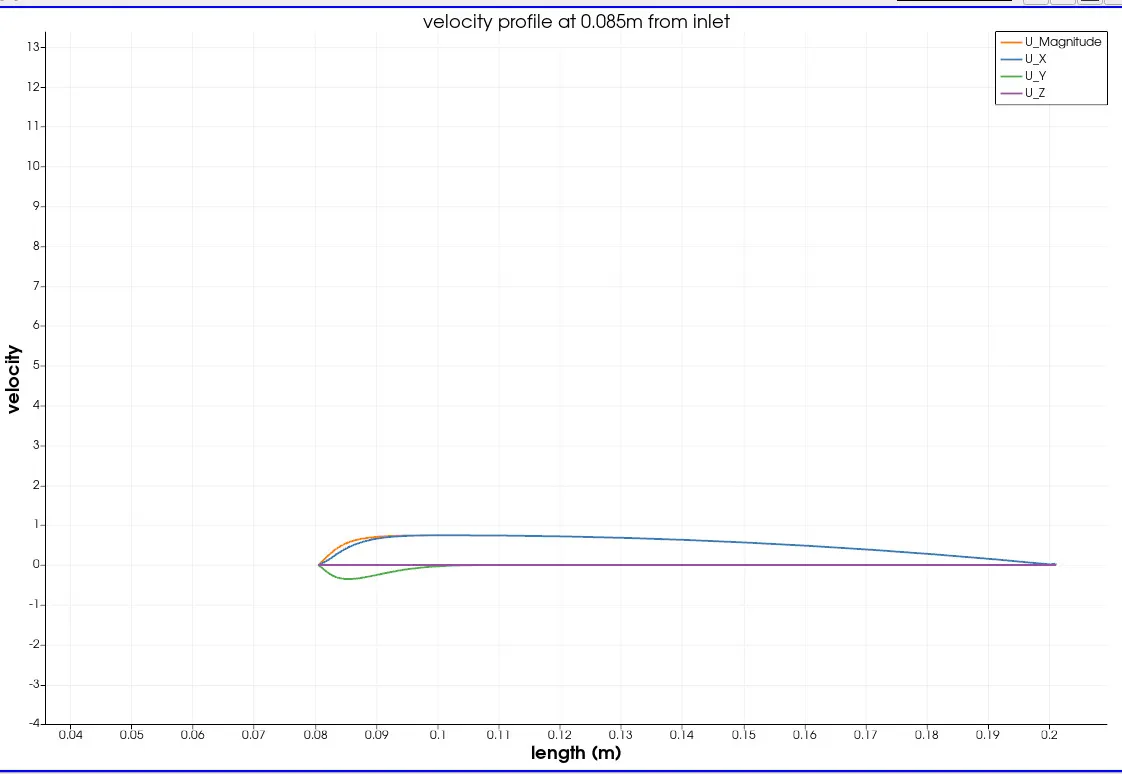
Here, at the end of the iterations the courant mean value is 0.342106 and max up to 0.744603
And, the initial velocity residuals along x direction are 8.98037e-05 and also the final residuals of velocity in x direction are 2.36898e-06 also the initial velocity in y-direction is 0.000286269 and final velocity in y-direction is 7.93878e-07.
And also, at the end of the stimulation the initial residual of pressure is 8.25703e-05 and the final residual of pressure is 8.00915e-07
Case 2 - Simulate the flow with grading factor of 0.2. The cells should be finer near the walls (including the step wall).
/*--------------------------------*- C++ -*----------------------------------*\ ========= | \\ / F ield | OpenFOAM: The Open Source CFD Toolbox \\ / O peration | Website: https://openfoam.org \\ / A nd | Version: 11 \\/ M anipulation |\*---------------------------------------------------------------------------*/FoamFile{ format ascii; class dictionary; object blockMeshDict;}// * * * * * * * * * * * * * * * * * * * * * * * * * * * * * * * * * * * * * //
convertToMeters 1;
vertices( (0 0 0) //0 (0.08 0 0) //1 (0.08 0.005 0) //2 (0 0.005 0) //3 (0.08 0.01 0) //4 (0 0.01 0) //5 (0.2 0.01 0) //6 (0.2 0.005 0) //7 (0.2 0 0) //8 (0.2 -0.01 0) //9 (0.08 -0.01 0) //10 (0 0 0.01) //11 (0.08 0 0.01) //12 (0.08 0.005 0.01) //13 (0 0.005 0.01) //14 (0.08 0.01 0.01) //15 (0 0.01 0.01) //16 (0.2 0.01 0.01) //17 (0.2 0.005 0.01) //18 (0.2 0 0.01) //19 (0.2 -0.01 0.01) //20 (0.08 -0.01 0.01) //21);
blocks( hex (0 1 2 3 11 12 13 14) (80 5 1) simpleGrading (0.2 0.2 1) hex (3 2 4 5 14 13 15 16) (80 5 1) simpleGrading (0.2 0.2 1) hex (2 7 6 4 13 18 17 15) (120 5 1) simpleGrading (5 0.2 1) hex (1 8 7 2 12 19 18 13) (120 5 1) simpleGrading (5 0.2 1) hex (10 9 8 1 21 20 19 12) (120 10 1) simpleGrading (5 0.2 1));
edges ( ); boundary( inlet { type patch; faces ( (11 14 3 0) (14 16 5 3) ); } outlet { type patch; faces ( (19 20 9 8) (18 19 8 7) (17 18 7 6) ); } upperwalls { type wall; faces ( (16 15 4 5) (15 17 6 4) ); } lowerwalls { type wall; faces ( (11 0 1 12) (21 10 9 20) (21 12 1 10) ); } frontAndBack { type empty; faces ( (0 3 2 1) (3 5 4 2) (2 4 6 7) (1 2 7 8) (10 1 8 9) (14 11 12 13) (16 14 13 15) (15 13 18 17) (12 21 20 19) (13 12 19 18) ); });
mergePatchPairs();
// ************************************************************************* //
Results:
Mesh stimulation:

Pressure contour:
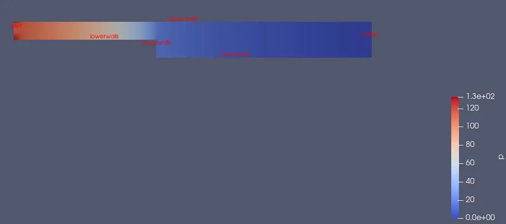
Uniform Velocity contour:
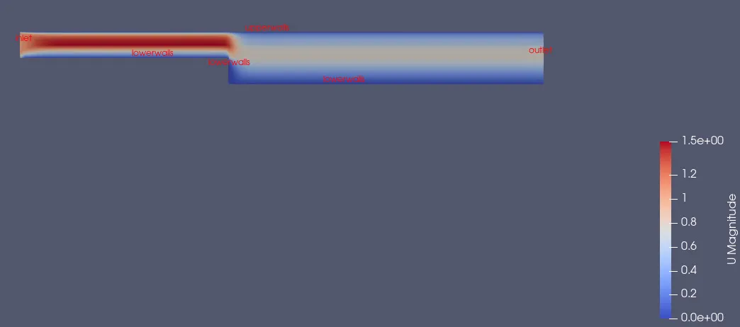
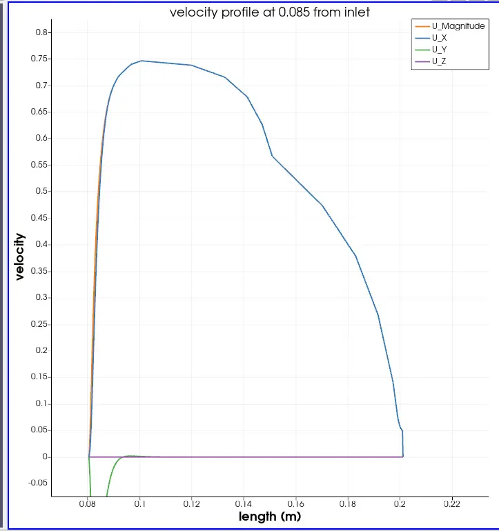
Here, at the end of the iterations the courant mean value is 0.35054 and max up to 1.578
And, the initial velocity residuals along x direction are 0.00016599 and also the final residuals of velocity in x direction are 2.22369e-06 also the initial velocity in y-direction is 0.000626656 and final velocity in y-direction is 9.55157e-07.
And also, at the end of the stimulation the initial residual of pressure is 0.000165216 and the final residual of pressure is 8.10677e-07
Conclusion:
From the above observations, the change in grading factor results in the mesh elements size regulation at the walls, and also smoothens the velocity profiles at the walls.
From the above case 1 graph the velocity profile is smooth and in the case 2 graph some cured edges are between the walls.