Week 3 Challenge : CFD meshing on Turbocharger
AIM: To check the geometrical errors to make appropriate volumes to the given model (Turbocharger) and perform surfaca mesh with given Target length and Perform Volumetric mesh to the given model.
PROCEDURE:
- First, run the ANSA software and open the downloded ANSA file into it.
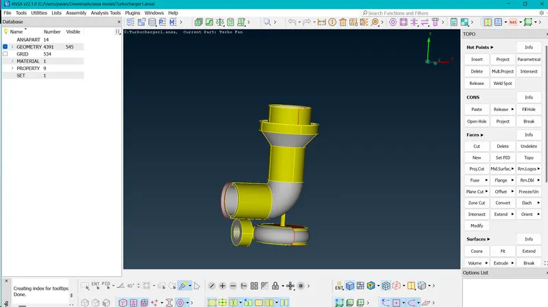
- Then check the geometrical errors by using CHECK option, and see the total single conc, triple cons present in the model.
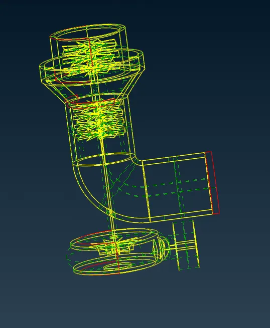
- First, solve the single cons in the model, there are some complex single con errors like the bottom surface.
- These, erors are resolved by inset hotpoints and using PARAMETRIC option and project new surface using NEW option in FACE section.
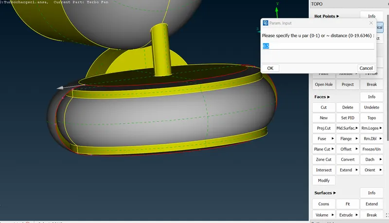
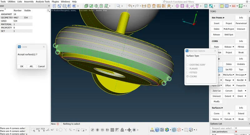
- hence finally the single cons are resolved and also solve the Triple cons which are not necessary.
- Remove the Triple cons, where the surfaces are overlaped by two surfaces and also use RELEASE and TOPO option to solve the errors.
- once we finish the, geomentrical errors checkup, the move to meshing part
- Before, mesh option i closed the opened surfaces like the inlet and outlet areas.
- Here, first define the PID's, to the respective model parts, and rename them as UPPER BLADE STAGE, MIDDLE BLADE PART, SHAFT ROTOR, TURBO CASING, IMPELLER, CASING INLET, COMPRESSOR CASING, CASING OUTLET, BOTTOM CASING INLET, BOTTOM CASING OUTLET.
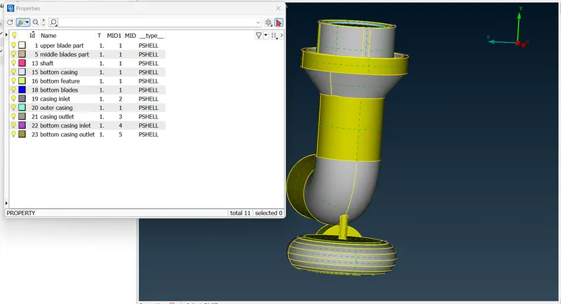
- Remove, the small unwanted surfaces, by inspecting every PID's.
- After, completing this move to MESH part and givee the Target lengths as per the given data
Blade stage-1 = 1 mm
Blade stage-2 = 1 mm
Impeller = 2 mm
Shaft rotor = 1 mm
Turbo casing = 5 mm
Compressor casing = 5 mm
Inlet casing cover = 5 mm - Mesh the respective PID's with respect to give Targe lengths.
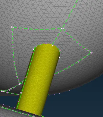
- Then create some cuts to separate the close meshed surface parts as shown in below fig.
- After, completing this, i moved to volumetric mesh, here the first step is to define the unmeshed areas using DEFINE tool and those are Auto detected by ANSA.
- Here, delete the unwanted unmeshed parts by considering the fluid flow and thickness of the model parts.
- Then the parts which we kept are remesh with TETRA CFD.
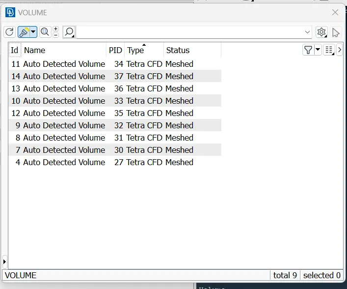
Hence, the volumeric mesh is done to the given model.
RESULTS: Hence i did the geomentrical checkup and Topomentric cleanup, and meshed the given model with given Targeted lengths, and performed Volumetric mesh.
COMPARISION: Here we se the variation in representation of shell trias in time of Meshing and i see volume Tetras after volumetic meshing, and also we can see the volumetric meshed surface by isolating the model.
CONCLUSION: I finally, comclude that the volumetric meshing tool mesh the volume of the model parts, based on the fluid flow and that volumetric elements are represented with tetra trio elements.