Week 3 - External flow simulation over an Ahmed body.
External flow simulation over an Ahmed body
AIM:-
To perform External flow simulation over an Ahmed body for velocity 25m/sec, and perform Grid independency test and also provide the velocity, pressure and coefficient of drag and lift with various cases.
THEORY:-
Q1. Describe Ahmed's body and its importance.
The Ahmed body is a simplified vehicle model. The airflow around the Ahmed body captures the essential flow features around an automobile and was first defined and characterized in the experimental work of Ahmed. Although it has a very simple shape, Ahmed body allows us to capture characteristic features that are relevant to bodies in the automobile industry. This model is also used to describe the turbulent flow field around a car-like geometry. Once the numerical model in validated, it is used to design new models of the car. Ahmed body is made up of round front part, a moveable z slant plane i
n the rear of the body to study the detachment phenomena at different angles, and a rectangular box which link the front part and the rear slant plane. The standard dimensions of the ahmed's model is shown as below
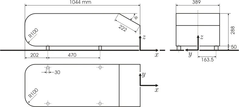
Importance of Ahmed body:
An Ahmed body represents a simplified like vehicle volume which helps understand the fundamental physics defining by the engineers the lift and drag forces and coefficients at certain characteristically velocities, pressure differences, and seeing and analyzing the vortices, turbulence and Reynolds number obtained. By performing theis type of stimulation gives the numerical results under validated conditions, and by comparing these results with experimental data used to Design new model of cars.
Q2. Explain the reason for the negative pressure in the wake region.
 \
\
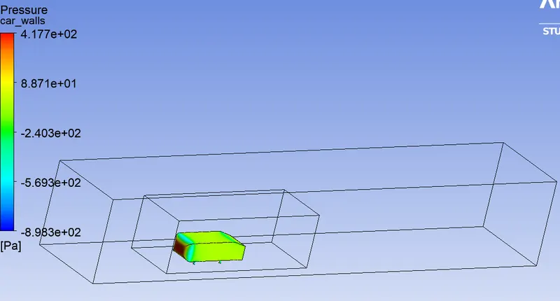
Here, the pressure difference occurs due to differnce in velocity at the rear portion of the model when stimulaton consideraconsidered at a low Reynolds number case, and due to this the pressure drops with gradually increasing the drag force that cause to generation of vortices at the Rear angle portion.
Q3. Explain the significance of the point of separation.
The point of separation by the Ahmed's body defines the direction of flow, the velocity of the flow, drag force at the certain point of the flow, the pressure difference and also defines the change of Reynolds number.
PROCEDURE:-
First, open the Ansys GUI and select the Fluid flow (fluent) tool and double-click on the Geomentry to open the Space-claim tool.
Geometry
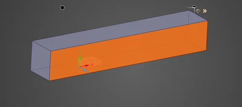
Then open the given ahmed's model into the spaceclaim. Now to enhance the Baseline mesh on the outside surface of the model use ENCLOSURE tool. And here the enclosure dimension setup should be
- The front face should be 5m long from the Front face of the model along the x-axis.
- The rear face should be 1m long from the rear face of the model along the x-axis.
- And the top face of the enclosure is at a distance of 1m from the top face of the body along Y- axis.
- The bottom face of the enclosure and the bottom face of the model has 0m distance, so they bottom face intersect each other.
- And the side faces are at a disttance of 0.5m along the Z-axis from the sides faces of the Ahmed's body.
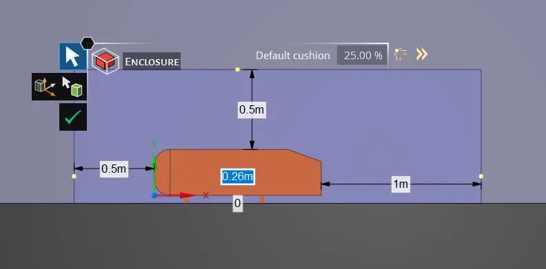
To refine the mesh inside the Enclosure instead of meeshind the whole doomine we need to create a Inner enclosure to the model, this is usually called Local Refinement. For this we shosetup the inner enclosure dimensions as
- The front face is located at a distance of 1 m from the frount face of the model along x-axis.
- And the rear face is located at a distance of 0.5m from the rear face of the model along tne x-axis.
- And the side faces are located at a distance of 0.26m from the side faces of the Ahmed's body along z-axis.
- And the Top face is is located at a distance of 0.5 m from the top face of the model along Y-axis.
- And the bottom face of the enclosure and the bottom face of the model intersect each other along the Y-axis.
After that, create plans by taking the origin as reference to visualize the meshing view. And create hatches to the side plane, and remove the unnecessary interference in the plane hatches because the mesh gets overlaps' between the outer and inner enclosures and also share the topology between the Enclosures.
Then, close the Geometry tool and now move on to the Meshing part, Now open the geometry in the meshing window.
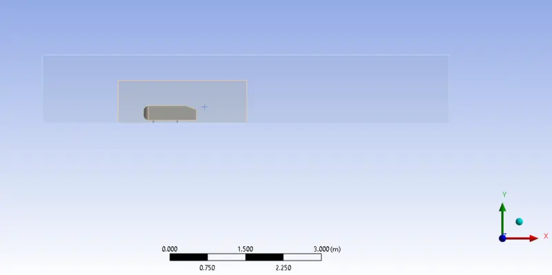
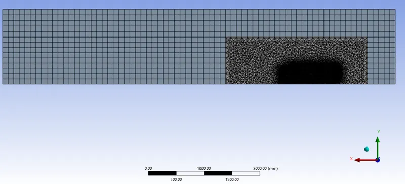
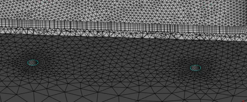
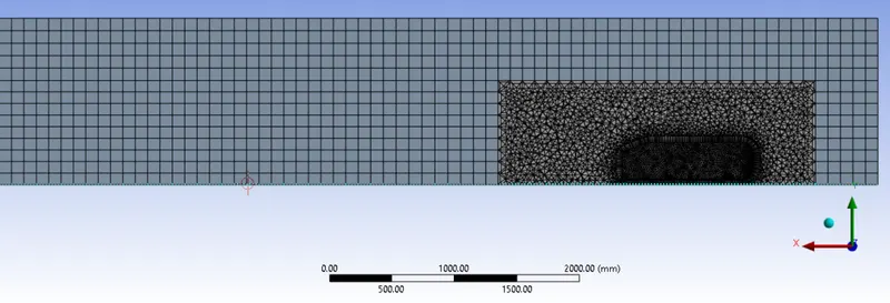
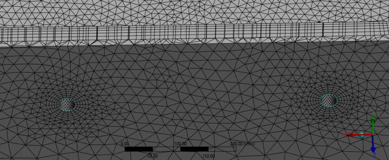
In the Grid independency test the outer Enclosure is meshed by tetrahedral grid elements, and the inner enlosure is meshed by hexahedral grid which need to be very fine to observe the flow structures, and also inflation layers are created along the walls of ahmed body to define the flow separation. To perform this the mesh elements sizes are varies in every case and the results are followed below in every case.
CASE 1:-
Now, create a Multizone meshing method to the outer body selection and set an element size of 100mm and also setup body sizing to the inner enclosure of element size of 50m, after that setup the face sizing to the ahmed body enclosure face with an element size of 20mm and apply a inflation layer to all faces of the named selection called Car-walls and apply an first layer height of 12.4mm
Hence, the Simulation was done for total no of mesh counts = 508907
where, outer box domain = 100mm size of hexahedral mesh
inner box domain = 50mm size of tetra mesh
face size of car wall domain = 10mm
and 5 inflation layer around the wall of ahmed body with Total thickness of first layer height of 24.87mm.
Now, close the mesh setup and open the meshed model into the setup solver and setup the viscous model to k-epsilon (2eqn) and also stimulate the model in steady time mode and pressure based solver, and aslo select the material as default air and its default properties.
Boundry conditions:
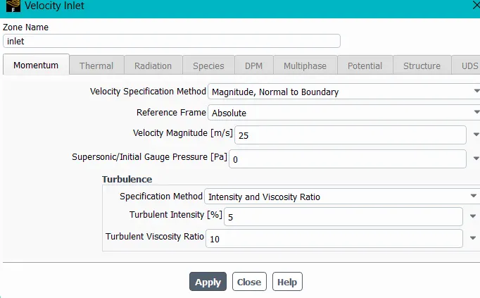
Now set the inlet velocity as 25 m/sec, and the walls of the Ahmed body should be no slipping and the oulet should be setup at gauge pressure as 0 pas.
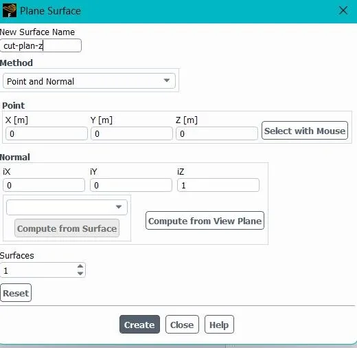
After that create a cut plane along the z-axis to monitor the stimulation, so create a point to normal plane and set the point to origin and normal to the z-axis
Then Create a new velocity and pressure conture to the cut plane z and also create a solution animation to observe the velocity stimulation on the cut plane and also create a drag coefficient and lift coefficient to the Ahmed's body surface.
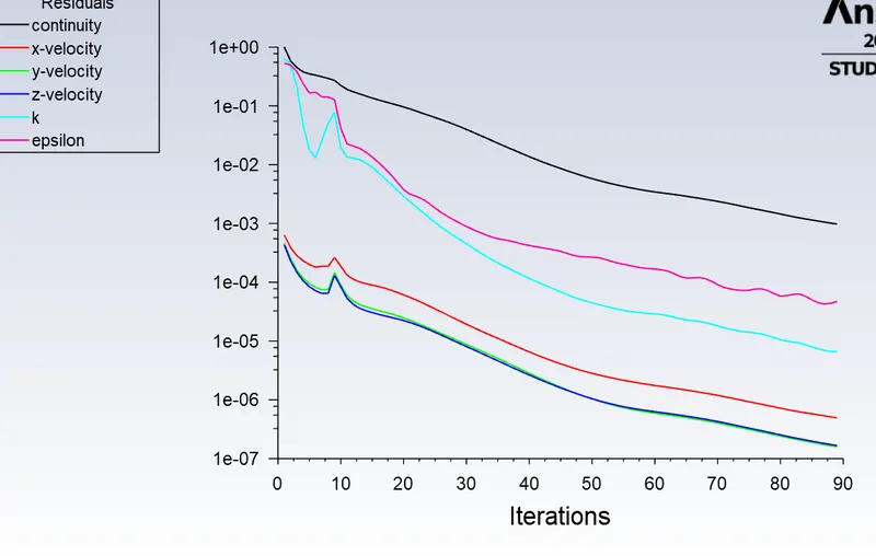
Residuals:
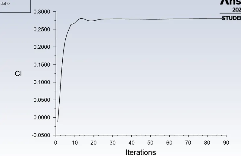
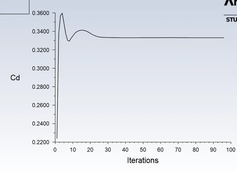
coefficient of Drag:
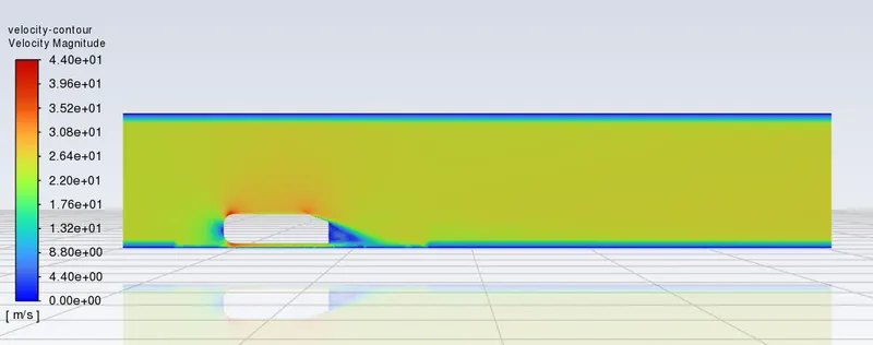
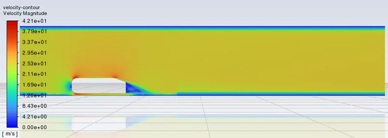
velocity contour plot:
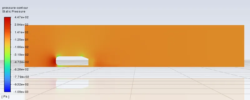
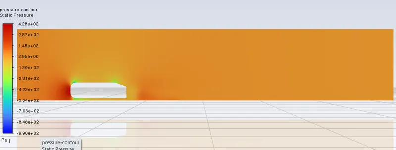
pressure contour plot:
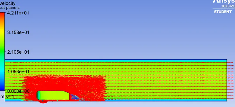
velocity-vector plot:

CASE 2:-
Hence, the Simulation was done for total no of mesh counts = 325339
where, outer box domain = 100mm size of hexahedral mesh
inner box domain = 50mm size of tetra mesh
face size of car wall domain = 15mm
and 5 inflation layer around the wall of ahmed body with Total thickness of 49.76mm
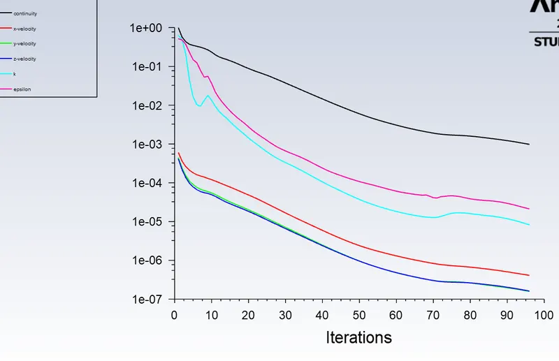
Residuals:
coefficient of Drag:
velocity contour plot:
pressure contour plot:
velocity-vector plot:
RESULTS AND CONCLUSION:
| Number of elements | drag co-efficient(Cd) | Lift co-efficient(Cl) |
| 508907 |
0.33309871 |
0.25438731 |
| 279527 |
0.34913895 |
0.27992848 |
Here, we observe that the baseline model mesh is not able to capture the external flow stimulation results. So we refined the meshing of the model upto the element size of outer enclosure 100mm and the face size of car wall domain 5mm results more than 510000 elememt cell , beyond that ANSYS solvent can't load the elemnts number more than 510000 under Academic licence, So the the outer enclosure of element size less than 0.1m can't be meshed using Academic licence.
And the velocity and flow stimulatons for every refinement are shown in above case study. Here, the pressure difference occurs due to differnce in velocity at the rear portion of the model when stimulaton consideraconsidered at a low Reynolds number case, and due to this the pressure drops with gradually increasing the drag force that cause to generation of vortices at the Rear angle portion. And also we observe the maximum velocity occured at case 1 where the mesh is very fine and also from the velocity vector plot the flow at the rear face of the body is hitting back and forming pressure gradient that also effects the drag force of the flow.