Week 4 Challenge : CFD Meshing for BMW car
AIM: To check and solve all geometrical errors on half portion and Assign appropriate PIDs to the given model and Perform meshing with the given Target length and element Quality criteria, After meshing the half model, Do symmetry to the other side, then create a wind tunnel to the model.
PROCEDURE:
- First, load the model into the GUI.
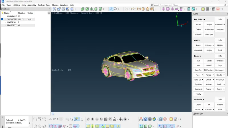
- Then see the sufaces, and i notice that there are some uneven surfaces present on the model, so simply i used surface mesh with length of 1mmm throught the model, that results all the perimeters of the model with equal length of 1mm, so my model surfaces looks even.
- Next to simplfy my process of topogrify i use symmetry option to my model. so i delete my half portion of my model in the top view mode, because i can simply symmetry the half portion into the other side of the surface.
- Then i started solving the single cons and triple cons on the every part surface of the model.
- so first i solved the single cons and triple cons on the Grills portion surface by using TOPO tools. And cleared all the topological errors on the Grill surface.
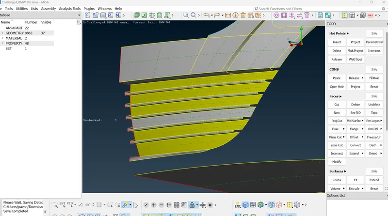
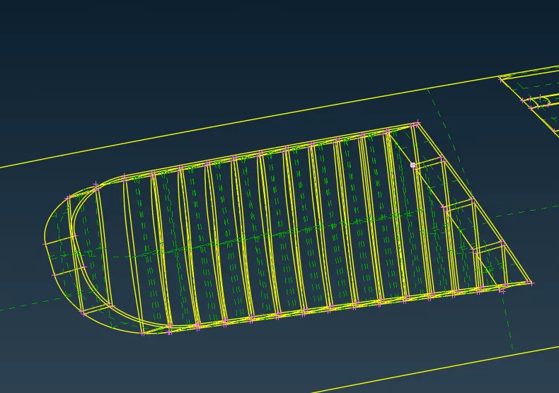
- so finally completed the all the Grills portion by removing all the single and triple cons.
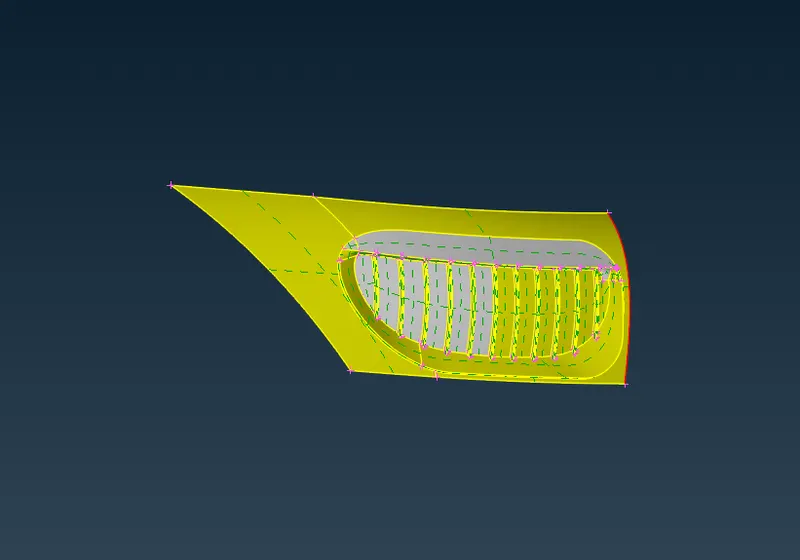
- Similarly, i did the same steps to solve the topological errors of the remaining parts means to the RIM and TIRES, LOGO, OPTICAL REARVIEW MIRROR, LIGHTS, and BODY surfaces.
- And here the main concept that we should follow is maintain a common volume inside the model, that means remove the individual volumes of the different parts, and maintain only a single volume to the model.
- After that remove the small areas that can cause error while meshing, to do this measure the distance between the cons and nodes and delete the cons which are with a small distance.
- After the completion of topological cleanup, define the PID's and assign the the PID's to the respective surfaces.
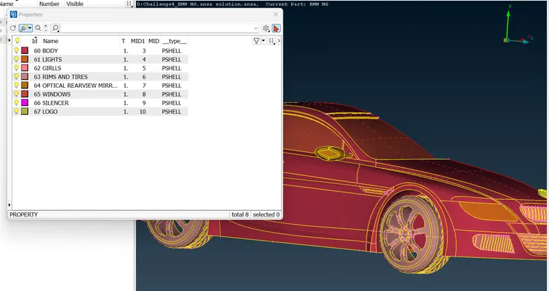
- After, assigning the PID's then i moved to meshing part.
- Here, i enable the openform quality criteria options and enable the following criteria options.
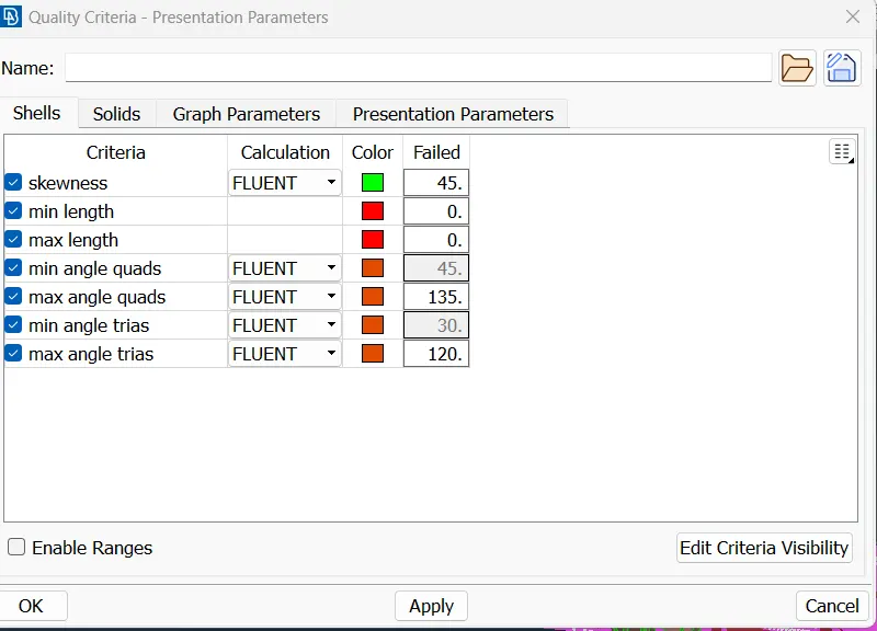
- Then follow the meshing steps, that first give the target length and quality criteries then give the perimeter and macro lengths to the defined PID's, as per given data.
Body - 3 mm
Lights - 4 mm
Grills - 1 mm
Rims and Tyres - 2 mm
Optical Rear view mirror - 2 mm
Window - 2 mm
Silencer - 3 mm
Logo - 1 mm - Then, after meshing a specific PID, move to HIDDEN mode and switch to ENT here i see the quality criteries are showing with different colours, and also off elements are also showing in this mode.
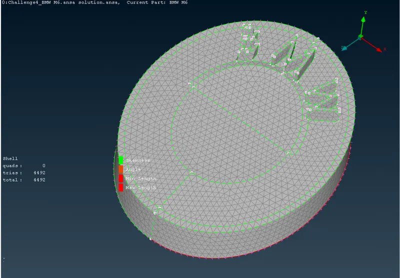
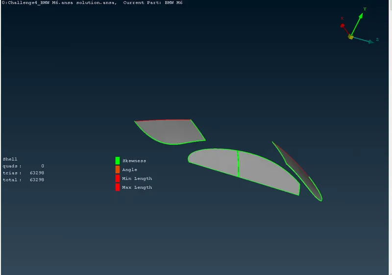
- So there errors are solved my switching to topo mode and solve the surface free from unwanted hotpoints and cons. And also MOVE tool to move the nodes to adjust the lenght of the elements. And also use PASTE option to paste a node on another. And also use RECONSTRUCT option to reduce the off elements.
- By, these tools i solved the meshing part to all the PID's and cleared all the off elements of the given model.
- Then, after completing the meshing part, project the solved part to the opposite side using SYMMETRY option then copy the defined part to the another side by mirrors of 3 points mode.
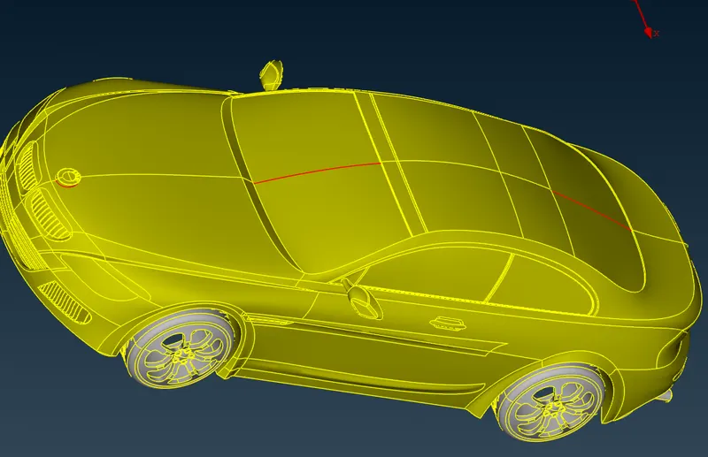
- And, here i noticed some single cons and by sing PASTE option i pasted those single cons and turn them to double cons.
- Then use CHECK option to see the geometric errors of the model.
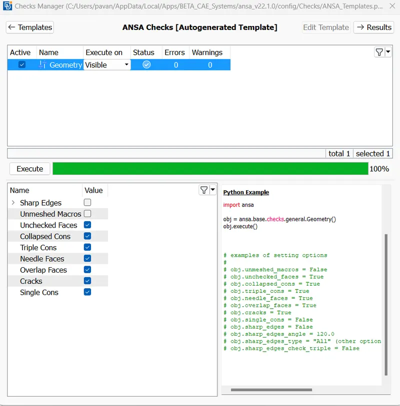
- Here all the errors are resolved. Then i started to make the wind tunnel to the given model.
- Here first measure the length of the model that treat as X=1307.8.
- And i inserted the POINTS --> RELATIVE at distance of 4X from the front and rear facing of the model, and also insert side point at a distance of X from the center part of the model and the Top and Bottom points should be at a distance of 3X from the center.
- After that use CURVES option and make a plane between the points that we inserted.
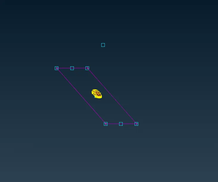
- By this, make all the faces by using CURVES option and make the surfaces of the Wind tunnel. Use NEW option to make planes to the cuurves.
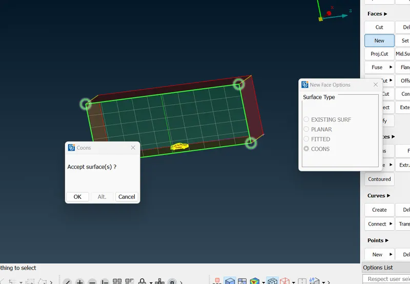
- Ater than assign the PID's to the faces to the wind tunnel and name the PID's as TOPSURFACE, REARSURFACE, SIDESURFACE, BASESURFACE. aND ASSIGN the PID'S.
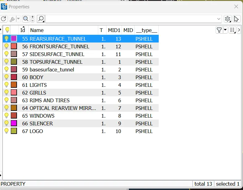
- Then mesh the TOP and bottom Surfaces using a Target length 100 and 20, then mess the sufaces of target lendth 100 and 20, then start meshing.
- Use SPACING INPUT tool and mesh the Frony and rear surfaces with a min limit of 20 and max limit to 100 with a spacing factor of 1.1
- also mesh the side surfaces. Then the final model looks like as follows.
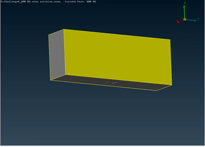
- Then moveon to volumetric meshing, here define the volumetric sufaces of the model.
- And delete the unwanted volumes and remesh the remaining volumes to Tetra CFD elements.
RESULTS: Hence finally, performed the meshing of windtunnel to the given BMW model, by performing topological cleanup and surface meshing opertations.
LEARNING OUTCOMES: By this session i learnt about the making of windtunnel and also learnt about some topological tools and meshing tools and tools that use to solve off elments, and effects of minnor lengths on meshing and effects of off elements while meshing and some meshing techniques all these concepts practised from this session.