Week 9: Project 1 - Surface preparation and Boundary Flagging (PFI)
Aim: To perform surface preparation and boundary flagging (PFI) to the given IC engine model by using Converge-CFD.
Objectives:
- perform surface preparation and Boundary flagging to the given model
- setting up the no hydro case set up.
- show the animation of mesh by showing the valves and piston should move according to the crank angles.
Description:
The given Ic_engine model contains intake and exhaust ports and valves and cylinder regions. The cylinder portion contains piston and spark terminal, to burn the fuel, and this cylinder region is set up with fuel injection system and exhaust system. This whole setup is work by crank operation.
Procedure:
Geometry cleanup:
Import the given model into converge GUI.
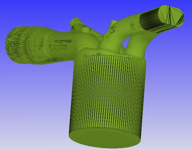
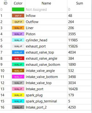
After, that flag the boundaries to the respective boundary regions.
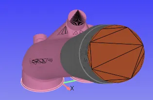
Inflow boundary:
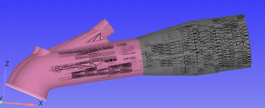
Intake port 1 and 2:
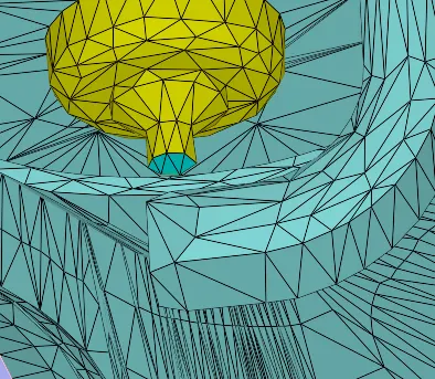
Here, the intake port is separated as Intale_port_1 and Intake_port_2. By using the boundary fence tool, the boundaries are flagged separately.
Outflow boundary:
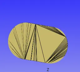
Exhaust port:
The entire exhaust port is flagged as exhaust port boundary.
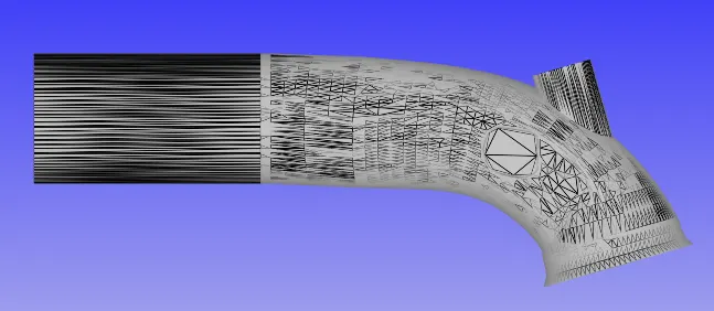
Liner:
The liner is the cylinder outer wall surface boundary.
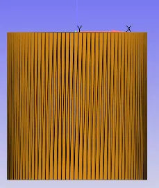
Piston:
And the piston head surface is flagged as the piston boundary.
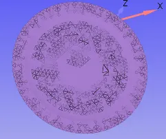
Cylinder head:
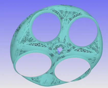
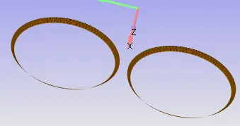
Exhaust valve top, bottom and valve angle:
The exhaust valve top, bottom, and valve angle surface are separated by using boundary fences and then flagged respectively.
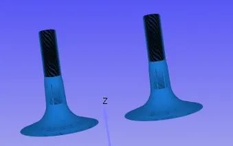
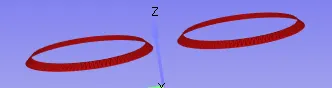
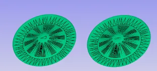
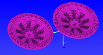
Intake valve top, bottom, and angle:
The intake valve top, bottom, and valve angle surface are separated by using boundary fences and then flagged respectively.
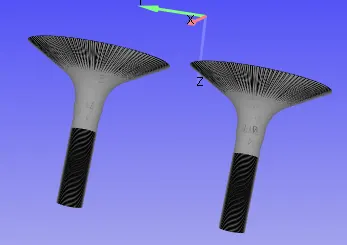
Spark plug:
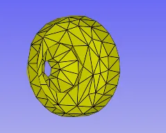
Spark plug terminal:
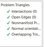
After, flagging the boundaries, check the diagnosis tool to identify the geometry errors like intersection, nonmanifold errors, normal orientation errors and so on. And here the diagnosis results no geometry errors.
Case setup:
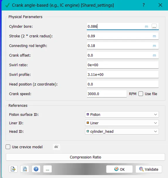
Application type: Crank angle -based
Here, the physical parameters of our ic_engine model are specified.
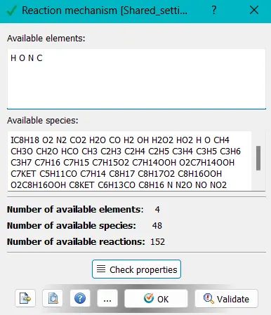
Reaction mechanism:
The given mech.dat data file is imported into here, and
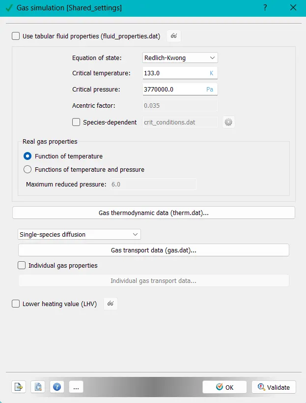
Gas simulation:
Here, the default values are taken under consideration.
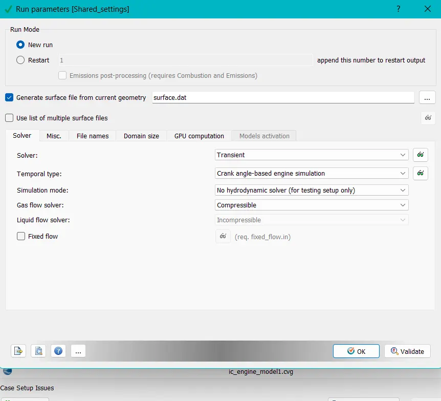
Run parameters:
This case setup is solving under Transient solver, under no hydrodynamic solver simulation mode.
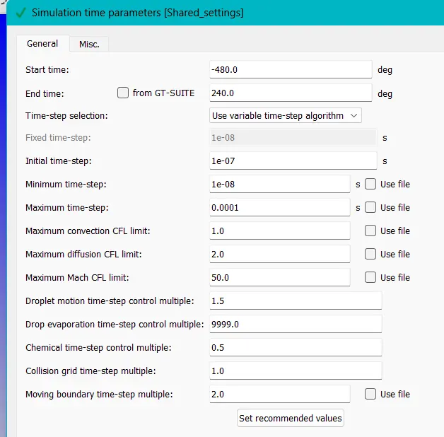
Simulation time parameters:
Solver parameters:

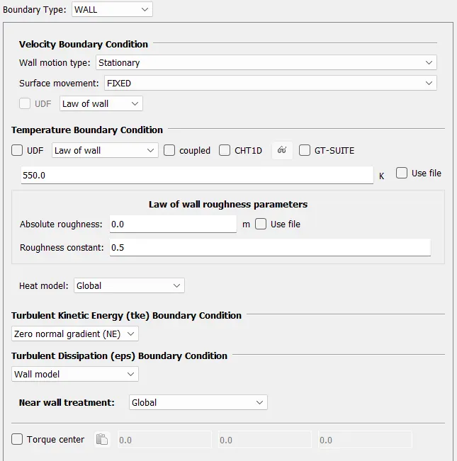
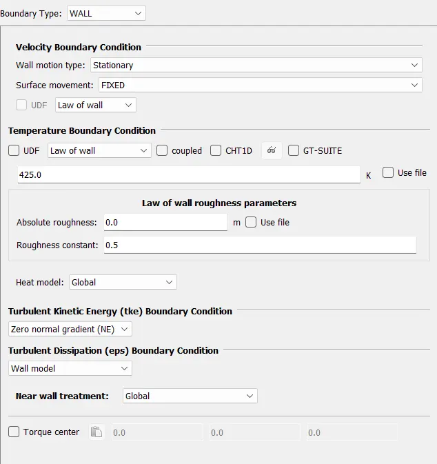
Boundary:
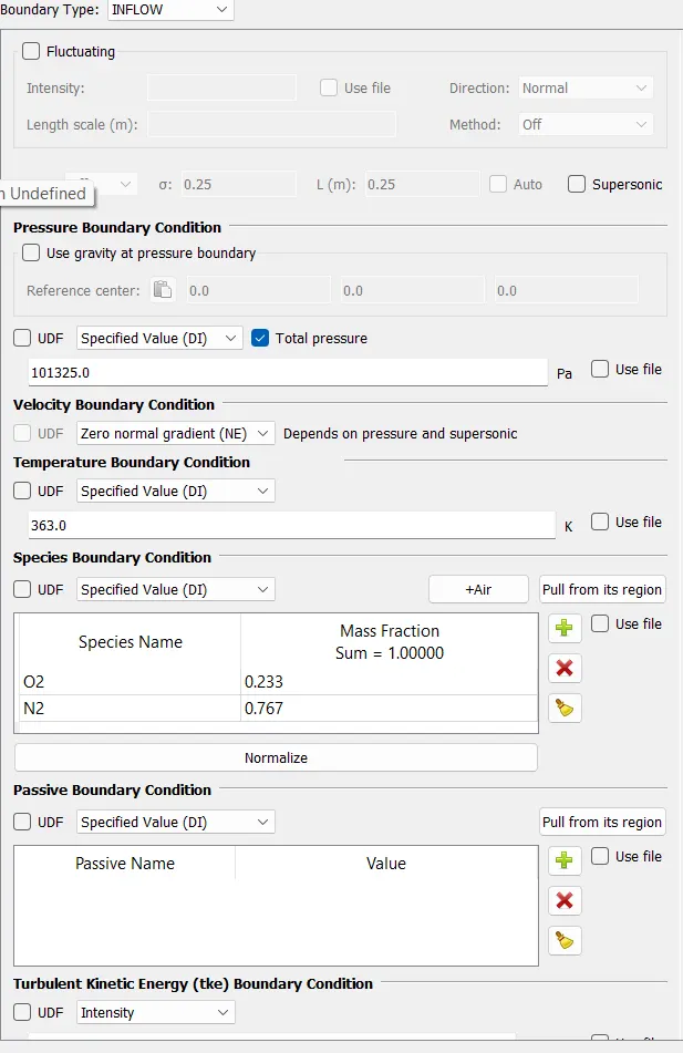
Inflow: region --> intake_port-2
Outflow: region --> Exhaust
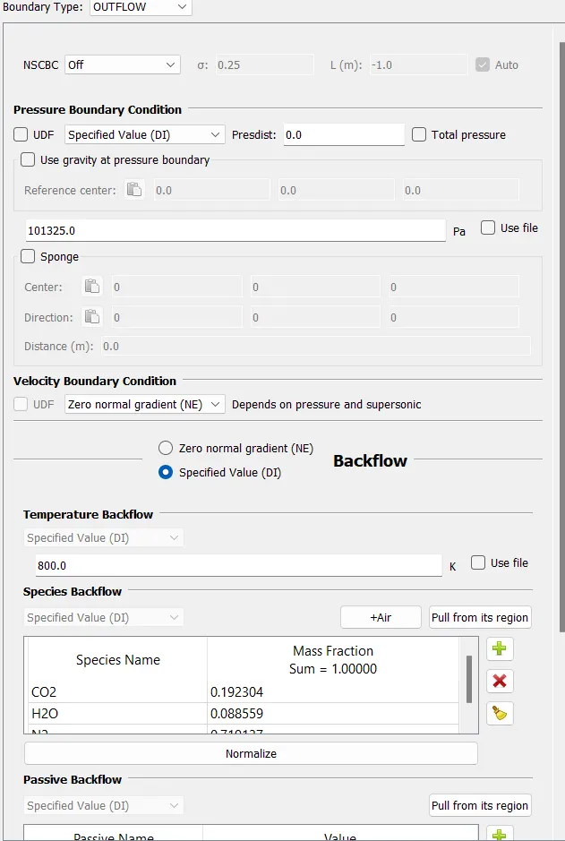
Liner: region --> cylinder
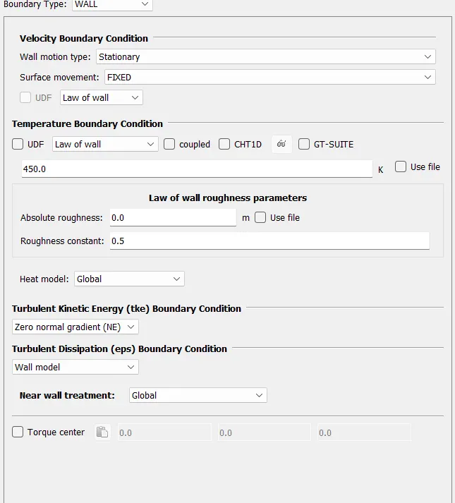
Piston: region--> cylinder
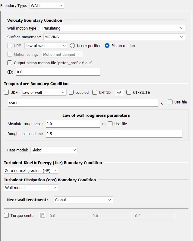
Cylinder head: region--> cylinder
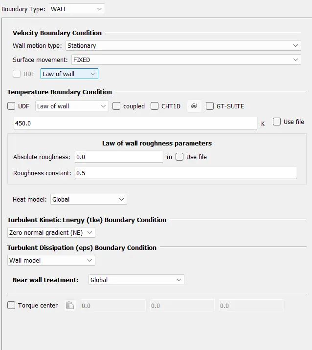
Exhaust port: region--> exhaust
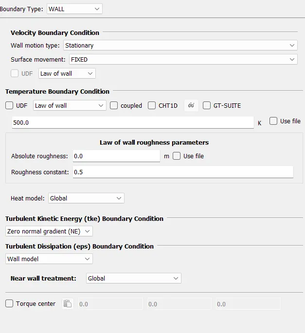
Exhaust valve top, angle: region --> exhaust
Exhaust valve bottom: region --> cylinder
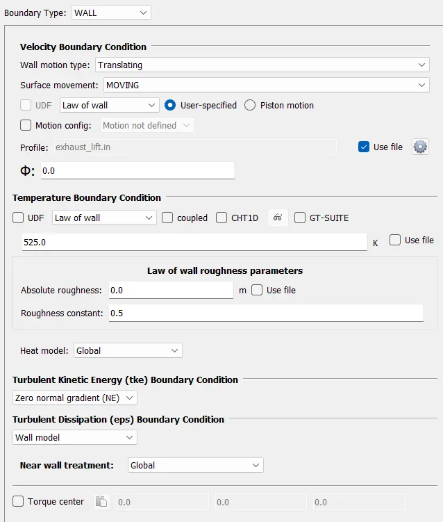
Intake valve angle, top: Region --> intake port-1
intake valve bottom: region --> cylinder
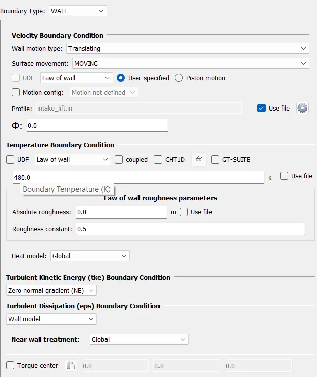
Intake port: region --> intake port-1
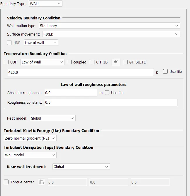
spark plug and terminal : region --> cylinder
Intake port-2: region --> intake port -2
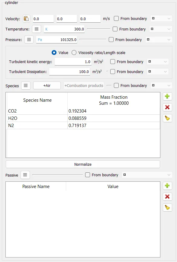
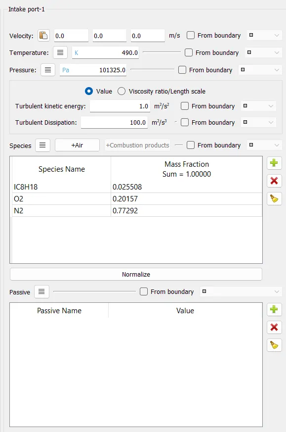
Regions and intialization:
cylinder:
Intake port-1:
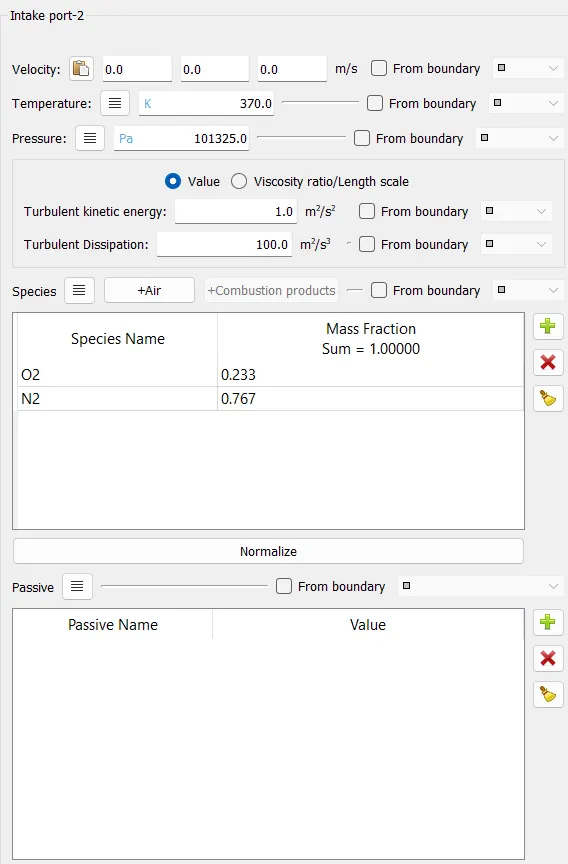
Intake port-2:
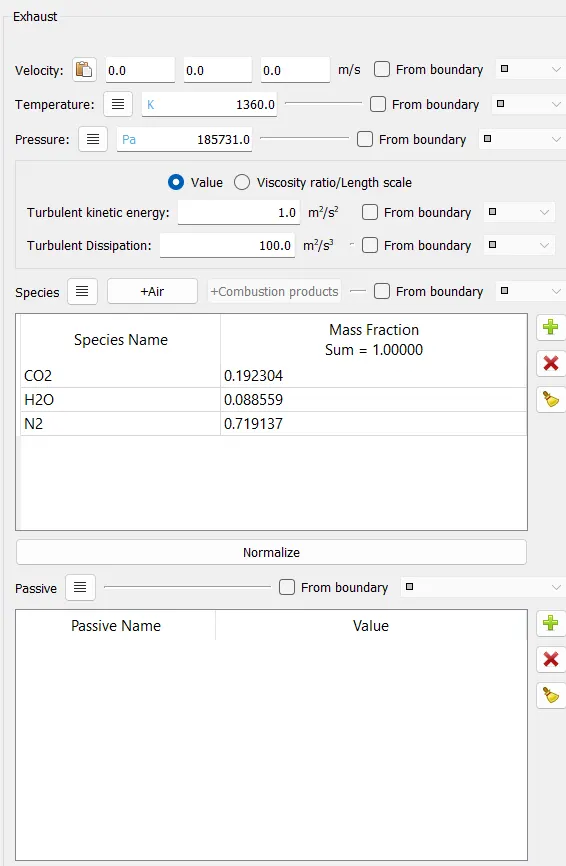
Exhaust:
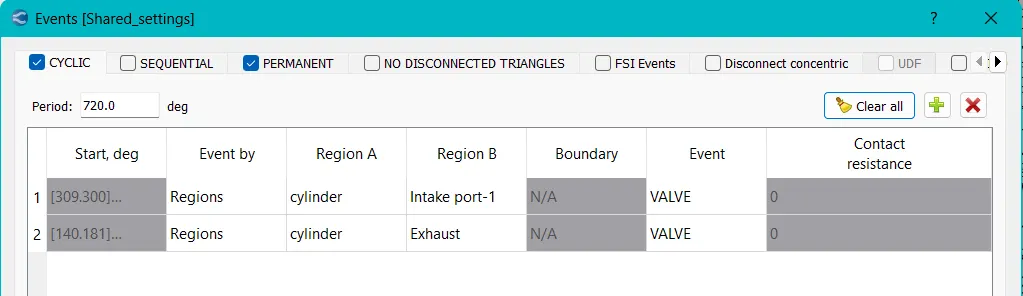
Events:
Cyclic:
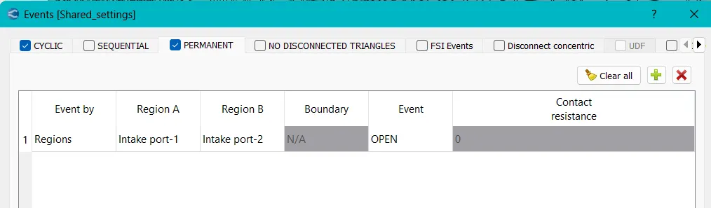
Premanent:
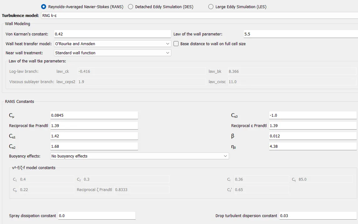
Turbulence modeling:
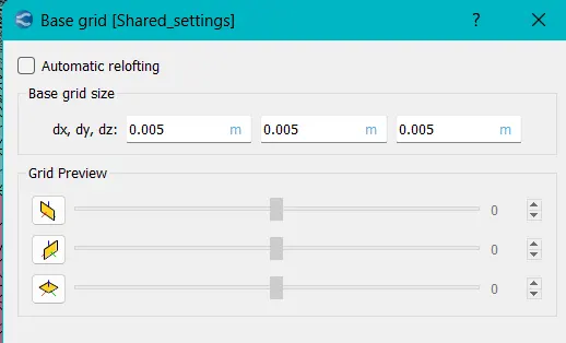
Base Grid:
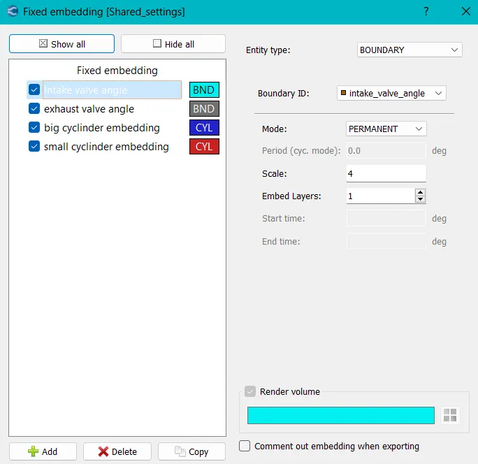
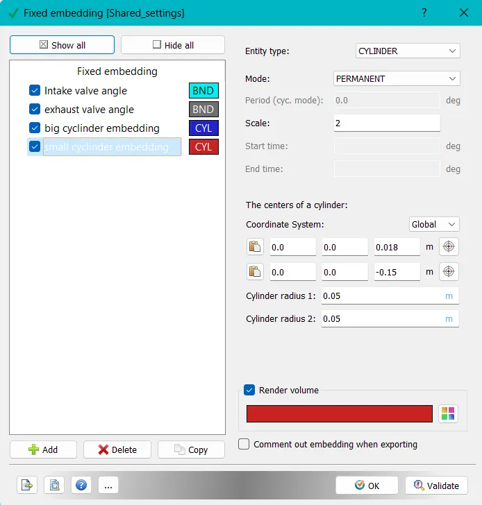
Fixed Embedding:
Intake valve angle and exhaust valve angle:
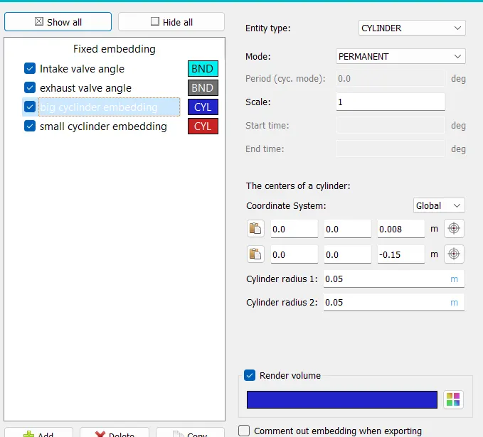
Big cylinder embedding:
Small cylinder embedding:
Output files:
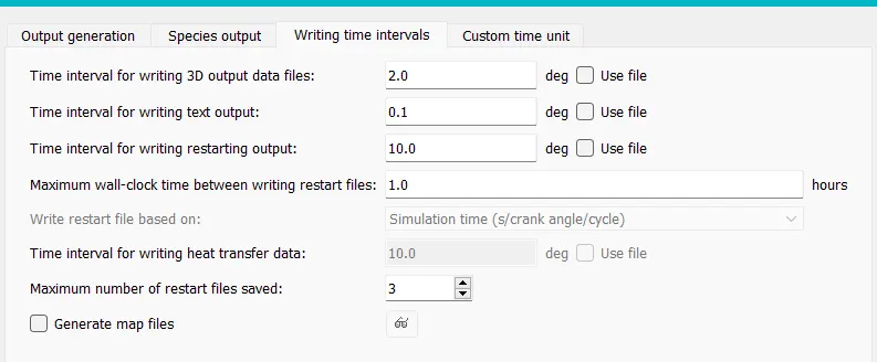
After validating the case set up, the input files are exported into the test case folder (File --> Export --> Export input files).
Running the Simulation:
- Open cygwin and navigate into the case directory where we exported the case setup input files.
- Run the following command
$ mpiexec -n 4 converge --license explore - This commands checks the license and converges the test case and generates output files.
- The to post process the results in Paraview, the output files are converted into group file format that supports in paraview.
- Then load the converted file into paraview to post process the results.
Post-Processing:
Animation results of Mesh generation: https://youtu.be/X_BRwasb4A4
Animation results of Pressure contour: https://youtu.be/o_KHEZKK35s
Conclusion:
Here, we performed the surface preparation and boundary flagging (PFI) to the given IC engine model by using Converge-CFD under no-hydro simulation setup and post processed the mesh results and valve moments in an animated file.