Week 6 - CHT Analysis on a Graphics card
AIM: To Perform a steady-state conjugate heat transfer analysis on a model of a graphics card by using appropriate materials of the simulation.
PROCEDURE:
Spaceclaim Geometry:
- Open the Spaceclaim tool and import the given downloaded Graphics card model.
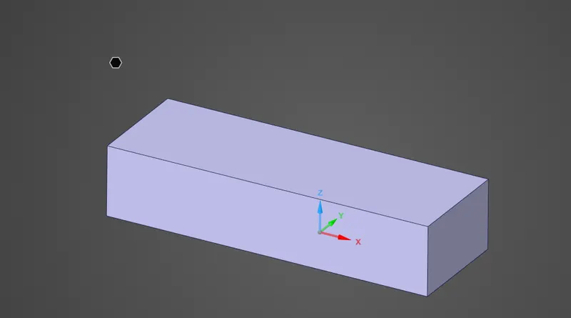
Graphics card Geomentry: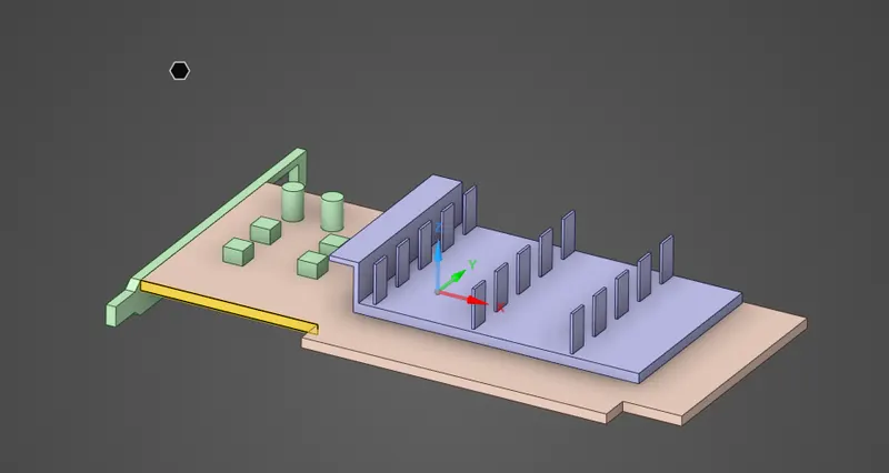
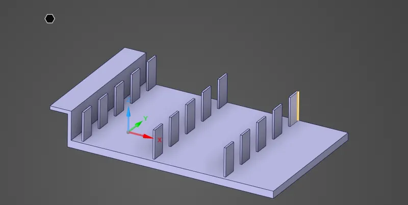
Fins Base:
Processor:
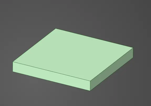
Base:
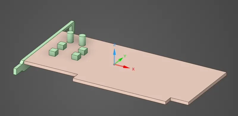
- And set the topological setup to share between the different components of the model.
-
CASE 1:
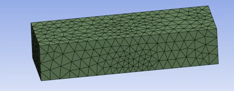
Then mesh the Baseline model with default mesh elment size and generate the mesh to the model. And it looks like as below fig. Here the defaults mesh formed 65478 number elements, and 14517 number nodes.
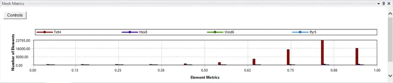
And the mesh Metric Quality of the model is mentioned below which looks less than 10%.
Stimulation setup:
-
Solver type: Steady state
- Type: Pressure based
- Turbulence model: k-Omega(SST)
- Materials: Different materials are selected to the different parts respectively as below
Parts Material Enclosure air Fin Aluminum Base steel Processor Titanium - Material Properties:
Air: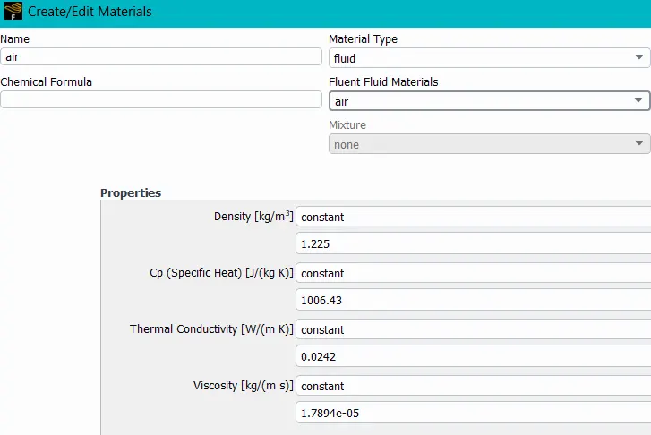
Steel: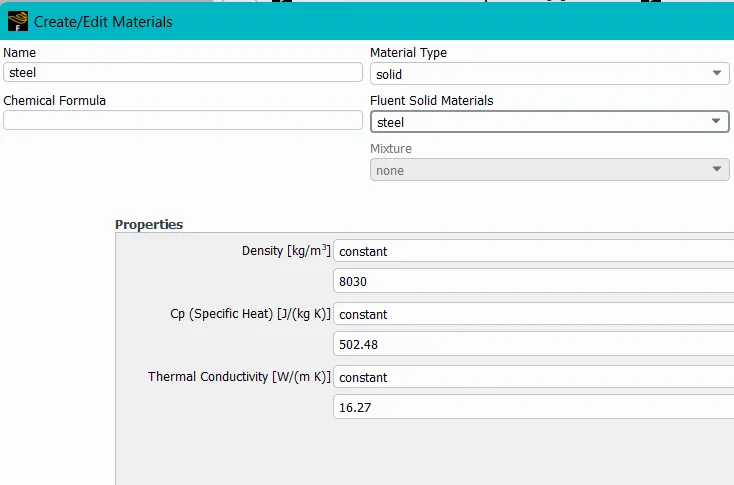
Aluminium: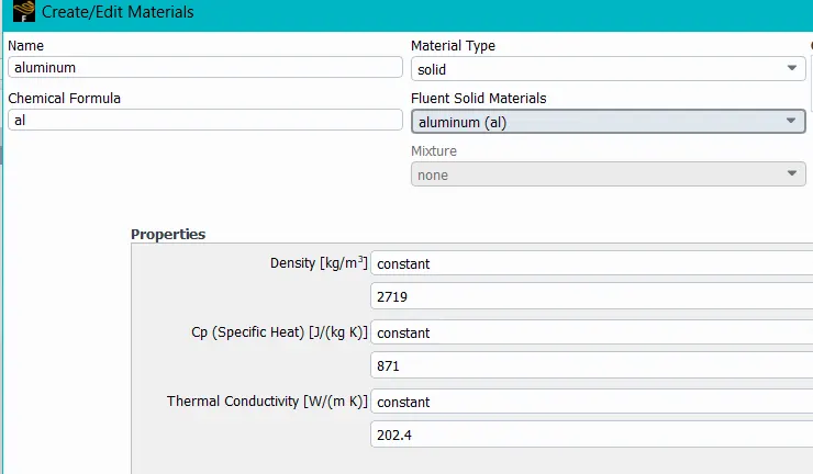
Titanium: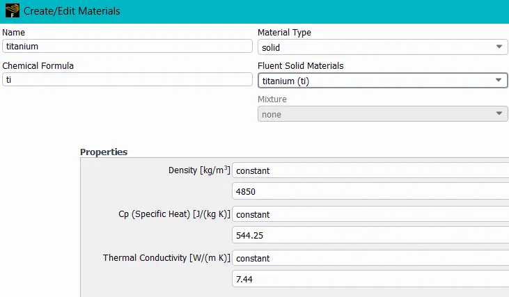
- Boundry conditions:
inlet:
Type: Velocity - inlet
Velocity: 5m/sec
Temperature: 300k
Outlet:
Type: Pressure - outlet
Pressure: 0 Pa
Temperature: 300k
Symmetry: Symmetry
Wall: Wall - Cell zones:
Enclosure: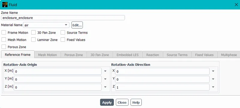
Fins: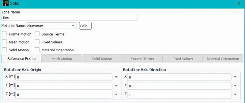
Base: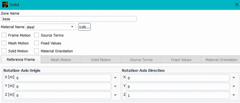
Processor:
let us calculate the Heat generatred by the Processure by assuming the input power as (P) 65watts and also volume of the model (V) as 8*8*1 mm^3.
so Heat Generated = P/V = 1015.62 W/m^3.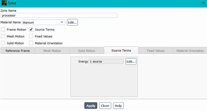
- After, setup the input data run the standed stimulation upto 500 interations and the output results are mentioned below.
Residuals: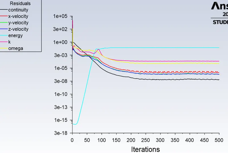
Temperature contour: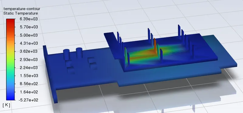
wall heat-transfer-coefficent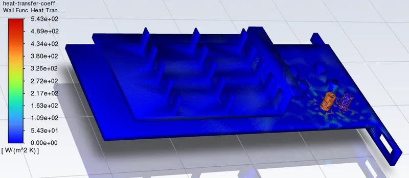
- Temperature of processor : 1009.755 K
- wall heat transfer coefficient: 4.2918932 W/(m^2 K)
- temperature of base: 661.44792 k
- wall heat transfer coefficient: 42.957291 W/(m^2 K)
- temperature of fins: 468.43402 k
- wall heat transfer coefficient: 37.315839 W/(m^2 K
-
CASE 2: Refined Mesh
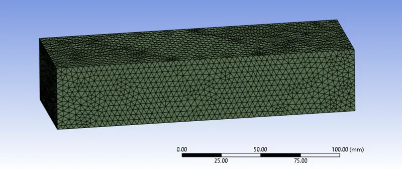
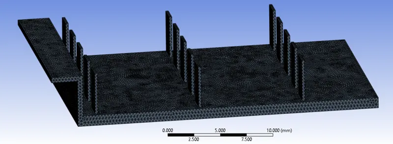
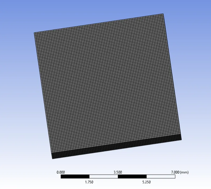
Now, refine the mesh in different regions with a refined elememt size as shown below.
Enclosure body - 3.3mm
Fine - 0.3mm
Base - 0.6mm
Processor - 0.1mmThen, the refined meshed models are generated with 495104 number elements and 164038 number nodes are the meshing results are mentioned below.
Enclosure:
Fine:
Base:
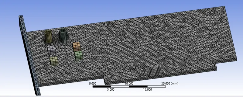
Processor:

- Boundry conditions 1:
inlet:
Type: Velocity - inlet
Velocity: 1 m/sec
Temperature: 300k
Outlet:
Type: Pressure - outlet
Pressure: 0 Pa
Temperature: 300k
Symmetry: Symmetry
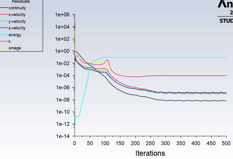
Wall: Wall - Residuals:
Temperature contour: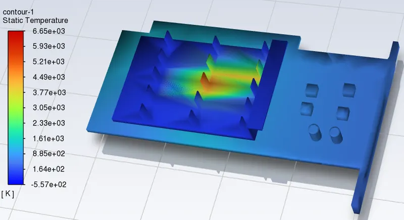
Wall heat transfer coefficient: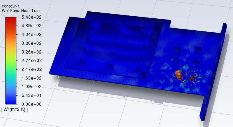
- Temperature of processor :1732.1331 K
- wall heat transfer coefficient: 5.4615749 W/(m^2 K)
- temperature of base: 495.62191k
- wall heat transfer coefficient: 30.80317 W/(m^2 K)
- temperature of fins: 1032.4743 k
- wall heat transfer coefficient: 37.380825 W/(m^2 K
velocity contour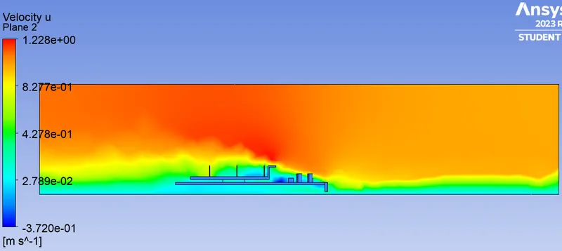
- Boundry conditions 2:
inlet:
Type: Velocity - inlet
Velocity: 3 m/sec
Temperature: 300k
Outlet:
Type: Pressure - outlet
Pressure: 0 Pa
Temperature: 300k
Symmetry: Symmetry
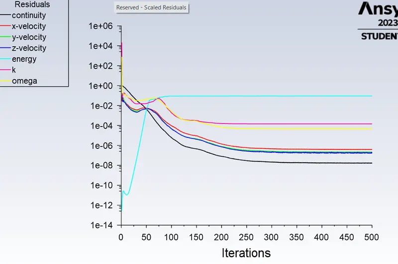
Wall: Wall - Residuals:
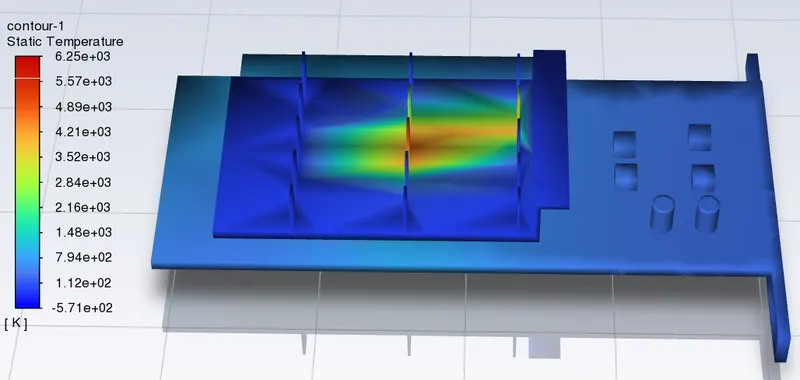
Temperature contour:
Wall heat transfer coefficient:
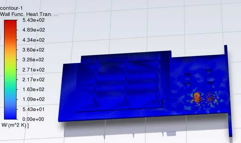
- Temperature of processor : 1451.2472 K
- wall heat transfer coefficient: 5.8151634 W/(m^2 K)
- temperature of base: 474.35361 k
- wall heat transfer coefficient: 34.088707 W/(m^2 K)
- temperature of fins: 729.5296 k
- wall heat transfer coefficient: 40.400327 W/(m^2 K)
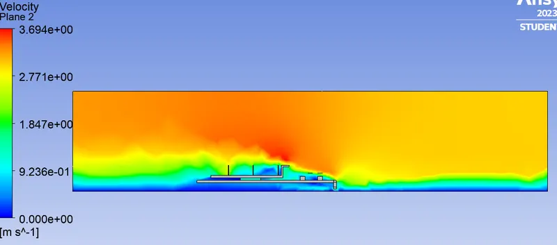
velocity contour:
- Boundry conditions 3:
inlet:
Type: Velocity - inlet
Velocity: 5 m/sec
Temperature: 300k
Outlet:
Type: Pressure - outlet
Pressure: 0 Pa
Temperature: 300k
Symmetry: Symmetry
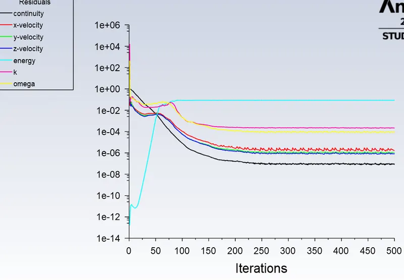
Wall: Wall - Residuals:
Temperature contour: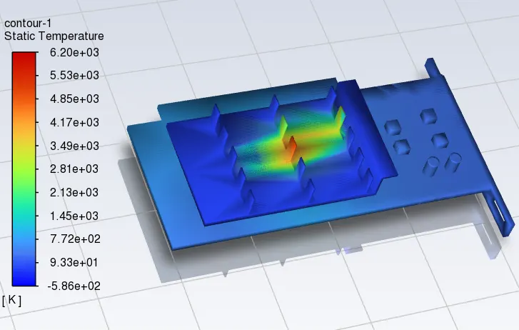
Wall heat transfer coefficient: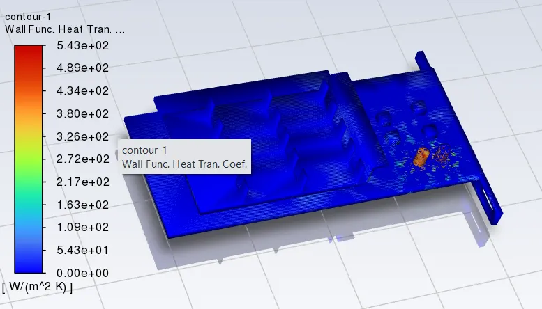
- Temperature of processor :1421.2933K
- wall heat transfer coefficient: 6.4399 W/(m^2 K)
- temperature of base: 471.06993 k
- wall heat transfer coefficient:37.319275 W/(m^2 K)
- temperature of fins: 682.21635 k
- wall heat transfer coefficient: 42.968 W/(m^2 K)
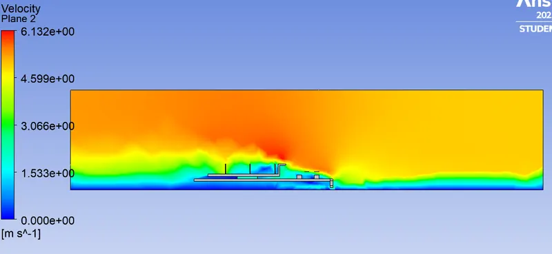
- velocity contour:
CONCLUSION:
The model is successfully stimulated by using ANSYS Fluent under Acedemic license limits with differnt input conditions.
The maximum temperature and heat transfer coefficient attained by the processor, Fin, of Baseline and refined models at varies velocities are Base are shown below.
| Baseline at 5 m/sec | Refined model at 1 m/sec | Refined model at 3 m/sec | Refined model at 5 m/secc | |
| maximum Temperature (k) | 1009.755 | 1732.133 | 1451.2472 | 1421.293 |
| maximum Heat Transfer Coefficent W/(m^2 K) | 42.9572 | 37.38082 | 40.4003 | 42.968 |
Here, from the Residual ploting results in all cases are results as repetitive plots, we can conclude that the model is convergenced. Here the Processor acts as the power sorce input.
Here, the baseline model is refined with minimum element size that results increase in the number of elements that are generated unnder Acedemic licence limits.
And also we observe that the maximum Temperature is raised at the Processor surface in all different input cases. And based on the assigned materials properties also the stimulation results are generated. And also we observe that the increase in velocity input the temperature raised on the components surface are gradually decresed. So we conclude that the higher velocities acts as a coolent. Here covection is occurs when generated heat is removed by the inlet air flow and Conduction occurs when the generated heat is transferred from the proceeser to the adjacent parts.