Week 12 - Validation studies of Symmetry BC vs Wedge BC in OpenFOAM vs Analytical H.P equation
Objective: simulation of flow through pipe.
- To validate hydro-dynamic length with the numerical result.
- To validate the fully developed flow velocity profile with its analytical profile.
- To validate maximum velocity and pressure drop for fully developed flow.
- To post process shear stress and validate wall shear stress for fully developed flow.
- To highlight the difference in both boundary condition in terms of their usage and application.
MATLAB code to create blockMeshDict file
With wedge boundary conditions
close all; clear all;clc;

%% define diameter,angle and length of the pipe
D=0.01;  r=D/2;      L=2;
theta=input('enter the wedge angle ');
%% file parsing
f1 = fopen('blockMeshDict','w');


fprintf(f1,'%s \n','/*--------------------------------*- C++ -*----------------------------------*\');
fprintf(f1,'%s \n',' =========                 |');
fprintf(f1,'%s \n','  \\      /  F ield         | OpenFOAM: The Open Source CFD Toolbox');
fprintf(f1,'%s \n','   \\    /   O peration     | Website:  https://openfoam.org');
fprintf(f1,'%s \n','    \\  /    A nd           | Version:  10');
fprintf(f1,'%s \n','     \\/     M anipulation  |');
fprintf(f1,'%s \n','\*---------------------------------------------------------------------------*/');


fprintf(f1,'%s \n','FoamFile');
fprintf(f1,'%s \n','{');
fprintf(f1,'\t %s \n','format      ascii;');
fprintf(f1,'\t %s \n','class       dictionary;');
fprintf(f1,'\t %s \n','object      blockMeshDict;');
fprintf(f1,'%s \n','}');
fprintf(f1,'// * * * * * * * * * * * * * * * * * * * * * * * * * * * * * * * * * * * * * //\n');
fprintf(f1,'convertToMeters %d;\n',1);

fprintf(f1,'%s \n','vertices');
fprintf(f1,'%s \n','(');

fprintf(f1, '\t(%d %d %d)\n',0,0,0);
fprintf(f1, '\t(%d %f %f)\n',0,r*cosd(theta/2),r*sind(theta/2));
fprintf(f1, '\t(%d %f %f)\n',0,r*cosd(-theta/2),r*sind(-theta/2));
fprintf(f1, '\t(%d %d %d)\n',L,0,0);
fprintf(f1, '\t(%d %f %f)\n',L,r*cosd(theta/2),r*sind(theta/2));
fprintf(f1, '\t(%d %f %f)\n',L,r*cosd(-theta/2),r*sind(-theta/2));
fprintf(f1,'%s \n',');');


fprintf(f1,'%s \n','blocks');
fprintf(f1,'%s \n','(');
fprintf(f1, '\t hex (%d %d %d %d %d %d %d %d)(%d %d %d)',0,3,5,2,0,3,4,1,500,40,1);
fprintf(f1,' simpleGrading (%d %f %d)\n',1,0.2,1);
fprintf(f1,'%s \n',');');

fprintf(f1,'%s \n','edges');
fprintf(f1,'%s \n','(');
fprintf(f1, '\t arc %d %d (%d %f %d)\n',1,2,0,r,0);
fprintf(f1, '\t arc %d %d (%d %f %d)\n',4,5,L,r,0);
fprintf(f1,'%s \n',');');


fprintf(f1,'%s \n','boundary');
fprintf(f1,'%s \n','(');

fprintf(f1,'\t %s \n','inlet');
fprintf(f1,'\t %s \n','{');
fprintf(f1,'\t \t %s \n','type patch;');
fprintf(f1,'\t \t %s \n','faces');
fprintf(f1,'\t \t %s \n','(');
fprintf(f1, '\t \t \t (%d %d %d %d)\n',0,1,2,0);
fprintf(f1,'\t \t %s \n',');');
fprintf(f1,'\t %s \n','}');

fprintf(f1,'\t %s \n','outlet');
fprintf(f1,'\t %s \n','{');
fprintf(f1,'\t \t %s \n','type patch;');
fprintf(f1,'\t \t %s \n','faces');
fprintf(f1,'\t \t %s \n','(');
fprintf(f1, '\t \t \t (%d %d %d %d)\n',3,4,5,3);
fprintf(f1,'\t \t %s \n',');');
fprintf(f1,'\t %s \n','}');

fprintf(f1,'\t %s \n','Axis');
fprintf(f1,'\t %s \n','{');
fprintf(f1,'\t \t %s \n','type empty;');
fprintf(f1,'\t \t %s \n','faces');
fprintf(f1,'\t \t %s \n','(');
fprintf(f1, '\t \t \t (%d %d %d %d)\n',0,3,3,0);
fprintf(f1,'\t \t %s \n',');');
fprintf(f1,'\t %s \n','}');

fprintf(f1,'\t %s \n','fixedWalls');
fprintf(f1,'\t %s \n','{');
fprintf(f1,'\t \t %s \n','type wall;');
fprintf(f1,'\t \t %s \n','faces');
fprintf(f1,'\t \t %s \n','(');
fprintf(f1, '\t \t \t (%d %d %d %d)\n',1,4,5,2);
fprintf(f1,'\t \t %s \n',');');
fprintf(f1,'\t %s \n','}');

fprintf(f1,'\t %s \n','Wedge1');
fprintf(f1,'\t %s \n','{');
fprintf(f1,'\t \t %s \n','type wedge;');
fprintf(f1,'\t \t %s \n','faces');
fprintf(f1,'\t \t %s \n','(');
fprintf(f1, '\t \t \t (%d %d %d %d)\n',0,3,5,2);
fprintf(f1,'\t \t %s \n',');');
fprintf(f1,'\t %s \n','}');

fprintf(f1,'\t %s \n','Wedge2');
fprintf(f1,'\t %s \n','{');
fprintf(f1,'\t \t %s \n','type wedge;');
fprintf(f1,'\t \t %s \n','faces');
fprintf(f1,'\t \t %s \n','(');
fprintf(f1, '\t \t \t (%d %d %d %d)\n',0,3,4,1);
fprintf(f1,'\t \t %s \n',');');
fprintf(f1,'\t %s \n','}');


fprintf(f1,'%s \n',');');


fprintf(f1,'%s \n','mergePatchPairs');
fprintf(f1,'%s \n','(');
fprintf(f1,'%s \n',');');
fprintf(f1,'%s','// ************************************************************************* //');
fclose(f1);

%% Analytical calculation
v_avg=0.21;
R=r; mu=0.0010016;
r_array=linspace(0,R,40);
v=2*v_avg*(1-(r_array.^2)/R^2);

figure(1)
plot(r_array,v);
xlabel('Pipe Radius(R)');
ylabel('Velocity profile');
title('Velocity profile for a fully developed flow along pipe radius');

for i=1:39
    tau(i+1)=mu*( (v(i+1)-v(i)) / (r_array(i+1)-r_array(i)) );
end
    figure(2)
    plot(r_array,tau);
    xlabel('Pipe Radius(R)');
    ylabel('Shear Stress profile');
    title('Shear Stress profile for a fully developed flow along pipe radius');

L_h=1.26;
L_fd=L-L_h;
deltaP=32*mu*v_avg*L_fd/(D^2);
L_fdarray=linspace(0,L_fd,200);
deltaP_array=linspace(deltaP,0,200);


figure(3)
plot(L_fdarray,deltaP_array);
xlabel('Length of the pipe(X axis)');
ylabel('Pressure');
title('Pressure drop for a fully developed flow along the length of the pipe');
blockMeshDict files
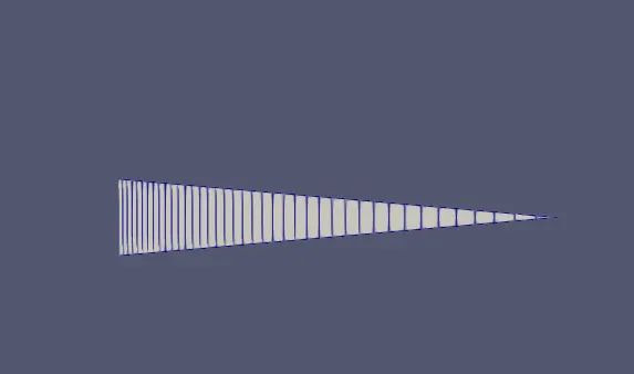
a) for 10 degree angle
/*--------------------------------*- C++ -*----------------------------------*\
 =========                 |
  \\      /  F ield         | OpenFOAM: The Open Source CFD Toolbox
   \\    /   O peration     | Website:  https://openfoam.org
    \\  /    A nd           | Version:  10
     \\/     M anipulation  |
\*---------------------------------------------------------------------------*/
FoamFile
{
	 format      ascii;
	 class       dictionary;
	 object      blockMeshDict;
}
// * * * * * * * * * * * * * * * * * * * * * * * * * * * * * * * * * * * * * //
convertToMeters 1;
vertices
(
	(0 0 0)
	(0 0.004981 0.000436)
	(0 0.004981 -0.000436)
	(2 0 0)
	(2 0.004981 0.000436)
	(2 0.004981 -0.000436)
);
blocks
(
	 hex (0 3 5 2 0 3 4 1)(500 40 1) simpleGrading (1 0.200000 1)
);
edges
(
	 arc 1 2 (0 0.005000 0)
	 arc 4 5 (2 0.005000 0)
);
boundary
(
	 inlet
	 {
	 	 type patch;
	 	 faces
	 	 (
	 	 	 (0 1 2 0)
	 	 );
	 }
	 outlet
	 {
	 	 type patch;
	 	 faces
	 	 (
	 	 	 (3 4 5 3)
	 	 );
	 }
	 Axis
	 {
	 	 type empty;
	 	 faces
	 	 (
	 	 	 (0 3 3 0)
	 	 );
	 }
	 fixedWalls
	 {
	 	 type wall;
	 	 faces
	 	 (
	 	 	 (1 4 5 2)
	 	 );
	 }
	 Wedge1
	 {
	 	 type wedge;
	 	 faces
	 	 (
	 	 	 (0 3 5 2)
	 	 );
	 }
	 Wedge2
	 {
	 	 type wedge;
	 	 faces
	 	 (
	 	 	 (0 3 4 1)
	 	 );
	 }
);
mergePatchPairs
(
);
// ************************************************************************* //
Paraview figure for after blockMesh command is shown below
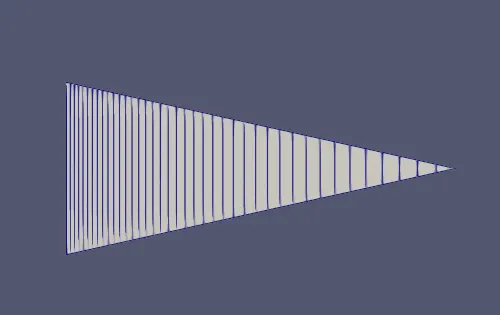
b) for 25 degree angle
/*--------------------------------*- C++ -*----------------------------------*\
 =========                 |
  \\      /  F ield         | OpenFOAM: The Open Source CFD Toolbox
   \\    /   O peration     | Website:  https://openfoam.org
    \\  /    A nd           | Version:  10
     \\/     M anipulation  |
\*---------------------------------------------------------------------------*/
FoamFile
{
	 format      ascii;
	 class       dictionary;
	 object      blockMeshDict;
}
// * * * * * * * * * * * * * * * * * * * * * * * * * * * * * * * * * * * * * //
convertToMeters 1;
vertices
(
	(0 0 0)
	(0 0.004881 0.001082)
	(0 0.004881 -0.001082)
	(2 0 0)
	(2 0.004881 0.001082)
	(2 0.004881 -0.001082)
);
blocks
(
	 hex (0 3 5 2 0 3 4 1)(500 40 1) simpleGrading (1 0.200000 1)
);
edges
(
	 arc 1 2 (0 0.005000 0)
	 arc 4 5 (2 0.005000 0)
);
boundary
(
	 inlet
	 {
	 	 type patch;
	 	 faces
	 	 (
	 	 	 (0 1 2 0)
	 	 );
	 }
	 outlet
	 {
	 	 type patch;
	 	 faces
	 	 (
	 	 	 (3 4 5 3)
	 	 );
	 }
	 Axis
	 {
	 	 type empty;
	 	 faces
	 	 (
	 	 	 (0 3 3 0)
	 	 );
	 }
	 fixedWalls
	 {
	 	 type wall;
	 	 faces
	 	 (
	 	 	 (1 4 5 2)
	 	 );
	 }
	 Wedge1
	 {
	 	 type wedge;
	 	 faces
	 	 (
	 	 	 (0 3 5 2)
	 	 );
	 }
	 Wedge2
	 {
	 	 type wedge;
	 	 faces
	 	 (
	 	 	 (0 3 4 1)
	 	 );
	 }
);
mergePatchPairs
(
);
// ************************************************************************* //
Paraview figure for after blockMesh command is shown below
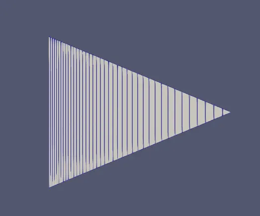
c) for 45 degree angle
/*--------------------------------*- C++ -*----------------------------------*\
 =========                 |
  \\      /  F ield         | OpenFOAM: The Open Source CFD Toolbox
   \\    /   O peration     | Website:  https://openfoam.org
    \\  /    A nd           | Version:  10
     \\/     M anipulation  |
\*---------------------------------------------------------------------------*/
FoamFile
{
	 format      ascii;
	 class       dictionary;
	 object      blockMeshDict;
}
// * * * * * * * * * * * * * * * * * * * * * * * * * * * * * * * * * * * * * //
convertToMeters 1;
vertices
(
	(0 0 0)
	(0 0.004619 0.001913)
	(0 0.004619 -0.001913)
	(2 0 0)
	(2 0.004619 0.001913)
	(2 0.004619 -0.001913)
);
blocks
(
	 hex (0 3 5 2 0 3 4 1)(500 40 1) simpleGrading (1 0.200000 1)
);
edges
(
	 arc 1 2 (0 0.005000 0)
	 arc 4 5 (2 0.005000 0)
);
boundary
(
	 inlet
	 {
	 	 type patch;
	 	 faces
	 	 (
	 	 	 (0 1 2 0)
	 	 );
	 }
	 outlet
	 {
	 	 type patch;
	 	 faces
	 	 (
	 	 	 (3 4 5 3)
	 	 );
	 }
	 Axis
	 {
	 	 type empty;
	 	 faces
	 	 (
	 	 	 (0 3 3 0)
	 	 );
	 }
	 fixedWalls
	 {
	 	 type wall;
	 	 faces
	 	 (
	 	 	 (1 4 5 2)
	 	 );
	 }
	 Wedge1
	 {
	 	 type wedge;
	 	 faces
	 	 (
	 	 	 (0 3 5 2)
	 	 );
	 }
	 Wedge2
	 {
	 	 type wedge;
	 	 faces
	 	 (
	 	 	 (0 3 4 1)
	 	 );
	 }
);
mergePatchPairs
(
);
// ************************************************************************* //
Paraview figure for after blockMesh command is shown below
Note:- All other files like controlDict,physical properties, U and p will be same for every angle which is given below.
U File
/*--------------------------------*- C++ -*----------------------------------*\
  =========                 |
  \\      /  F ield         | OpenFOAM: The Open Source CFD Toolbox
   \\    /   O peration     | Website:  https://openfoam.org
    \\  /    A nd           | Version:  10
     \\/     M anipulation  |
\*---------------------------------------------------------------------------*/
FoamFile
{
    format      ascii;
    class       volVectorField;
    object      U;
}
// * * * * * * * * * * * * * * * * * * * * * * * * * * * * * * * * * * * * * //

dimensions      [0 1 -1 0 0 0 0];

internalField   uniform (0 0 0);

boundaryField
{
    inlet
    {
        type            fixedValue;
        value           uniform (0.21 0 0);
    }
    outlet
    {
        type            zeroGradient;
    }
    Axis
    {
	 type            empty;
    }

    fixedWalls
    {
        type            noSlip;
    }

    Wedge1
    {
        type            wedge;
    }
    Wedge2
    {
        type            wedge;
    }

}

// ************************************************************************* //
P File
/*--------------------------------*- C++ -*----------------------------------*\
  =========                 |
  \\      /  F ield         | OpenFOAM: The Open Source CFD Toolbox
   \\    /   O peration     | Website:  https://openfoam.org
    \\  /    A nd           | Version:  10
     \\/     M anipulation  |
\*---------------------------------------------------------------------------*/
FoamFile
{
    format      ascii;
    class       volScalarField;
    object      p;
}
// * * * * * * * * * * * * * * * * * * * * * * * * * * * * * * * * * * * * * //

dimensions      [0 2 -2 0 0 0 0];

internalField   uniform 0;

boundaryField
{
    inlet
    {
        type            zeroGradient;
    }
   outlet
    {
        type            fixedValue;
	  value		uniform 0;
    }
    Axis
    {
        type            empty;
    }

    fixedWalls
    {
        type            zeroGradient;
    }
    Wedge1
    {
        type            wedge;
    }
    Wedge2
    {
        type            wedge;
    }

}

// ************************************************************************* //
ControlDict File
/*--------------------------------*- C++ -*----------------------------------*\
  =========                 |
  \\      /  F ield         | OpenFOAM: The Open Source CFD Toolbox
   \\    /   O peration     | Website:  https://openfoam.org
    \\  /    A nd           | Version:  10
     \\/     M anipulation  |
\*---------------------------------------------------------------------------*/
FoamFile
{
    format      ascii;
    class       dictionary;
    location    "system";
    object      controlDict;
}
// * * * * * * * * * * * * * * * * * * * * * * * * * * * * * * * * * * * * * //

application     icoFoam;

startFrom       startTime;

startTime       0;

stopAt          endTime;

endTime         10;

deltaT          0.002;

writeControl    timeStep;

writeInterval   20;

purgeWrite      0;

writeFormat     ascii;

writePrecision  6;

writeCompression off;

timeFormat      general;

timePrecision   6;

runTimeModifiable true;


// ************************************************************************* //
physical properties
/*--------------------------------*- C++ -*----------------------------------*\
  =========                 |
  \\      /  F ield         | OpenFOAM: The Open Source CFD Toolbox
   \\    /   O peration     | Website:  https://openfoam.org
    \\  /    A nd           | Version:  10
     \\/     M anipulation  |
\*---------------------------------------------------------------------------*/
FoamFile
{
    format      ascii;
    class       dictionary;
    location    "constant";
    object      physicalProperties;
}
// * * * * * * * * * * * * * * * * * * * * * * * * * * * * * * * * * * * * * //

nu              [0 2 -1 0 0 0 0] 1e-6;


// ************************************************************************* //
Paraview
a) for 10 degree angle
Velocity profile along the pipe length
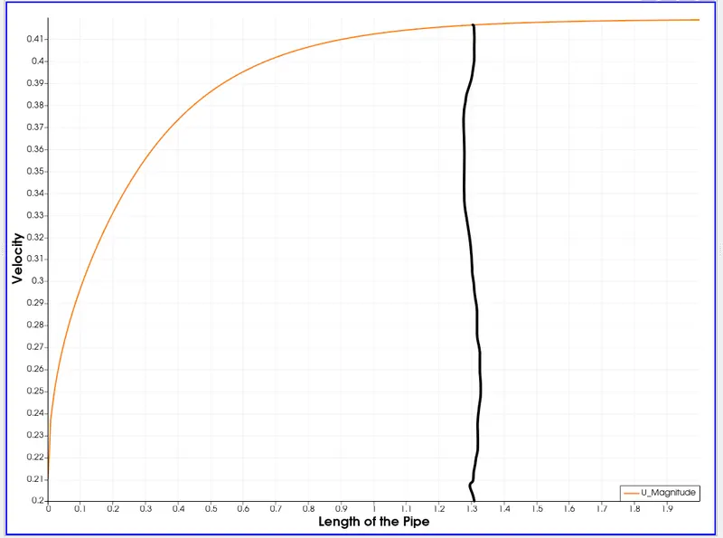
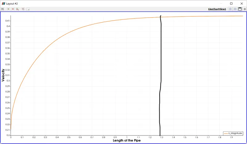
We observed that, that the fully developed velocity profile is around 1.30 m from inlet.
From analytical solution it is around 1.26 m from inlet.
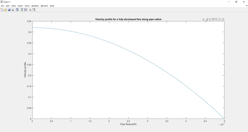
From the graph, we observed that the maximum velocity for a fully developed is double the average velocity. The average velocity is the inlet velocity of 0.21 m/s
The pressure drop profile alomng the length of the pipe is shown below
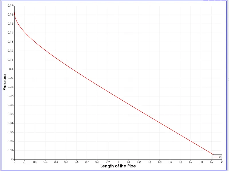
The pressure drop profile after fully developed is shown below
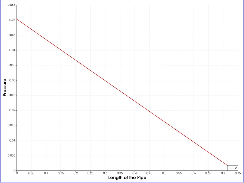
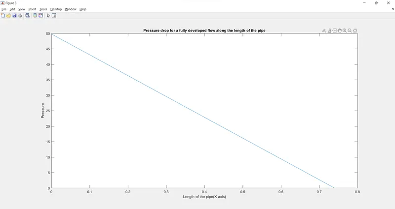
The pressure drop is also around 50 Pa which is close to the analytical value
The shear stress profile after fully developed is shown below
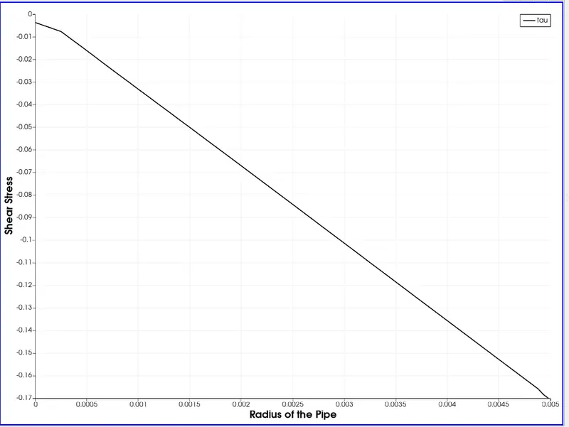
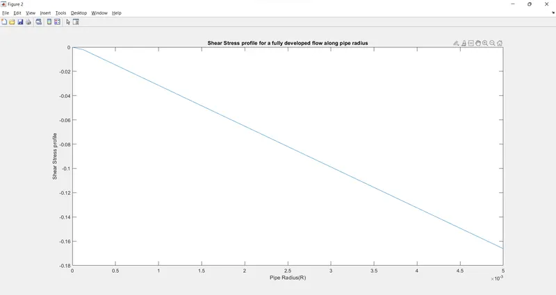
The maximum shear stress value obtained analytically is 0.1661 Pa. From Simulation, we got it nearly 0.169 Pa. so shear stress is validated
Velocity profiles at different sections from inlet
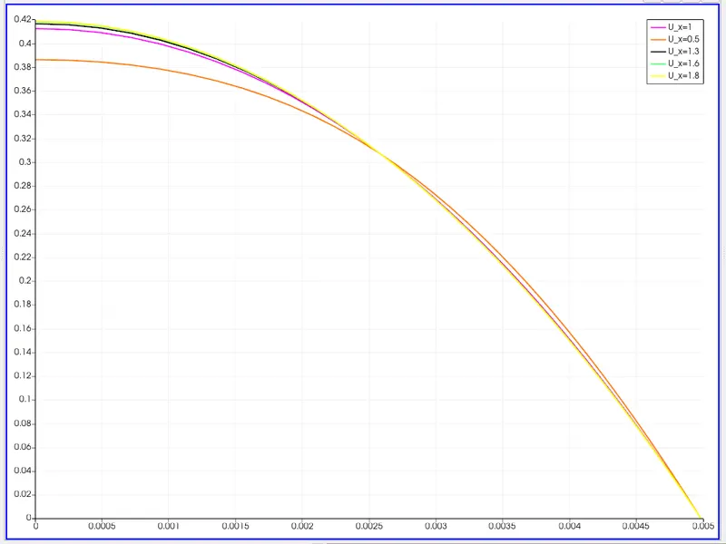
From the graph it is observed that at a distance of 1.6 m and 1.8 m, the velocity profiles overlap each other. This is a region of fully developed flow. The distance at 1.3 m also closely follows the line at 1.6 m and 1.8 m.
b) for 25 degree angle
Velocity profile along the pipe length
We observed that, that the fully developed velocity profile is around 1.30 m from inlet.
From analytical solution it is around 1.26 m from inlet.
From the graph, we observed that the maximum velocity for a fully developed is double the average velocity. The average velocity is the inlet velocity of 0.21 m/s
The pressure drop profile along the length of the pipe is shown below
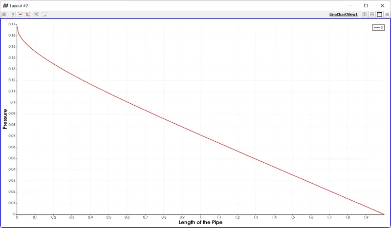
The pressure drop profile after fully developed is shown below
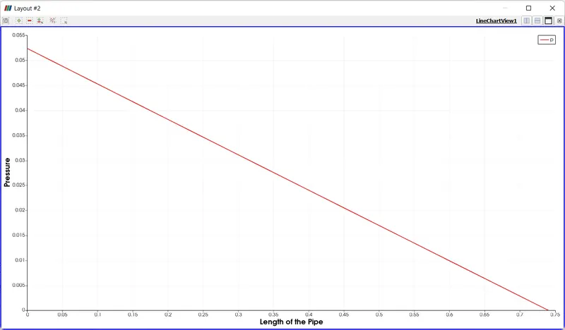
The pressure drop is also around 52 Pa which is close to the analytical value
The shear stress profile after fully developed is shown below
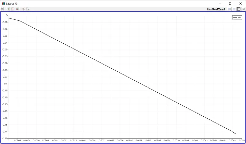
The maximum shear stress value obtained analytically is 0.1661 Pa. From Simulation, we got it nearly 0.173 Pa. so shear stress is validated. We observed this change from varying wedge angle
Velocity profiles at different sections from inlet
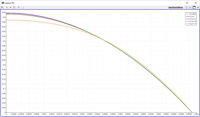
From the graph it is observed that at a distance of 1.6 m and 1.8 m, the velocity profiles overlap each other. This is a region of fully developed flow. The distance at 1.3 m also closely follows the line at 1.6 m and 1.8 m.
Also, it is observed that, the radius is not covered fully by y axis because we use 2 D simulation.
----------------------------------------------------============================================================
c) for 45 degree angle
Velocity profile along the pipe length
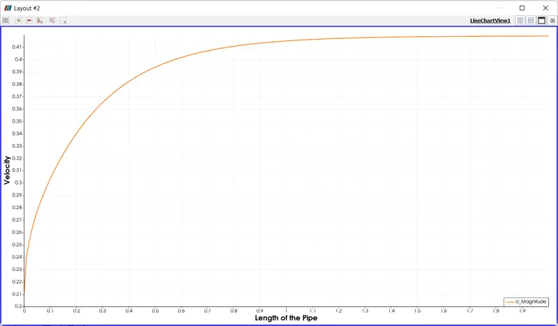
We observed that, that the fully developed velocity profile is around 1.30 m from inlet.
From analytical solution it is around 1.26 m from inlet.
From the graph, we observed that the maximum velocity for a fully developed is double the average velocity. The average velocity is the inlet velocity of 0.21 m/s
The pressure drop profile along the length of the pipe is shown below
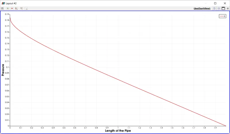
The pressure drop profile after fully developed is shown below
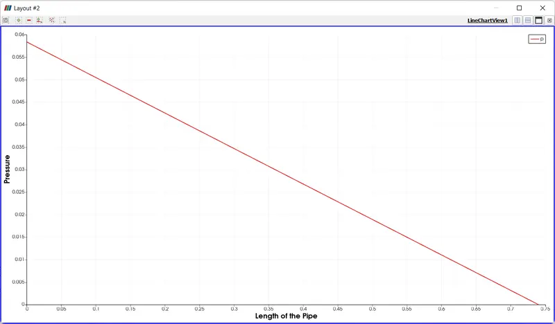
The pressure drop is also around 58 Pa which is close to the analytical value
The shear stress profile after fully developed is shown below
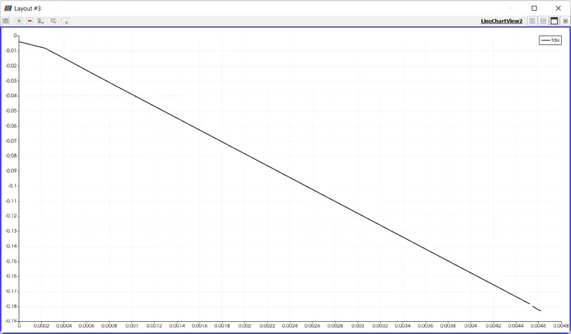
The maximum shear stress value obtained analytically is 0.1661 Pa. From Simulation, we got it nearly 0.173 Pa. so shear stress is validated. We observed this change from varying wedge angle
Velocity profiles at different sections from inlet
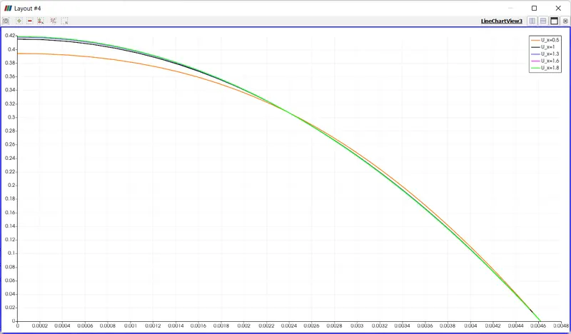
From the graph it is observed that at a distance of 1.6 m and 1.8 m, the velocity profiles overlap each other. This is a region of fully developed flow. The distance at 1.3 m also closely follows the line at 1.6 m and 1.8 m.
Also, it is observed that, the radius is not covered fully by y axis because we use 2 D simulation.
OBSERVATIONS
On increasing wedge angle, it is observed that the value of shear stress and pressure drop deviates from analytical solution. It is because, when the wedge angle is small, the thickness is very small, such that the centre of 2 wedges in pipe forms the radius of the pipe and it is close to 0.05.
But, when the wedge angle increases, we observed that the change in z direction is happening to one mesh only. So, it is not capturing the changes along the z direction because we selected 1 mesh in z direction. It is 2 D simulation.
In order to increase the accuracy, either increase the mesh along the z direction, but it will increase the number of cells. So, the best method is that decrease the wedge angle so as to get the better result. It will be close to analytical value
Difference between symmetry and wedge boundary conditions
A Wedge boundary is different from the symmetry boundary condition in the sense that the wedge boundary condition applies the Navier-Stokes (NS) equations in cylindrical coordinates whereas the latter applies the NS equations in cartesian coordinates. One big advantage of wedge boundary is that it allows for the rotational flow around the axis and this is possible only because the fluxes and normal components are not assumed as zero.
As I had done the symmetry boundary condition in week 11 challenge, I m not going again on symmetry boundary condition. Moreover, we are not studying the effect of rotational flow. So, no need to go again for symmetry boundary conditions because it will give the result same as wedge boundary conditions.